Analysis and Enhancement of Incremental-Quantity-Based Distance Protection With Grid-Forming Inverters
Pith reviewed 2026-05-10 15:45 UTC · model grok-4.3
The pith
A new trip criterion for incremental-quantity distance protection provides general settings that work reliably with grid-forming inverters.
A machine-rendered reading of the paper's core claim, the machinery that carries it, and where it could break.
Core claim
Grid-forming inverters, being nonlinear during faults due to current limiters, still permit the use of incremental-quantity superposition in protection analysis when modeled by fixed operating modes. The proposed trip criterion, derived from this model, enables dependable operation for internal faults and security for external faults with settings that do not require case-by-case adjustment for various GFM sources.
What carries the argument
The analytical model representing GFM inverter current limiter effects on relay incremental quantities, combined with the proposed trip criterion that adjusts the decision logic for improved interoperability.
If this is right
- Time-domain IQ-based distance protection shows superior dependability for close-in faults compared to quadrilateral distance protection when GFM inverters are present.
- The proposed settings can be secure for external faults in cases where quadrilateral protection would overreach.
- Settings become easy to generalize across different GFM inverter current limiters and fault scenarios.
- Interoperability issues with standard IQ protection are mitigated without losing the advantages of time-domain processing.
Where Pith is reading between the lines
- Such criteria could support protection schemes in highly inverter-dominated networks where phasor-based methods fail due to lack of inertia.
- Further validation in hardware-in-the-loop tests with real inverter controllers would strengthen confidence in the general settings.
- Integration with other time-domain protections like traveling-wave methods might offer hybrid solutions for full line coverage.
Load-bearing premise
The GFM inverter current limiter can be modeled with fixed operating modes whose transitions do not break the linearity assumption underlying the incremental-quantity superposition used by the relay.
What would settle it
A simulation or field test of an internal close-in fault with a GFM inverter using a different current limiter mode transition that causes the proposed criterion to fail to trip or to misoperate on an external fault.
Figures


read the original abstract
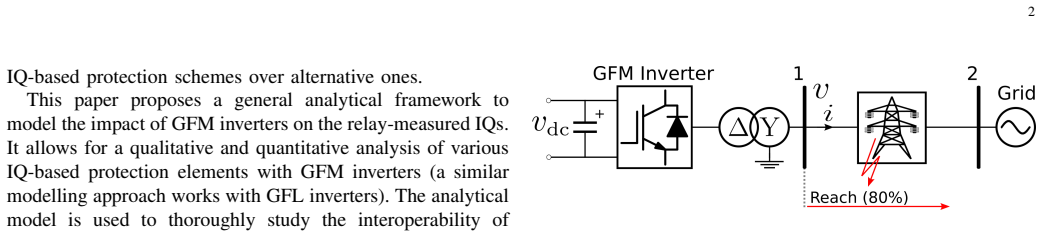
Grid-forming (GFM) inverters are expected in future inverter-dominated grids. In such grids, time-domain protection schemes, for example those based on instantaneous incremental quantities (IQs), are being advocated as potential solutions to the challenges faced by traditional phasor-based protection schemes, due to their ability to process nonlinear data. However, IQ-based protection uses the superposition principle; thus, linearity is still assumed in their application, while GFM inverters are nonlinear sources during faults. This paper proposes an analytical model to study the impact of GFM inverters on the relay-measured IQs. The model is validated with PSCAD/EMTDC simulations, and is used to investigate the interoperability of time-domain IQ-based distance protection with GFM inverters employing different current limiters. Results show that time-domain IQ-based distance protection demonstrates superior dependability for close-in faults compared to that of quadrilateral distance protection with GFM inverters, and it has the possibility to be secure for external faults when quadrilateral distance protection overreaches; however, tuning of its settings is hard to generalize for various sources and faults. Taking the observed interoperability issues into account, a trip criterion for dependable and secure time-domain IQ-based distance protection is proposed, which facilitates easy-to-tune and general settings for applications with GFM inverters.
Editorial analysis
A structured set of objections, weighed in public.
Referee Report
Summary. The paper develops an analytical model to characterize how grid-forming (GFM) inverters affect relay-measured incremental quantities (IQs) under different current-limiter implementations. The model is validated against PSCAD/EMTDC EMT simulations for multiple limiter types and fault locations. It shows that conventional IQ-based distance protection offers better dependability than quadrilateral distance protection for close-in faults with GFM inverters, yet its settings are difficult to generalize. The authors then propose a new trip criterion intended to provide easy-to-tune, general settings while preserving dependability for internal faults and security for external faults.
Significance. If the central modeling assumptions hold, the work supplies a first-principles analytical framework for a timely protection problem in inverter-dominated grids. The simulation-validated derivation of IQs and the concrete trip-criterion proposal constitute tangible contributions that could inform practical relay settings; the explicit comparison against quadrilateral protection and the emphasis on tuning generality are particularly useful.
major comments (3)
- [§3–4] §3–4: The analytical model represents the GFM inverter current limiter by a fixed set of operating modes and applies the superposition principle to obtain incremental quantities. The derivation therefore presupposes that mode transitions (voltage-to-current limiting, saturation entry/exit) do not occur on the timescale of the fault transient. No explicit analysis or additional simulation cases are provided to bound the validity of this assumption across limiter implementations or network topologies.
- [§5] §5: Validation is performed for several limiter types and fault locations, yet the reported cases do not include exhaustive checks for mid-fault mode transitions. Because the proposed trip criterion in §6 is derived directly from the IQ expressions obtained under the fixed-mode assumption, any violation of that assumption directly affects the claimed generality and dependability/security performance.
- [§6] §6: The assertion that the new trip criterion “facilitates easy-to-tune and general settings” rests on the analytical expressions; however, the manuscript provides no quantitative sensitivity study (e.g., variation of threshold margins with source strength, fault resistance, or limiter parameters) that would demonstrate reduced tuning effort relative to existing IQ or quadrilateral schemes.
minor comments (2)
- [Abstract, §1] The abstract and §1 should qualify statements about “superior dependability” and “secure for external faults” with reference to the specific simulation scenarios examined, to avoid implying unconditional generality.
- [§2] Notation for the incremental quantities (e.g., ΔV, ΔI) and the limiter-mode variables should be introduced once in §2 and used consistently thereafter; occasional redefinition in later sections reduces readability.
Simulated Author's Rebuttal
We thank the referee for the thorough review and valuable comments. We address each of the major comments below and have made revisions to the manuscript to strengthen the presentation and address the concerns raised.
read point-by-point responses
-
Referee: [§3–4] The analytical model represents the GFM inverter current limiter by a fixed set of operating modes and applies the superposition principle to obtain incremental quantities. The derivation therefore presupposes that mode transitions (voltage-to-current limiting, saturation entry/exit) do not occur on the timescale of the fault transient. No explicit analysis or additional simulation cases are provided to bound the validity of this assumption across limiter implementations or network topologies.
Authors: We agree that the model relies on the assumption of fixed limiter modes during the transient to enable the use of superposition. This assumption is justified for the fault inception and the short time window considered for incremental quantity calculation, as mode transitions typically require some time to develop. In the revised manuscript, we have expanded Section 3 to include a discussion of the validity conditions for this assumption, supported by references to typical GFM control response times. Additionally, we have added simulation cases in Section 5 across different network topologies to illustrate that mode transitions do not occur within the relevant timeframe for the studied limiter implementations. revision: yes
-
Referee: [§5] Validation is performed for several limiter types and fault locations, yet the reported cases do not include exhaustive checks for mid-fault mode transitions. Because the proposed trip criterion in §6 is derived directly from the IQ expressions obtained under the fixed-mode assumption, any violation of that assumption directly affects the claimed generality and dependability/security performance.
Authors: We acknowledge the importance of verifying the absence of mode transitions in the validation cases. The original simulations were designed to capture the steady-state post-fault behavior within the incremental quantity window, but we agree that explicit checks are beneficial. In the revised version, we have included plots and analysis in Section 5 showing the limiter operating mode over time for all validation cases, confirming no mid-fault transitions occur. This reinforces the applicability of the derived expressions and the proposed trip criterion. revision: yes
-
Referee: [§6] The assertion that the new trip criterion “facilitates easy-to-tune and general settings” rests on the analytical expressions; however, the manuscript provides no quantitative sensitivity study (e.g., variation of threshold margins with source strength, fault resistance, or limiter parameters) that would demonstrate reduced tuning effort relative to existing IQ or quadrilateral schemes.
Authors: The proposed trip criterion is designed such that the threshold setting is determined from the analytical model in a manner that is largely independent of specific system parameters, thereby facilitating general settings. To address the request for quantitative demonstration, we have added a sensitivity analysis in the revised Section 6. This analysis varies source strength, fault resistance, and limiter parameters, showing that the threshold margins remain robust and require less case-specific tuning compared to conventional schemes, as evidenced by the smaller variation in required settings. revision: yes
Circularity Check
No significant circularity: derivation from first-principles circuit equations with external simulation validation
full rationale
The paper constructs an analytical model of relay-measured incremental quantities under GFM inverters directly from circuit equations and the superposition principle, then validates it against independent PSCAD/EMTDC EMT simulations. The proposed trip criterion is subsequently derived from the model's predictions and observed interoperability issues. No fitted parameters are renamed as predictions, no self-citations are load-bearing for the central claims, and no ansatz or uniqueness result is imported from prior author work. The chain remains self-contained and externally falsifiable.
Axiom & Free-Parameter Ledger
free parameters (1)
- current-limiter threshold and mode-transition logic
axioms (1)
- domain assumption Superposition principle remains usable for incremental quantities once the source is represented by its equivalent circuit in each limiter mode.
Lean theorems connected to this paper
-
IndisputableMonolith/Foundation/AbsoluteFloorClosure.leanreality_from_one_distinction unclear?
unclearRelation between the paper passage and the cited Recognition theorem.
proposes an analytical model to study the impact of GFM inverters on the relay-measured IQs... pure-fault network... superposition principle
-
IndisputableMonolith/Cost/FunctionalEquation.leanwashburn_uniqueness_aczel unclear?
unclearRelation between the paper passage and the cited Recognition theorem.
ψop = |Δvsx − Δvmx|... running sums EΣx[n] ... trip threshold level
What do these tags mean?
- matches
- The paper's claim is directly supported by a theorem in the formal canon.
- supports
- The theorem supports part of the paper's argument, but the paper may add assumptions or extra steps.
- extends
- The paper goes beyond the formal theorem; the theorem is a base layer rather than the whole result.
- uses
- The paper appears to rely on the theorem as machinery.
- contradicts
- The paper's claim conflicts with a theorem or certificate in the canon.
- unclear
- Pith found a possible connection, but the passage is too broad, indirect, or ambiguous to say the theorem truly supports the claim.
Reference graph
Works this paper leans on
-
[1]
U. M ¨unz, S. Bhela, N. Xue, A. Banerjee, M. Reno, D. Kelly, E. Faran- tatos, A. Haddadi, D. Ramasubramanian, and A. Banaie, “Protection of 100% inverter-dominated power systems with grid-forming inverters and protection relays - gap analysis and expert interviews,” 04 2024
work page 2024
-
[2]
Impact of inverter based resources on system protection,
A. Haddadi, E. Farantatos, I. Kocar, and U. Karaagac, “Impact of inverter based resources on system protection,”Energies, vol. 14, no. 4,
-
[3]
Available: https://www.mdpi.com/1996-1073/14/4/1050
[Online]. Available: https://www.mdpi.com/1996-1073/14/4/1050
work page 1996
-
[4]
Line distance protection near unconventional energy sources,
B. Kasztenny, “Line distance protection near unconventional energy sources,” in16th International Conference on Developments in Power System Protection (DPSP 2022), vol. 2022, 2022, pp. 224–229
work page 2022
-
[5]
Transmission line protection challenges in- fluenced by inverter-based resources: A review,
J. C. Quispe and E. Ordu ˜na, “Transmission line protection challenges in- fluenced by inverter-based resources: A review,”Protection and Control of Modern Power Systems, vol. 7, no. 3, pp. 1–17, 2022
work page 2022
-
[6]
Transmission line protection for systems with inverter-based resources – part i: Problems,
R. Chowdhury and N. Fischer, “Transmission line protection for systems with inverter-based resources – part i: Problems,”IEEE Transactions on Power Delivery, vol. 36, no. 4, pp. 2416–2425, 2021
work page 2021
-
[7]
“High penetration of power electronic interfaced power sources and the potential contribution of grid forming converters,” European Network of Transmission System Operators for Electricity, Tech. Rep., 2020
work page 2020
-
[8]
Protection challenges and solutions for ac systems with renewable energy sources: A review,
Z. Yang, H. Wang, W. Liao, C. L. Bak, and Z. Chen, “Protection challenges and solutions for ac systems with renewable energy sources: A review,”Protection and Control of Modern Power Systems, vol. 10, no. 1, pp. 18–39, 2025
work page 2025
-
[9]
Impacts of grid- forming inverters on distance protection,
H. Johansson, Q. Xing, N. Taylor, and X. Wang, “Impacts of grid- forming inverters on distance protection,”IET Generation, Transmission & Distribution, vol. 19, no. 1, p. e13354, 2025. [Online]. Available: https://ietresearch.onlinelibrary.wiley.com/doi/abs/10.1049/gtd2.13354
-
[10]
A time-domain protection approach for ac transmission systems with grid-forming resources,
C. L. Peralta and H. N. V . Pico, “A time-domain protection approach for ac transmission systems with grid-forming resources,”IEEE Trans- actions on Instrumentation and Measurement, vol. 73, pp. 1–18, 2024
work page 2024
-
[11]
C. Chao, X. Zheng, Y . Weng, Z. Liu, H. Ye, H. Liu, H. Zhang, Y . Liu, Y . Wang, and N. Tai, “Collaborative solution of distance protection and dual current control for outgoing lines of inverter-based resources during line-to-line faults,”IEEE Transactions on Smart Grid, vol. 15, no. 4, pp. 3782–3794, 2024
work page 2024
-
[12]
N. George, O. D. Naidu, and A. K. Pradhan, “Distance protection for lines connecting converter interfaced renewable power plants: Adaptive to grid-end structural changes,”IEEE Transactions on Power Delivery, vol. 38, no. 3, pp. 2011–2021, 2023
work page 2011
-
[13]
O. D. Naidu, N. George, S. Zubic, and M. Krakowski, “Time-domain- based distance protection for transmission networks: Secure and reliable solution for complex networks,”IEEE Access, vol. 11, pp. 104 656– 104 675, 2023
work page 2023
-
[14]
N. George, O. D. Naidu, and A. Kumar Pradhan, “Source-agnostic single-ended protection and fault location for double-circuit lines con- nected to power electronics-based sources,”IEEE Access, vol. 13, pp. 132 038–132 051, 2025
work page 2025
-
[15]
On the distance protection of power grids dominated by grid-forming invert- ers,
N. Baeckeland, D. Venkatramanan, S. Dhople, and M. Kleemann, “On the distance protection of power grids dominated by grid-forming invert- ers,” in2022 IEEE PES Innovative Smart Grid Technologies Conference Europe (ISGT-Europe), 2022, pp. 1–6
work page 2022
-
[16]
Evaluation of grid-forming converter’s impact on distance protection performance,
D. Liu, Q. Hong, M. A. U. Khan, A. Dy ´sko, A. E. Alvarez, and C. Booth, “Evaluation of grid-forming converter’s impact on distance protection performance,” in16th International Conference on Developments in Power System Protection (DPSP 2022), vol. 2022, 2022, pp. 285–290
work page 2022
-
[17]
J. Vermunicht, W. Leterme, and D. Van Hertem, “Analysing the performance of incremental quantity based directional time-domain protection near HV AC cables and VSC HVDC converters,”Electric Power Systems Research, vol. 223, p. 109599, 2023. [Online]. Available: https://www.sciencedirect.com/science/article/pii/S0378779623004881
work page 2023
-
[18]
Differential protection for lines connected to inverter-based resources: Problems and solution,
N. George, O. Naidu, and A. K. Pradhan, “Differential protection for lines connected to inverter-based resources: Problems and solution,” in 2022 22nd National Power Systems Conference (NPSC), 2022, pp. 419– 424
work page 2022
-
[19]
Distance protection for lines connected with type iii wind farms: Problems and solution,
O. D. Naidu, N. George, and V . Pradhan, “Distance protection for lines connected with type iii wind farms: Problems and solution,” in2023 IEEE PES 15th Asia-Pacific Power and Energy Engineering Conference (APPEEC), 2023, pp. 1–6
work page 2023
-
[20]
Differential equa- tion algorithms for distance relays in the presence of inverter-based resources,
H. Johansson, Q. Xing, N. Taylor, and X. Wang, “Differential equa- tion algorithms for distance relays in the presence of inverter-based resources,” in18th International Conference on Developments in Power System Protection (DPSP APAC 2025), vol. 2025, 2025, pp. 211–221
work page 2025
-
[21]
Performance of time-domain line protection elements on real-world faults,
E. O. Schweitzer, B. Kasztenny, and M. V . Mynam, “Performance of time-domain line protection elements on real-world faults,” in2016 69th Annual Conference for Protective Relay Engineers (CPRE), 2016, pp. 1–17
work page 2016
-
[22]
Distance protection: Why have we started with a circle, does it matter, and what else is out there?
E. O. Schweitzer and B. Kasztenny, “Distance protection: Why have we started with a circle, does it matter, and what else is out there?” in2018 71st Annual Conference for Protective Relay Engineers (CPRE), 2018, pp. 1–19
work page 2018
-
[23]
M. T. Hoq, J. Wang, and N. Taylor, “An incremental quantity based distance protection with capacitor voltage estimation for series com- pensated transmission lines,”IEEE Access, vol. 9, pp. 164 493–164 502, 2021
work page 2021
-
[24]
An incremental quantities distance protection using park’s transformation,
Y . Chen, M. Wen, Z. Wang, X. Yin, and D. Chen, “An incremental quantities distance protection using park’s transformation,”IEEE Trans- actions on Power Delivery, vol. 37, no. 4, pp. 3200–3212, 2022
work page 2022
-
[25]
Incremental quantities protection schemes with grid-forming inverters,
H. Johansson, Q. Xing, N. Taylor, and X. Wang, “Incremental quantities protection schemes with grid-forming inverters,” in19th IET Conference on Developments in Power System Protection (DPSP Europe 2025), vol. 2025, 2025, pp. 277–289
work page 2025
-
[26]
Impact of distributed inverter-based resources on incremental quantities-based protection,
H. S. Samkari and B. K. Johnson, “Impact of distributed inverter-based resources on incremental quantities-based protection,” in2021 IEEE Power & Energy Society General Meeting (PESGM), 2021, pp. 1–5
work page 2021
-
[27]
New phase selection solution for distance protection with different system conditions,
J. Wang, Y . Li, M. Tajdinian, and M. T. Hoq, “New phase selection solution for distance protection with different system conditions,” in19th IET Conference on Developments in Power System Protection (DPSP Europe 2025), vol. 2025, 2025, pp. 217–221
work page 2025
-
[28]
A tutorial on calculating source impedance ratios for determining line length,
M. J. Thompson and A. Somani, “A tutorial on calculating source impedance ratios for determining line length,” in2015 68th Annual Conference for Protective Relay Engineers, 2015, pp. 833–841
work page 2015
-
[29]
A review of current- limiting control of grid-forming inverters under symmetrical distur- bances,
B. Fan, T. Liu, F. Zhao, H. Wu, and X. Wang, “A review of current- limiting control of grid-forming inverters under symmetrical distur- bances,”IEEE Open Journal of Power Electronics, vol. 3, pp. 955–969, 2022
work page 2022
-
[30]
Overcurrent limiting in grid-forming inverters: A comprehensive review and discussion,
N. Baeckeland, D. Chatterjee, M. Lu, B. Johnson, and G.-S. Seo, “Overcurrent limiting in grid-forming inverters: A comprehensive review and discussion,”IEEE Transactions on Power Electronics, vol. 39, no. 11, pp. 14 493–14 517, 2024
work page 2024
-
[31]
B. Fan and X. Wang, “Equivalent circuit model of grid-forming convert- ers with circular current limiter for transient stability analysis,”IEEE Transactions on Power Systems, vol. 37, no. 4, pp. 3141–3144, 2022
work page 2022
discussion (0)
Sign in with ORCID, Apple, or X to comment. Anyone can read and Pith papers without signing in.