REVIEW 5 major objections 3 minor 36 references
A 3-Step Optimization Framework with Hybrid Models for a Humanoid Robot's Jump Motion
T0 review · 5 major / 3 minor · reviewed 2026-08-10 · deepseek-v4-flash
Pith's one-line read The paper claims that a 3-step trajectory optimization framework, using an SRMP model, joint-space QP mapping, and whole-body optimization, generates executable forward jumps of 1.0 m distance and 0.5 m height on a humanoid robot, with…
desk verdict A real robot doing 1m forward jumps is the bottom line; the paper is a credible engineering contribution with some under-specified validation. read the letter →
The pith
A machine-rendered reading of the paper's core claim, the machinery that carries it, and where it could break.
The reading
What carries the argument
The central object is the SRMP (static reaction mass pendulum) model, a 2D pendulum whose center of mass is split into a barbell of two masses separated by a controllable radius $\varphi$, giving total rotational inertia $\rho = 2 m_p \varphi^2$. This scalar encodes the robot's body inertia, letting the optimizer shape inertia during flight while total angular momentum is conserved. The center-of-pressure constraint (Eq. 22) couples linear and angular momentum to the support region, and the flight-phase optimization treats the spatial inertia $\rho^R_{\text{total}}$ as the control variable to adjust the landing posture.
What would settle it
Use external motion capture to measure the robot's actual takeoff velocity and flight-phase pitch rotation during a forward jump: if the horizontal center-of-mass velocity at takeoff differs from the planned value by more than the landing controller can absorb, or if the robot's roll or yaw grows beyond a small threshold, the planar symmetry assumption behind the whole-body stage is violated and the claimed 1.0 m jump is not reproducible.
Extended reading notes
Core claim
The central claim is that the coupling between body posture and centroidal angular momentum during launch, and the inertia shaping that controls rotation during flight, can be optimized together by a split-level approach. A static reaction mass pendulum (SRMP)—a pendulum whose endpoint mass is a barbell of adjustable radius—captures both the momentum and the rotational inertia of the robot, and its optimization produces reference trajectories for momentum, inertia, and center of pressure. The paper asserts that these references, after a joint-space mapping step and a final whole-body optimization on a planar 5-link model, yield a trajectory that the real robot can execute open-loop through launch and flight, landing with the feet placed for a stable touchdown.
Load-bearing premise
The final optimization runs on a planar 5-link model that merges the two legs into one, so the whole plan assumes the robot's left and right legs move identically and that roll and yaw dynamics are negligible; if the real robot breaks that symmetry, the planned center-of-pressure and landing postures are not dynamically consistent.
Editorial extensions
If this is right
- Total optimization time under 10 seconds makes the framework feasible for online re-planning when jump targets change.
- Inertia shaping during flight gives the robot control over landing orientation without breaking angular momentum conservation, so landing foot placement can be planned.
- The center-of-pressure constraint links linear and angular momentum to the support region, so the optimized launch trajectory is executable without foot tipping.
- The same split-level approach can be applied to other sagittal-plane jumps, such as backflips, by changing the target rotation.
Reading between the lines
- The planar symmetry reduction suggests an obvious stress test: deliberately perturb the robot's initial posture in roll and yaw and see if the open-loop trajectory still lands stably; the paper does not report such a test.
- The 10-second runtime depends on the QP mapping providing a good guess; this staged warm-start strategy could be reused in other whole-body optimal control problems, such as running takeoffs or stair hopping.
- The paper's own admission that model error can be pre-compensated by biasing optimization goals hints that a sensitivity analysis—how much target bias per unit of model error—would turn the framework into a robust tuning tool.
- If the inertia-shaping flight phase is the key new element, one could test it in isolation by executing only the flight-phase trajectory during a no-jump, in-place rotation maneuver.
Editorial analysis
A structured set of objections, weighed in public.
Referee Report
Summary. The paper proposes a three-stage offline trajectory optimization framework for generating forward jump motions on an adult-sized humanoid robot. Stage 1 uses a 2D SRMP model to optimize centroidal momentum, inertia, and CoP trajectories for the launching and flight phases; Stage 2 maps these trajectories into joint space via QP solvers on a 20-DOF full-body model; Stage 3 performs a whole-body optimization on a planar 5-link model whose leg mass and inertia are aggregated from the two legs, with the resulting trajectory mirrored to both legs. The optimized trajectory is executed open-loop in position mode during launching and flight, with a landing controller inherited from prior work. The central claims are that the three-stage framework generates agile forward jumps of about 1.0 m distance and 0.5 m height, that the whole optimization takes less than 10 seconds, and that inertia shaping during flight achieves favorable landing posture.
Significance. If fully validated, the framework would be a practical and fast trajectory-optimization pipeline for humanoid jumping, with a sensible hierarchical decomposition: SRMP-based momentum/inertia generation, QP-based joint-space mapping, and whole-body refinement. The physical robot experiments in Sec. VI-C show real forward jumps, which is nontrivial evidence that the optimized trajectories are executable, and the paper usefully identifies inertia shaping during flight as a key ingredient for landing posture. However, the validation is incomplete: there are no error bars, only selected trials are shown, the flight-phase CoM/CAM are not directly measured, bilateral ground-reaction data are absent, and admitted discrepancies between reference and actual performance are rationalized rather than quantified. The central methodological bridge from the planar symmetric whole-body model to the physical two-legged robot is therefore not yet demonstrated.
major comments (5)
- [Sec. II-C and Sec. V] The whole-body optimization uses a planar 5-link single-legged model whose leg mass and inertia are the sum of the two legs, and the resulting trajectory is mirrored to both legs. This assumes exact left-right symmetry and identical ground reactions during launch and landing. The paper never reports bilateral force/torque sensor data or CoP tracks from the experiments, so the dynamic consistency of the planned CoP constraint (Eq. 22) and the CAM trajectory with the real two-legged motion is not established. Please provide per-foot ground-reaction force and CoP measurements for the reported trials, or explicitly state the symmetry assumption and justify it with data.
- [Sec. VI-C, Fig. 14] The paper states that the robot does not reach the specified CoM height and that the actual CAM deviates from the reference, then suggests these discrepancies 'might be attributed to measurement errors' without supporting evidence. Because the flight-phase CoM and CAM are not measured (no external motion capture or state estimator), the claimed 1.0 m distance and 0.5 m height cannot be directly verified from the presented data. Please report multiple trials with error bars, measured takeoff velocity, measured flight-phase trajectories, or clearly limit the claim to selected successful trials.
- [Sec. VI-B] The simulation section says that model mismatch can be handled by 'adding bias to the optimization's goal,' but no definition, numerical value, or tuning procedure for this bias is given. This is a load-bearing detail for reproducibility, since the bias appears to be the mechanism by which the framework compensates for dynamic-model differences. Specify where the bias enters the optimization (objective or constraint), how it was selected, and whether it was tuned on the experimental trials.
- [Sec. I and Sec. VI] The paper claims that the whole optimization process takes less than 10 seconds, but no timing measurements, solver specifications, problem sizes, or hardware details are reported anywhere in the results. Since this is one of the stated contributions and is essential for the claimed online deployability, please provide quantitative timing data for each of the three optimization stages.
- [Sec. VI-B, Fig. 12] The simulation validation shows visible differences between reference and actual CoM position/velocity and CAM curves, attributed to dynamic model differences, but no quantitative error metric or acceptance threshold is given. Given that the simulation also uses modified dynamic parameters and open-loop execution, please quantify the tracking errors and show that the achieved jump distance and height match the targets within a defined tolerance.
minor comments (3)
- [Throughout] There are several typos and grammatical errors, including 'researches' and 'constracted' in Sec. I, 'the relationship the relationship' in Sec. IV-A, and 'cased' in Sec. VI-B. The paper would benefit from a careful language edit.
- [Fig. 12] The subplot captions in Fig. 12 are not self-contained; please specify in the caption which physical quantities are plotted and clarify the meaning of 'Ref' and 'Act'.
- [Sec. II-A and Sec. III-A] The symbol φ is used for the barbell radius in the SRMP configuration (Eq. 1) and also appears in derived quantities such as Eq. 4; the notation should be checked for consistency to avoid confusion between radius and other angular variables.
Circularity Check
No significant circularity: the 1.0 m / 0.5 m jump targets are optimization inputs, not fitted outputs, and the self-cited equations and controller from [2] are reused as standard dynamics and landing support rather than as the source of the claimed forward-jump derivation.
full rationale
The derivation chain starts from externally selected jump height h and distance l. Section III-A3 imposes these as hard constraints: Eq. (17) requires 2*p_end_c0x + v_end_c0x*t_f = l, and Eq. (18) requires v_end_c0z = sqrt(2*g*h). The validation targets therefore enter as inputs, not as quantities recovered from the experimental outcome. Each subsequent stage propagates these targets through independent dynamics models (SRMP, full-DOF QP, and 5-link whole-body optimization), and the paper reports open-loop execution with visible tracking errors rather than claiming that the model reproduced measured data. The reused equations from the authors' prior vertical-jump paper [2]—centroidal dynamics, tiptoe constraints, and the landing controller—are standard contact/centroidal relations and a previously demonstrated landing controller; they are not used to force the forward-jump distance or height, and the paper invokes no uniqueness theorem to forbid alternatives. The vague 'bias to the optimization's goal' in Sec. VI-B is an admitted compensation knob, but no value or fitted parameter is specified, so it cannot be identified as a fitted input renamed as a prediction on the quoted evidence. The planar single-legged symmetry reduction in Sec. II-C is a correctness and robustness risk rather than a circularity: it is an approximation stated before the optimization and is falsifiable against the reported simulation and experiment errors.
Assumptions & free parameters
free parameters (5)
- Cost weight matrices =
not reported
- State and control bounds =
not reported
- Inertia and momentum limits =
rho_min_sr, rho_max_sr, Lmin, Lmax not reported
- CoP support limits =
X_min_CoP, X_max_CoP not reported
- Model-compensation bias =
not reported
assumptions (6)
- domain assumption The jump can be split into launching and flight phases with the landing angle symmetric to the launching angle (Sec. III, Eq. 17 and Eq. 27).
- domain assumption The two legs move identically, so the 5-link single-legged model with aggregated leg mass and inertia represents the full robot (Sec. II-C).
- domain assumption During flight, angular momentum and horizontal linear momentum are exactly conserved, so inertia shaping is the only control of posture (Sec. III-B, Eq. 26).
- domain assumption The fixed-base SRMP model with unlimited support force and torque, plus CoP bounds, is a valid surrogate for the contact dynamics of the launching phase (Sec. III-A5, Eq. 22).
- standard math Lagrangian equations of motion for the three models (Eqs. 2, 6, 8) describe the robot's dynamics accurately.
- ad hoc to paper The manually set cost weights and state and control bounds can be chosen so the optimum is feasible on the physical robot (Secs. III to V).
Cite this review
Pith. "Pith review of A 3-Step Optimization Framework with Hybrid Models for a Humanoid Robot's Jump Motion." pith.science (2026). https://pith.science/paper/SCLA2D2K
@misc{pith2026250112594,
  author       = {Pith},
  title        = {Pith review of: A 3-Step Optimization Framework with Hybrid Models for a Humanoid Robot's Jump Motion},
  year         = {2026},
  howpublished = {\url{https://pith.science/paper/SCLA2D2K}},
  note         = {Machine review of arXiv:2501.12594}
}
read the original abstract
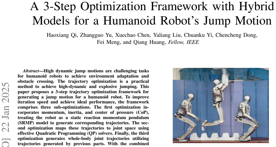
High dynamic jump motions are challenging tasks for humanoid robots to achieve environment adaptation and obstacle crossing. The trajectory optimization is a practical method to achieve high-dynamic and explosive jumping. This paper proposes a 3-step trajectory optimization framework for generating a jump motion for a humanoid robot. To improve iteration speed and achieve ideal performance, the framework comprises three sub-optimizations. The first optimization incorporates momentum, inertia, and center of pressure (CoP), treating the robot as a static reaction momentum pendulum (SRMP) model to generate corresponding trajectories. The second optimization maps these trajectories to joint space using effective Quadratic Programming (QP) solvers. Finally, the third optimization generates whole-body joint trajectories utilizing trajectories generated by previous parts. With the combined consideration of momentum and inertia, the robot achieves agile forward jump motions. A simulation and experiments (Fig. \ref{Fig First page fig}) of forward jump with a distance of 1.0 m and 0.5 m height are presented in this paper, validating the applicability of the proposed framework.
Figures


Figures from the paper (11 more)


Reference graph
Works this paper leans on
-
[1]
B. Dynamics, “What’s new, atlas?” https://youtu.be/fRj34o4hN4I, 2017, accessed on Jan 12, 2020
work page 2017
-
[2]
Vertical jump of a humanoid robot with cop-guided angular momentum control and impact absorption,
H. Qi, X. Chen, Z. Yu, G. Huang, Y . Liu, L. Meng, and Q. Huang, “Vertical jump of a humanoid robot with cop-guided angular momentum control and impact absorption,” IEEE Transactions on Robotics , 2023
work page 2023
-
[3]
A vertical jump optimization strategy for one-legged robot with variable reduction ratio joint,
H. Qi, X. Chen, Z. Yu, H. Gao, L. Meng, K. Hashimoto, W. Liao, and Q. Huang, “A vertical jump optimization strategy for one-legged robot with variable reduction ratio joint,” in 2020 International Conference on Humanoid Robot (Humanoids) . IEEE, 2020, pp. 3712–3718
work page 2020
-
[4]
Motion control in the support phase for a one-legged hopping robot,
K. Ohnishi and E. Ohashi, “Motion control in the support phase for a one-legged hopping robot,” in The 8th IEEE International Workshop on Advanced Motion Control, 2004. AMC’04. IEEE, 2004, pp. 259–262
work page 2004
-
[5]
Control strategy for planar vertical jump,
V . Nunez, S. Drakunov, N. Nadjar-Gauthier, and J. Cadiou, “Control strategy for planar vertical jump,” in ICAR’05. Proceedings., 12th International Conference on Advanced Robotics, 2005. IEEE, 2005, pp. 849–855
work page 2005
-
[6]
Biped robot vertical jumping with control constraints,
A. Sripada, J. Vistapalli, and R. P. Kumar, “Biped robot vertical jumping with control constraints,” in 2018 IEEE International Conference on Robotics and Biomimetics (ROBIO) . IEEE, 2018, pp. 1683–1687
work page 2018
-
[7]
Kinematic analysis of biped robot forward jump for safe locomotion,
V . Janardhan and R. Kumar, “Kinematic analysis of biped robot forward jump for safe locomotion,” in Proceedings of the 1st International and 16th National Conference on Machines and Mechanisms , 2013, pp. 1078–1082
work page 2013
-
[8]
Development of high-span running long jumps for humanoids,
P. M. Wensing and D. E. Orin, “Development of high-span running long jumps for humanoids,” in 2014 IEEE International Conference on Robotics and Automation (ICRA) . IEEE, 2014, pp. 222–227
work page 2014
Show all 36 references
-
[9]
Torque and velocity controllers to perform jumps with a humanoid robot: theory and implementation on the icub robot,
F. Bergonti, L. Fiorio, and D. Pucci, “Torque and velocity controllers to perform jumps with a humanoid robot: theory and implementation on the icub robot,” in 2019 International Conference on Robotics and Automation (ICRA). IEEE, 2019, pp. 3712–3718
2019
-
[10]
Bipedal hopping: Reduced-order model embedding via optimization-based control,
X. Xiong and A. D. Ames, “Bipedal hopping: Reduced-order model embedding via optimization-based control,” in 2018 IEEE/RSJ Interna- tional Conference on Intelligent Robots and Systems (IROS) . IEEE, 2018, pp. 3821–3828
2018
-
[11]
Improved computation of the humanoid centroidal dynamics and application for whole-body control,
P. M. Wensing and D. E. Orin, “Improved computation of the humanoid centroidal dynamics and application for whole-body control,” Interna- tional Journal of Humanoid Robotics, vol. 13, no. 01, p. 1550039, 2016
2016
-
[12]
Sequential motion planning for bipedal somersault via flywheel slip and momentum transmission with task space control,
X. Xiong and A. D. Ames, “Sequential motion planning for bipedal somersault via flywheel slip and momentum transmission with task space control,” in 2020 IEEE/RSJ International Conference on Intelligent Robots and Systems (IROS) . IEEE, 2020, pp. 3510–3517
2020
-
[13]
Optimized jumping on the mit cheetah 3 robot,
Q. Nguyen, M. J. Powell, B. Katz, J. Di Carlo, and S. Kim, “Optimized jumping on the mit cheetah 3 robot,” in 2019 International Conference on Robotics and Automation (ICRA) . IEEE, 2019, pp. 7448–7454
2019
-
[14]
The mit humanoid robot: Design, motion planning, and control for acrobatic behaviors,
M. Chignoli, D. Kim, E. Stanger-Jones, and S. Kim, “The mit humanoid robot: Design, motion planning, and control for acrobatic behaviors,” in 2020 IEEE-RAS 20th International Conference on Humanoid Robots (Humanoids). IEEE, 2021, pp. 1–8
2020
-
[15]
Whole-body motion planning with centroidal dynamics and full kinematics,
H. Dai, A. Valenzuela, and R. Tedrake, “Whole-body motion planning with centroidal dynamics and full kinematics,” in 2014 IEEE-RAS International Conference on Humanoid Robots . IEEE, 2014, pp. 295– 302
2014
-
[16]
Unified motion planner for walking, running, and jumping using the three-dimensional divergent component of motion,
G. Mesesan, R. Schuller, J. Englsberger, C. Ott, and A. Albu-Sch ¨affer, “Unified motion planner for walking, running, and jumping using the three-dimensional divergent component of motion,” IEEE Transactions on Robotics, 2023
2023
-
[17]
Online adaptive motion generation for humanoid locomotion on non-flat terrain via template behavior extension,
X. Meng, Z. Yu, X. Chen, Z. Huang, F. Meng, and Q. Huang, “Online adaptive motion generation for humanoid locomotion on non-flat terrain via template behavior extension,” IEEE Transactions on Automation Science and Engineering , 2023
2023
-
[18]
Cajun: Continuous adaptive jumping using a learned centroidal controller,
Y . Yang, G. Shi, X. Meng, W. Yu, T. Zhang, J. Tan, and B. Boots, “Cajun: Continuous adaptive jumping using a learned centroidal controller,” arXiv preprint arXiv:2306.09557 , 2023
2023 arXiv
-
[19]
Robust and versatile bipedal jumping control through multi-task rein- forcement learning,
Z. Li, X. B. Peng, P. Abbeel, S. Levine, G. Berseth, and K. Sreenath, “Robust and versatile bipedal jumping control through multi-task rein- forcement learning,” arXiv preprint arXiv:2302.09450 , 2023
2023 arXiv
-
[20]
Safe and adaptive 3-d locomotion via constrained task-space imitation learning,
J. Ding, T. L. Lam, L. Ge, J. Pang, and Y . Huang, “Safe and adaptive 3-d locomotion via constrained task-space imitation learning,” IEEE/ASME Transactions on Mechatronics, 2023
2023
-
[21]
Efficient dynamic computer simulation of robotic mechanisms,
M. W. Walker and D. E. Orin, “Efficient dynamic computer simulation of robotic mechanisms,” 1982
1982
-
[22]
Generalized direction changing fall control of humanoid robots among multiple objects,
U. Nagarajan and A. Goswami, “Generalized direction changing fall control of humanoid robots among multiple objects,” in 2010 IEEE International Conference on Robotics and Automation . IEEE, 2010, pp. 3316–3322
2010
-
[23]
Safe fall: Humanoid robot fall direction change through intelligent stepping and inertia shaping,
S.-k. Yun, A. Goswami, and Y . Sakagami, “Safe fall: Humanoid robot fall direction change through intelligent stepping and inertia shaping,” in 2009 IEEE international conference on robotics and automation. IEEE, 2009, pp. 781–787
2009
-
[24]
Online balanced motion generation for humanoid robots,
G. Ficht and S. Behnke, “Online balanced motion generation for humanoid robots,” in 2018 IEEE-RAS 18th International Conference on Humanoid Robots (Humanoids) . IEEE, 2018, pp. 1–9
2018
-
[25]
Fast whole-body motion control of humanoid robots with inertia constraints,
——, “Fast whole-body motion control of humanoid robots with inertia constraints,” in 2020 IEEE International Conference on Robotics and Automation (ICRA). IEEE, 2020, pp. 6597–6603
2020
-
[26]
The momentum equilibrium principle: Foot contact stabilization with relative angular momentum/velocity,
D. N. Nenchev, “The momentum equilibrium principle: Foot contact stabilization with relative angular momentum/velocity,” in 2018 IEEE- RAS 18th International Conference on Humanoid Robots (Humanoids) . IEEE, 2018, pp. 17–24
2018
-
[27]
The reaction mass biped: Geometric mechanics and control,
A. Siravuru, S. P. Viswanathan, K. Sreenath, and A. K. Sanyal, “The reaction mass biped: Geometric mechanics and control,” Journal of Intelligent & Robotic Systems , vol. 89, pp. 155–173, 2018
2018
-
[28]
Mpc-based locomotion control of bipedal robots with line-feet contact using centroidal dynamics,
G. Garc ´ıa, R. Griffin, and J. Pratt, “Mpc-based locomotion control of bipedal robots with line-feet contact using centroidal dynamics,” in 2020 IEEE-RAS 20th International Conference on Humanoid Robots (Humanoids). IEEE, 2021, pp. 276–282
2020
-
[29]
Control of rotational dynamics for ground and aerial behavior,
V . Zordan, D. Brown, A. Macchietto, and K. Yin, “Control of rotational dynamics for ground and aerial behavior,” IEEE transactions on visual- ization and computer graphics , vol. 20, no. 10, pp. 1356–1366, 2014
2014
-
[30]
Momentum-mapped inverted pendulum models for controlling dynamic human motions,
T. Kwon and J. K. Hodgins, “Momentum-mapped inverted pendulum models for controlling dynamic human motions,” ACM Transactions on Graphics (TOG), vol. 36, no. 1, pp. 1–14, 2017
2017
-
[31]
Momentum- aware trajectory optimization and control for agile quadrupedal locomo- tion,
Z. Zhou, B. Wingo, N. Boyd, S. Hutchinson, and Y . Zhao, “Momentum- aware trajectory optimization and control for agile quadrupedal locomo- tion,” arXiv preprint arXiv:2203.01548 , 2022
2022 arXiv
-
[32]
Reaction mass pendulum (RMP): An explicit model for centroidal angular momentum of humanoid robots,
S.-H. Lee and A. Goswami, “Reaction mass pendulum (RMP): An explicit model for centroidal angular momentum of humanoid robots,” in Proceedings 2007 IEEE international conference on robotics and automation. IEEE, 2007, pp. 4667–4672
2007
-
[33]
Dynamics and balance control of the reaction mass pendulum: a three-dimensional multibody pendulum with variable body inertia,
A. K. Sanyal and A. Goswami, “Dynamics and balance control of the reaction mass pendulum: a three-dimensional multibody pendulum with variable body inertia,” Journal of Dynamic Systems, Measurement, and Control, vol. 136, no. 2, p. 021002, 2014
2014
-
[34]
Motion having a flight phase: Experiments in- volving a one-legged robot,
R. Tajima and K. Suga, “Motion having a flight phase: Experiments in- volving a one-legged robot,” in2006 IEEE/RSJ International Conference on Intelligent Robots and Systems . IEEE, 2006, pp. 1726–1731
2006
-
[35]
Centroidal dynamics of a humanoid robot,
D. E. Orin, A. Goswami, and S.-H. Lee, “Centroidal dynamics of a humanoid robot,” Autonomous robots, vol. 35, pp. 161–176, 2013
2013
-
[36]
Coppeliasim (formerly v- rep): a versatile and scalable robot simulation framework,
E. Rohmer, S. P. N. Singh, and M. Freese, “Coppeliasim (formerly v- rep): a versatile and scalable robot simulation framework,” in Proc. of The International Conference on Intelligent Robots and Systems (IROS) , 2013, www.coppeliarobotics.com. Haoxiang Qi received B.S. degree ...
2013
Reviewed August 10, 2026 · model on record in the stance chip above.
Discussion (0). Continue with ORCID to comment.