REVIEW 4 major objections 5 minor 15 references
Direction Finding for Software Defined Radios with Switched Uniform Circular Arrays
T0 review · 4 major / 5 minor · reviewed 2026-08-08 · deepseek-v4-flash
Pith's one-line read Switched circular array on one receiver hits 4.7-degree accuracy.
desk verdict Solid chamber validation of a cheap switched-UCA DoA system, but the abstract overstates the real-world evidence and the signal-processing equations need cleanup. read the letter →
The pith
A machine-rendered reading of the paper's core claim, the machinery that carries it, and where it could break.
The reading
What carries the argument
The load-bearing mechanism is pseudo-coherent recovery: with the reference signal $X_r^m(t)$, each switched element is combined as $X_s^m(t)=X_a^m(t)\odot (X_r^m(t))^*$ and averaged over time, cancelling the random sampling phase. The calibration matrix $\mathbf{B}$, solved as a least-squares fit from measured steering vectors to ideal virtual-ULA steering vectors, compensates for mutual coupling and array imperfections. The virtual-ULA transform $\tilde{\mathbf{R}}_X = \mathbf{J}\mathbf{F}\mathbf{R}_X$ with Bessel-function weighting enables forward-backward spatial smoothing, and the MUSIC spectrum is then evaluated on the smoothed covariance matrix.
What would settle it
A controlled open-field test with a single known reflector would settle it: aim the calibrated array at a 2.4 GHz transmitter at a known angle, place one metal plate at a measured position, and check whether the MUSIC peak stays within a few degrees of the true angle; losing the peak to the reflector under a single reflection would contradict the light-multipath claim.
Extended reading notes
Core claim
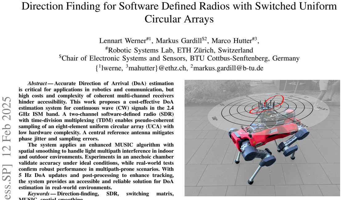
The central discovery is that pseudo-coherent sampling can stand in for true coherent sampling on a circular array: multiplying each sequentially switched antenna signal by the conjugate of a fixed central reference signal removes the random switching phase, leaving a phase that depends only on the direction of arrival. After a spatial-DFT transform into a virtual uniform linear array and a least-squares calibration matrix that absorbs mutual coupling and imperfections, the covariance matrix is spatially smoothed and fed to MUSIC. The pipeline achieves a mean absolute angle error of 4.7 degrees and a mean sidelobe level of 12.3 dB in an anechoic chamber, and it tracks a handheld 2.4 GHz transmitter in indoor and outdoor settings, with the sidelobe level dropping to about 6 dB under stronger multipath.
Load-bearing premise
The real-world results rest on the assumption that the compensation measured once in a lab still works after the antenna is moved onto a robot and used in multipath-rich rooms and streets.
Editorial extensions
If this is right
- The system reproduces coherent-array direction finding with only two receiver channels, making DoA hardware accessible to robotics and communication tasks.
- A single anechoic-chamber calibration taken at 20-degree increments is sufficient to compensate the array for later robot-mounted use.
- Forward-backward spatial smoothing lets the MUSIC estimator handle light indoor and outdoor multipath while keeping a 4.7-degree mean absolute angle error in the chamber.
- At a 5 Hz update rate with low-pass filtering of the angle estimates, the system tracks a moving handheld transmitter despite occasional multipath-induced jumps.
- Strong multipath, such as several people entering the scene, drops the sidelobe level toward 6 dB and can break lock, defining the reliable operating envelope.
Reading between the lines
- The paper leaves implicit that the anechoic-chamber calibration is the part most likely to break in deployment: any change in cable routing, connector wear, or nearby metal on the robot changes mutual coupling, so a field recalibration procedure would be a natural next step.
- Because the array is sampled by time-division switching, update rate trades directly against element count; the same pipeline could serve larger arrays or higher frequencies at a slower update rate, a trade-off the paper does not quantify.
- A practical extension suggested by the outdoor loss-of-lock event is to expose the sidelobe level as a confidence flag, letting a tracker discard estimates when the SLL falls toward the observed multipath floor.
Signed reviews
Editorial analysis
A structured set of objections, weighed in public.
Referee Report
Summary. The paper presents a cost-effective direction-of-arrival (DoA) estimation system built around a two-channel software-defined radio (SDR) and a switched eight-element uniform circular array (UCA) with a central reference antenna. The proposed processing chain recovers pseudo-coherent samples by mixing each array element against the reference channel, compensates for mutual coupling and array imperfections through a calibration matrix B fitted in an anechoic chamber, transforms the UCA into a virtual ULA, and applies MUSIC with spatial smoothing. Quantitative anechoic-chamber measurements show a mean absolute angle error of 4.7° (std 4.5°) and a mean sidelobe level of 12.3 dB. Real-world experiments on a quadrupedal robot are presented qualitatively, with the paper acknowledging degraded sidelobe levels (around 6 dB), occasional loss of lock, and the impossibility of reproducible quantitative analysis in multipath-rich scenes.
Significance. If the anechoic-chamber results are taken as the core validation, the paper demonstrates a practical, low-hardware-complexity DoA system with clear measurement protocols: calibration and test data are collected separately, the calibration matrix is fitted at 20° increments and tested at 10° increments, and the anechoic results are reproducible. This is a useful systems contribution for robotics and low-cost RF sensing. The claimed real-world robustness, however, is only qualitatively supported, and the paper's own measurements show a clear performance drop in multipath environments. The central algorithmic components are standard (MUSIC, spatial smoothing, UCA-to-ULA transformation), and the main novelty lies in the integration, not in new estimation theory. The manuscript would be more convincing if the real-world claims were either quantitatively substantiated or explicitly scoped down.
major comments (4)
- [Sec. IV-B] The abstract and conclusion claim robust real-world performance, but Sec. IV-B provides no quantitative real-world accuracy evaluation. The text states that 'reproducible, quantitative analysis impossible' and reports loss of lock at t = 11 s and SLL dropping to about 6 dB. These observations are consistent with the system failing in exactly the multipath-prone scenarios named in the central claim. Please either add quantitative real-world experiments with ground-truth transmitter positions and error metrics, or revise the abstract and conclusion to limit the robustness claim to the anechoic and lightly reflective cases.
- [Sec. III-B and Sec. IV-B] The calibration matrix B is measured once in an anechoic chamber with the sensor on a rotator, with no robot body, cable routing, or ground plane. When the array is mounted on the ANYmal robot and used outdoors, the effective element patterns and mutual coupling may change, so B may no longer map real steering vectors to the virtual ULA manifold. The paper provides no robot-mounted calibration or sensitivity analysis of B. This is load-bearing for the real-world component of the claim; I recommend either re-calibrating on the robot or presenting evidence that B is insensitive to the mounting environment.
- [Sec. III-C1] The parameter h is used inconsistently. In Sec. III-B (Eq. 6) h is the size of the smoothed sub-arrays / Bessel order truncation, while in Sec. III-C1 h is the number of subarrays in the forward smoothing sum. These are different quantities; using the same symbol makes the dimension of Cf ambiguous. Please define the two parameters separately, give their values used in the experiments, and verify the resulting matrix dimensions in Eq. (14).
- [Sec. III-A and Sec. III-C] The covariance matrix C in Eq. (13) is formed from the averaged vector \tilde{R}_x, which is a single snapshot per measurement chunk. Spatial smoothing is conventionally applied to a covariance estimate obtained from multiple snapshots. If only one averaged snapshot is used, the rank structure of C and the behavior of spatial smoothing need justification. Please state how many measurement chunks/snapshots are used for each covariance estimate and discuss the single-snapshot rank properties, or average over multiple chunks.
minor comments (5)
- [Sec. III-B] The text says A ∈ C^{L×N}, but with A defined as [a(Θ1), ..., a(ΘL)] where each a is a column steering vector, A is N×L. Please correct the dimension notation; Eq. (11) is then consistent.
- [Sec. III-C2] The number of signal eigenvectors n_exp is introduced but never specified for the experiments. Since the transmitter is a single CW source, n_exp=1 is likely, but please state the value and any sensitivity analysis.
- [Sec. IV-A] In Eq. (17), the absolute error is defined with respect to the global maximum of the MUSIC spectrum. If the maximum is chosen over the full 360° range, this is fine, but the equation should state that the global peak is used and not a peak within a search window.
- [Fig. 6 and Fig. 7] The figure captions contain typos ('Incidance Angle' and 'ESLL' vs. 'SLL') and the abbreviations for the three datasets could be expanded for readability.
- [Sec. IV-B] The low-pass filtering of the DoA estimates is mentioned as beneficial, but the filter type, cutoff, and any lag introduced are not described. Adding this detail would improve reproducibility.
Circularity Check
No significant circularity: the calibration matrix is a declared hardware-compensation fit, and DoA evaluation uses independent ground-truth data.
full rationale
The paper's derivation chain is self-contained and its central claims are not forced by construction. The pseudo-coherent sampling identity (Eq. 3) follows from the CW signal model with a central reference antenna; it is a definitional signal-processing step, not a result derived from the DoA being estimated. The UCA-to-ULA transform (Eqs. 5–6) is the standard Wax–Sheinvald mode-excitation transformation, an external result, not an author-invented ansatz. The calibration matrix B (Eqs. 7–12) is fitted by least squares to measured steering vectors at known incidence angles; the paper explicitly states that 'Calibration and testing data are collected separately to avoid compensating for slowly varying effects' (Sec. IV), and the calibration is generated from 20° increments while the accuracy evaluation uses 10° increments. Thus the reported 4.7° mean absolute error is not forced at the calibration angles, and the test data are not the same data used to fit B. The MUSIC spectrum (Eq. 16) uses the same ideal virtual steering vector (Eq. 10) that defines the calibration target; this is standard practice, because the purpose of calibration is to make the real array conform to the ideal model that MUSIC assumes. The self-citations in the paper ([2], [12], [15]) are contextual—applications, related machine-learning work, and the ANYmal platform—and none carries a load-bearing uniqueness theorem or smuggled ansatz for the DoA pipeline. The real-world limitation is honestly disclosed: the authors state that multipath intensity makes 'a reproducible, quantitative analysis impossible' and report SLL dropping to about 6 dB with loss of lock in Fig. 8. This weakens the external-validity claim, but it is a correctness or robustness concern, not circular reasoning. No predicted quantity reduces by construction to a fitted parameter or to a self-citation, so the paper does not exhibit self-definitional, fitted-input-as-prediction, or citation-forced circularity.
Assumptions & free parameters
free parameters (3)
- Calibration matrix B =
Not printed; solved from anechoic chamber data at 20 degree increments via Eq (11)
- Mode truncation and smoothing parameter h =
Not specified in the text
- Number of signal eigenvectors n_exp =
Not specified
assumptions (5)
- domain assumption Far-field, coplanar, cyclostationary and frequency-stable CW sources
- domain assumption Uncorrelated zero-mean noise on array and reference channels
- standard math The UCA-to-ULA mode excitation with spatial DFT and Bessel functions (Eq 5-6) is valid for this array
- domain assumption Calibration matrix B measured in an anechoic chamber remains valid in real-world multipath environments
- domain assumption Spatial smoothing restores rank for a limited number of coherent signals within the virtual ULA
Cite this review
Pith. "Pith review of Direction Finding for Software Defined Radios with Switched Uniform Circular Arrays." pith.science (2026). https://pith.science/paper/6DAHILX6
@misc{pith2026250208592,
  author       = {Pith},
  title        = {Pith review of: Direction Finding for Software Defined Radios with Switched Uniform Circular Arrays},
  year         = {2026},
  howpublished = {\url{https://pith.science/paper/6DAHILX6}},
  note         = {Machine review of arXiv:2502.08592}
}
read the original abstract
Accurate Direction of Arrival (DoA) estimation is critical for applications in robotics and communication, but high costs and complexity of coherent multi-channel receivers hinder accessibility. This work proposes a cost-effective DoA estimation system for continuous wave (CW) signals in the 2.4 GHz ISM band. A two-channel software-defined radio (SDR) with time-division multiplexing (TDM) enables pseudo-coherent sampling of an eight-element uniform circular array (UCA) with low hardware complexity. A central reference antenna mitigates phase jitter and sampling errors. The system applies an enhanced MUSIC algorithm with spatial smoothing to handle light multipath interference in indoor and outdoor environments. Experiments in an anechoic chamber validate accuracy under ideal conditions, while real-world tests confirm robust performance in multipath-prone scenarios. With 5 Hz DoA updates and post-processing to enhance tracking, the system provides an accessible and reliable solution for DoA estimation in real-world environments.
Figures


Figures from the paper (3 more)


Reference graph
Works this paper leans on
-
[1]
Performance analysis of an aoa-based wi-fi indoor positioning system,
B. Yimwadsana, V . Serey, and S. Sanghlao, “Performance analysis of an aoa-based wi-fi indoor positioning system,” in 19th International Symposium on Communications and Information Technologies (ISCIT) , 2019, pp. 36–41
work page 2019
-
[2]
Obstacle-avoidant leader following with a quadruped robot,
C. Scheidemann, L. Werner, V . Reijgwart, A. Cramariuc, J. Chomarat, J.-R. Chiu, R. Siegwart, and M. Hutter, “Obstacle-avoidant leader following with a quadruped robot,” arXiv preprint arXiv:2410.00572 , 2024
arXiv 2024
-
[3]
Deepaoanet: Learning angle of arrival from software defined radios with deep neural networks,
Z. Dai, Y . He, V . Tran, N. Trigoni, and A. Markham, “Deepaoanet: Learning angle of arrival from software defined radios with deep neural networks,” IEEE Access , vol. 10, pp. 3164–3176, 2022
work page 2022
-
[4]
Multiple emitter location and signal parameter estimation,
R. Schmidt, “Multiple emitter location and signal parameter estimation,” IEEE transactions on antennas and propagation , vol. 34, no. 3, pp. 276–280, 1986
1986
-
[5]
Doa estimation using single or dual reception channels based on cyclostationarity,
Z. Wang, W. Xie, Y . Zou, and Q. Wan, “Doa estimation using single or dual reception channels based on cyclostationarity,” IEEE Access, vol. 7, pp. 54 787–54 795, 2019
work page 2019
-
[6]
Direction finding of coherent signals via spatial smoothing for uniform circular arrays,
M. Wax and J. Sheinvald, “Direction finding of coherent signals via spatial smoothing for uniform circular arrays,” IEEE Transactions on Antennas and Propagation , vol. 42, no. 5, pp. 613–620, 1994
work page 1994
-
[7]
T. B. Lavate, V . Kokate, and A. Sapkal, “Performance analysis of music and esprit doa estimation algorithms for adaptive array smart antenna in mobile communication,” in 2010 Second International Conference on Computer and Network Technology . IEEE, 2010, pp. 308–311
work page 2010
-
[8]
R. Goossens and H. Rogier, “A hybrid uca-rare/root-music approach for 2-d direction of arrival estimation in uniform circular arrays in the presence of mutual coupling,” IEEE Transactions on Antennas and Propagation, vol. 55, no. 3, pp. 841–849, 2007
work page 2007
Show all 15 references
-
[9]
Wideband angle of arrival estimation using the sage algorithm,
B. Fleury, D. Dahlhaus, R. Heddergott, and M. Tschudin, “Wideband angle of arrival estimation using the sage algorithm,” in Proceedings of ISSSTA’95 International Symposium on Spread Spectrum Techniques and Applications , vol. 1. IEEE, 1996, pp. 79–85
1996
-
[10]
Maximum likelihood methods for direction-of-arrival estimation,
P. Stoica and K. C. Sharman, “Maximum likelihood methods for direction-of-arrival estimation,” IEEE Transactions on Acoustics, Speech, and Signal Processing , vol. 38, no. 7, pp. 1132–1143, 1990
1990
-
[11]
Direction-of-arrival estimation based on deep neural networks with robustness to array imperfections,
Z.-M. Liu, C. Zhang, and S. Y . Philip, “Direction-of-arrival estimation based on deep neural networks with robustness to array imperfections,” IEEE Transactions on Antennas and Propagation , vol. 66, no. 12, pp. 7315–7327, 2018
2018
-
[12]
A machine learning perspective on automotive radar direction of arrival estimation,
J. Fuchs, M. Gardill, M. Lübke, A. Dubey, and F. Lurz, “A machine learning perspective on automotive radar direction of arrival estimation,” IEEE access , vol. 10, pp. 6775–6797, 2022
2022
-
[13]
On the generalization of deep learning models for aoa estimation in bluetooth indoor scenarios,
I. Pisa, G. Boquet, X. Vilajosana, and B. Martinez, “On the generalization of deep learning models for aoa estimation in bluetooth indoor scenarios,” Internet of Things , vol. 26, p. 101152, 2024
2024
-
[14]
USRP B210 USB Software Defined Radio (SDR),
Ettus Research, “USRP B210 USB Software Defined Radio (SDR),” https://www.ettus.com/all-products/ub210-kit/, [Accessed 28-08-2024]
2024
-
[15]
ANYmal - A highly mobile and dynamic quadrupedal robot,
M. Hutter, C. Gehring, D. Jud, A. Lauber, C. D. Bellicoso, V . Tsounis, J. Hwangbo, K. Bodie, P. Fankhauser, M. Bloesch, R. Diethelm, S. Bachmann, A. Melzer, and M. Hoepflinger, “ANYmal - A highly mobile and dynamic quadrupedal robot,” IEEE International Conference on Intellig...
2016
Reviewed August 8, 2026 · model on record in the stance chip above.
Discussion (0). Continue with ORCID to comment.