REVIEW 3 major objections 5 minor 23 references
Experimental demonstration of high compression of space by optical spaceplates
T0 review · 3 major / 5 minor · reviewed 2026-08-06 · deepseek-v4-flash
Pith's one-line read A multilayer thin-film stack, built with commercial deposition technology, acts as an optical 'spaceplate' that replaces free-space propagation by a factor of $R = 176\pm14$ at near-infrared wavelengths, the highest ratio yet demonstrated…
desk verdict First engineered optical spaceplate with a plausible record compression ratio, but the substrate-subtraction systematic and a misleading record comparison need fixing before the numbers are fully credible. read the letter →
The pith
A machine-rendered reading of the paper's core claim, the machinery that carries it, and where it could break.
The reading
What carries the argument
The load-bearing object is the transmission phase $\phi_t(\theta,\lambda)$ of the multilayer stack. Its angular derivative sets the lateral shift through $\Delta x = -(1/(k\cos\theta))\,\partial\phi_t/\partial\theta$, and an ideal spaceplate requires this shift to equal $\Delta x = -(R-1)d\sin\theta$, which is equivalent to matching the ideal phase $\phi_{\mathrm{SP}} = (2\pi/\lambda)\,d_{\mathrm{eff}}\cos\theta$. Two construction schemes realize this: gradient-descent optimization of layer thicknesses (GD devices) and a periodic series of identical Fabry-Perot cavities separated by $\lambda/2$ layers (FPC devices). The transfer-matrix method is used to simulate the phase and transmittance, and the compression ratio is extracted experimentally by fitting the linear small-angle slope of the measured lateral shift versus incidence angle.
What would settle it
Measure the lateral shift of the GD2 device while it is still on its 3.03 mm substrate, then remove the film and re-measure the bare substrate at the identical spot; subtract the two curves and refit R. If the result differs from $176\pm14$ by more than the quoted uncertainty, the substrate-subtraction step is contributing to the claimed compression ratio.
Extended reading notes
Core claim
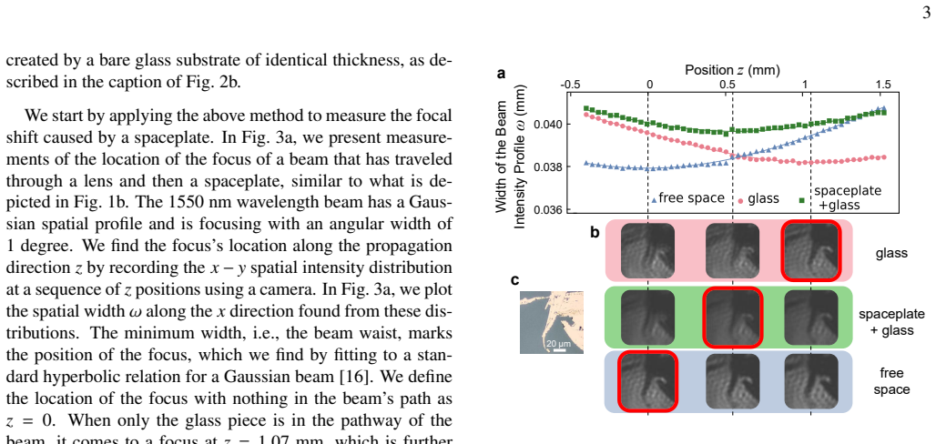
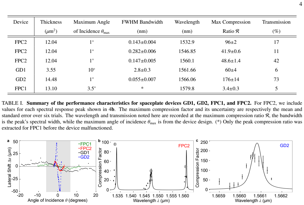
The central discovery is that a multilayer stack can be engineered to produce the nonlocal phase response of free space: the angular derivative of its transmission phase creates a transverse beam shift that grows as $w = d_{\mathrm{eff}}\tan\theta$ over the device's operating window, so the stack effectively replaces a thickness $d_{\mathrm{eff}} = R\,d$ of empty space. The highest measured value is $R = 176\pm14$, obtained by fitting the lateral shift of a focused beam through the 14.48-micron GD2 device at 1566.06 nm; the same fitting procedure gives $R = 60\pm4$ for the larger-angle GD1 design and $R = 41.9\pm0.6$ at one of the FPC2 resonances. In an imaging geometry, the 12.04-micron FPC2 device shortens the focal distance by 0.50 mm ($R \approx 43$) and the image stays sharp at the new plane, demonstrating a genuine compaction of an imaging system rather than just a beam displacement.
Load-bearing premise
The measured compression ratio is obtained by subtracting the lateral shift of a bare fused-silica substrate from the shift of the multilayer-on-glass sample, and this assumes the coated and bare substrates are identical in thickness, flatness, and stress state; a small mismatch would directly bias the fitted R.
Editorial extensions
If this is right
- Multilayer spaceplates can be fabricated with established commercial thin-film deposition, so the demonstrated effect does not rely on bespoke nanofabrication.
- The measured tradeoffs between angular range, bandwidth, and compression ratio (GD2 reaches R = 176 with a 1-degree range and 0.055 nm bandwidth, while GD1 reaches 10 degrees with R = 60 and 2.8 nm bandwidth) mean a device can be tailored to a specific application.
- Inserting a spaceplate behind a lens shortens the distance to the focus without changing magnification, so optical systems can be compacted without altering image scale.
- A high-R spaceplate can cancel the beam walk-off of a much thicker glass plate (the 11.51-micron FPC2 cancels the walk-off of a 3-mm glass plate that is 260 times thicker), which is useful for beam splitters and advanced imaging systems.
- The narrowband resonances that accompany high compression are naturally matched to LIDAR and retinal scanners, which operate at fixed laser lines.
Reading between the lines
- Editorial inference: if the substrate-subtraction assumption holds, the same design approach should push R higher by adding more layers; the practical limits will come from material loss, dispersion, and fabrication tolerances rather than the concept itself.
- Editorial inference: the focal-shift and lateral-shift methods yield compatible R values on the same device family, but not yet on the same device at the same wavelength; measuring both on one sample would strengthen the identification of R as an intrinsic device property.
- Editorial inference: the nonlocal phase description suggests the same stacks could be used as spatial filters or beam displacers beyond spaceplate applications, since the lateral-shift mechanism is the same one that produces large Goos-Hanchen-like displacements in narrowband multilayer filters.
- Editorial inference: replacing the fused-silica substrate with a lighter or curved carrier, or co-integrating the stack directly onto a lens or sensor, is a natural next step that the current proof-of-principle does not yet demonstrate.
Signed reviews
Editorial analysis
A structured set of objections, weighed in public.
Referee Report
Summary. The paper reports multilayer-stack optical spaceplates operating near 1550 nm, fabricated from alternating a-Si:H and SiO2 layers. Two design families are tested (gradient-descent GD1/GD2 and Fabry-Perot-cavity FPC1/FPC2), and the compression ratio R is extracted from lateral beam shifts versus angle using Eq. (1). The authors report a maximum R = 176 ± 14 for GD2 at 1566.06 nm, claim this is the highest compression ratio yet demonstrated in any wavelength region, and support the result with a focal-shift measurement (0.50 mm shortening for FPC2) and an imaging demonstration. The paper includes transfer-matrix-model comparisons for R(λ) and transmission spectra.
Significance. If the record compression ratios are correct, the work is significant because it moves spaceplates from bulky or crystalline demonstrations to a commercial multilayer platform with designable bandwidth and angular range. The strength of the paper is the clean lateral-shift fitting procedure and the multi-wavelength transfer-matrix comparison, as well as the focal-shift and imaging cross-checks. However, all three experimental validations rest on the same glass-substrate subtraction method, whose systematic uncertainties are not quantified, and the internal performance tables are inconsistent. The central quantitative claim therefore requires additional evidence before it can be taken as established.
major comments (3)
- [Methods, Measurement of the lateral beam shift; SI, Fabrication Details and Analysis] The isolation of the spaceplate lateral shift Δx_sp from the measured Δx_gl+sp − Δx_gl assumes that the bare fused-silica substrate is identical to the coated substrate in thickness, flatness, and stress state. The SI lists substrate thicknesses (3.03 mm for FPC1, FPC2, GD2; 2.95 mm for GD1) but gives no tolerance, no flatness measurement, and no statement that the uncoated reference was a matched witness from the same batch. A systematic thickness mismatch or curvature difference enters directly into Δx_sp and therefore into the fitted R for every device. The quoted uncertainty (±14 for GD2) is only the standard error over six trials and does not include this systematic. The focal-shift and imaging checks use the same glass-subtraction logic, so they do not independently validate R. This is load-bearing for the central claim of record compression, R = 176 ± 14.
- [SI, Table II] Table II contains internally inconsistent effective lengths and compression factors. For FPC2, 767/12.04 = 63.7, not 43.0; for GD2, 3196/14.48 = 220.7, not 238.2; for GD1, 44.7/3.55 = 12.6, not 18.0; for FPC1, 43.76/13.10 = 3.34, not 3.368. Furthermore, Table II disagrees with Table I on the measured compression ratios (e.g., GD1: 18.0 vs 60 ± 4; GD2: 238.2 vs 176 ± 14; FPC1: 3.368 vs 3.4 ± 0.3; FPC2 central: 43.0 vs 41.9 ± 0.6). The authors must clarify which column is simulated versus measured and correct the arithmetic, since these tables are the basis for the claimed record and for the design-versatility conclusions.
- [Fig. 4a caption; Table I; Results (section 'A comparison of the performance of the different spaceplate designs')] The reported value for GD1 is inconsistent across the manuscript. The Fig. 4a caption states R(GD1) = 30 ± 3 (black curve), while Table I and the main text report R = 60 ± 4 for GD1. This discrepancy affects the trade-off discussion and the summary of device performance. The authors should identify which value corresponds to the fit shown in Fig. 4a and which to the peak spectral value in Table I, and ensure all three locations agree.
minor comments (5)
- [Table I] The header 'Thickness (µm2)' should read 'µm'; the superscript 2 appears to be a typographical error.
- [Observation of the focal shift; Fig. 3a; Table I] The text states that 'the 11.51 µm-thick spaceplate shortens the focal distance by 0.50 mm', but Table I lists FPC2 as 12.04 µm thick. With 0.50 mm and 12.04 µm the implied R is about 41.5, whereas with 11.51 µm it is about 43.4; please make the thickness consistent.
- [Fig. 4a] The caption says 'The shaded region indicates the GD2's angular range from −θmax to +θmax as an example', but the main text (Results) refers to 'the shaded area for GD1 as an example'. Clarify which device is shown.
- [Introduction and Results] There are several typographical errors, including 'spacelate' (Results), 'di fferent' (Introduction), and 'the, the FPC design' (Introduction). These should be corrected during revision.
- [SI, Eq. (3) and text around Fig. 6] The statement 'the device, as depicted by its unit cell in Fig. 6 d.' should be 'Fig. 6d' to match the figure label style; also, the relation between the fitted phase in Eq. (3) and the measured R in Table I should be stated explicitly.
Circularity Check
No significant circularity; the compression ratio is extracted from direct lateral-shift measurements and independently corroborated by a parameter-free TMM model and focal-shift observations.
full rationale
The central claim, R up to 176, is obtained by fitting the measured lateral beam shift as a function of incidence angle to Eq. (1), Δx = -(R-1)d sinθ, over the designed angular range (Fig. 4a and Methods). The fitted slope directly determines R, so the measurement does not presuppose the value being claimed. The spectral dependence shown in Fig. 4b,c compares these measured R(λ) values against a transfer-matrix-method simulation of the multilayer stack using the known layer thicknesses and literature refractive indices; the model is not fitted to the experimental R, so the comparison is an independent cross-check rather than a restatement of the input. The focal-shift and imaging demonstrations similarly provide independent physical manifestations of the spaceplate action, even though they share the same bare-substrate subtraction logic. Citations to prior work by overlapping authors, including the original spaceplate concept, the inverse-design algorithm, and performance limits, are normal scientific attribution; no load-bearing premise reduces to an unverified self-citation or an imported uniqueness theorem. The main experimental weakness, namely the absence of a stated tolerance for the bare fused-silica substrate subtraction, is a systematic-error and robustness concern, not a circularity of definition, fitting, or prediction. No step of the paper defines its target quantity in terms of that same quantity or renames a fit as an independent prediction.
Assumptions & free parameters
assumptions (5)
- standard math Free-space propagation can be modeled as an angular-spectrum phase phi_SP = k n_BG deff cos(theta) (SI Eq. 3).
- domain assumption The multilayer stack's optical response is accurately described by the transfer-matrix method using bulk indices (n_H=3.2, n_L=1.456) and nominal layer thicknesses.
- standard math The lateral beam shift is given by delta_x = -(1/(k cos(theta))) dphi_t/dtheta (SI Eq. 2), the stationary-phase/Goos-Haenchen relation.
- domain assumption Subtracting the shift of a bare glass substrate from the shift of the spaceplate-on-glass sample isolates the multilayer contribution.
- standard math Within +/-theta_max the lateral shift follows the small-angle form delta_x approx -(R-1)d sin(theta), so a linear fit gives R.
Cite this review
Pith. "Pith review of Experimental demonstration of high compression of space by optical spaceplates." pith.science (2026). https://pith.science/paper/IZZOSDG7
@misc{pith2026250620647,
  author       = {Pith},
  title        = {Pith review of: Experimental demonstration of high compression of space by optical spaceplates},
  year         = {2026},
  howpublished = {\url{https://pith.science/paper/IZZOSDG7}},
  note         = {Machine review of arXiv:2506.20647}
}
abstract
The physical size of optical imaging systems is one of the greatest constraints on their use, limiting the performance and deployment of a range of systems from telescopes to mobile phone cameras. Spaceplates are nonlocal optical devices that compress free-space propagation into a shorter distance, paving the way for more compact optical systems, potentially even thin flat cameras. Here, we demonstrate the first engineered optical spaceplate and experimentally observe the highest space compression ratios yet demonstrated in any wavelength region, up to $\mathcal{R}=176\pm14$, which is 29 times higher than any previous device. Our spaceplate is a multilayer stack, a well-established commercial fabrication technology that supports mass production. The versatility of these stacks allows for the freedom to customize the spaceplate's bandwidth and angular range, impossible with previous optical experimental spaceplates, which were made of bulk materials. With the appropriate choice of these two parameters, multilayer spaceplates have near-term applications in light detection and ranging (LIDAR) technologies, retinal scanners, endoscopes, and other size-constrained optical devices.
Figures


Figures from the paper (5 more)


Reference graph
Works this paper leans on
-
[1]
Space squeezing optics: Performance limits and implementation at microwave frequencies,
Mrnka, Michal, Hendry, Euan, L ´aˇc´ık, Jaroslav, Lennon, Rachel A., Barr, Lauren E., Hooper, Ian, Phillips, David B., “Space squeezing optics: Performance limits and implementation at microwave frequencies,” APL Photonics , vol. 7, no. 7, pp. 076105, 2022
work page 2022
-
[2]
Flat optics with designer metasurfaces,
Yu, Nanfang, Capasso, Federico, “Flat optics with designer metasurfaces,” Nature Materials, vol. 13, no. 2, pp. 139–150, 2014
work page 2014
-
[3]
Pla- nar Diffractive Lenses: Fundamentals, Functionalities, and Ap- plications,
Huang, Kun, Qin, Fei, Liu, Hong, Ye, Huapeng, Qiu, Cheng- Wei, Hong, Minghui, Luk’yanchuk, Boris, Teng, Jinghua, “Pla- nar Diffractive Lenses: Fundamentals, Functionalities, and Ap- plications,” Advanced Materials, vol. 30, no. 26, pp. 1704556
-
[4]
Diffractive metalens: from fundamentals, practical applica- tions to current trends,
Liu, Wenwei, Cheng, Hua, Tian, Jianguo, Chen, Shuqi, “Diffractive metalens: from fundamentals, practical applica- tions to current trends,” Advances in Physics: X , vol. 5, no. 1, pp. 1742584, 2020
work page 2020
-
[5]
Miyamoto, Kenro, “The Phase Fresnel Lens,” J. Opt. Soc. Am. , vol. 51, no. 1, pp. 17–20, 1961
work page 1961
-
[6]
Flat optics for image di fferentiation,
Zhou, You, Zheng, Hanyu, Kravchenko, Ivan I, Valentine, Ja- son, “Flat optics for image di fferentiation,” Nature Photonics, vol. 14, no. 5, pp. 316–323, 2020
work page 2020
-
[7]
Broadband transparent and CMOS-compatible flat optics with silicon ni- tride metasurfaces,
Colburn, Shane, Zhan, Alan, Bayati, Elyas, Whitehead, James, Ryou, Albert, Huang, Luocheng, Majumdar, Arka, “Broadband transparent and CMOS-compatible flat optics with silicon ni- tride metasurfaces,” Optical Materials Express , vol. 8, no. 8, pp. 2330–2344, 2018
work page 2018
-
[8]
An optic to replace space and its application towards ultra-thin imaging systems,
Reshef, Orad, DelMastro, Michael P, Bearne, Katherine KM, Alhulaymi, Ali H, Giner, Lambert, Boyd, Robert W, Lundeen, Jeff S, “An optic to replace space and its application towards ultra-thin imaging systems,” Nature Communications, vol. 12, no. 1, pp. 1–8, 2021
work page 2021
Show all 23 references
-
[9]
Squeeze free space with nonlocal flat optics,
Guo, Cheng, Wang, Haiwen, Fan, Shanhui, “Squeeze free space with nonlocal flat optics,” Optica, vol. 7, no. 9, pp. 1133–1138, 2020
2020
-
[10]
Designing high-performance propagation-compressing spaceplates using thin-film multilayer stacks,
Pag ´e, Jordan TR, Reshef, Orad, Boyd, Robert W, Lundeen, Jeff S, “Designing high-performance propagation-compressing spaceplates using thin-film multilayer stacks,” Optics Express, vol. 30, no. 2, pp. 2197–2205, 2022
2022
-
[11]
Dielectric nonlocal meta- surfaces for fully solid-state ultrathin optical systems,
Chen, Aobo, Monticone, Francesco, “Dielectric nonlocal meta- surfaces for fully solid-state ultrathin optical systems,” ACS Photonics, vol. 8, no. 5, pp. 1439–1447, 2021
2021
-
[12]
Broadband transparent Huygens spaceplates,
D ´ıaz-Fern´andez, Francisco, M´a˜nez-Espina, Luis Manuel, D´ıaz- Rubio, Ana, Asadchy, Viktar, “Broadband transparent Huygens spaceplates,” npj Nanophotonics, 2024
2024
-
[13]
To what extent can space be com- pressed? Bandwidth limits of spaceplates,
Shastri, Kunal, Reshef, Orad, Boyd, Robert W, Lundeen, Je ff S, Monticone, Francesco, “To what extent can space be com- pressed? Bandwidth limits of spaceplates,”Optica, vol. 9, no. 7, pp. 738–745, 2022
2022
-
[14]
Why optics needs thickness,
Miller, David AB, “Why optics needs thickness,” Science, vol. 379, no. 6627, pp. 41–45, 2023
2023
-
[15]
Large- scale optical compression of free-space using an experimen- tal three-lens spaceplate,
Sorensen, Nicholas J, Weil, Michael T, Lundeen, Jeff S, “Large- scale optical compression of free-space using an experimen- tal three-lens spaceplate,” Optics Express , vol. 31, no. 12, pp. 19766–19776, 2023
2023
-
[16]
313, 1991
Saleh, Bahaa E, Teich, Malvin C, Fundamentals of Photonics , Wiley, pp. 313, 1991
1991
-
[17]
An angular spectrum representation approach to the Goos-H ¨anchen shift,
McGuirk, Michael, Carniglia, Charles K, “An angular spectrum representation approach to the Goos-H ¨anchen shift,” JOSA, vol. 67, no. 1, pp. 103–107, 1977
1977
-
[18]
Multilayer thin-film struc- tures with high spatial dispersion,
Gerken, Martina, Miller, David AB, “Multilayer thin-film struc- tures with high spatial dispersion,” Applied Optics , vol. 42, no. 7, pp. 1330–1345, 2003
2003
-
[19]
Beam displacement and distortion e ffects in narrowband optical thin-film filters,
Klinger, Robert E, Hulse, Charles A, Carniglia, Charles K, Sar- gent, Robert B, “Beam displacement and distortion e ffects in narrowband optical thin-film filters,” Applied Optics , vol. 45, no. 14, pp. 3237–3242, 2006
2006
-
[20]
Spectral imaging and spectral LIDAR systems: Moving toward compact nanophotonics-based sensing,
Li, Nanxi, Ho, Chong Pei, Wang, I-Ting, Pitchappa, Prakash, Fu, Yuan Hsing, Zhu, Yao, Lee, Lennon Yao Ting, “Spectral imaging and spectral LIDAR systems: Moving toward compact nanophotonics-based sensing,” Nanophotonics, vol. 10, no. 5, pp. 1437–1467, 2021
2021
-
[21]
Construct a polarizing beam splitter by an anisotropic metamaterial slab,
Luo, H, Ren, Z, Shu, W, Li, F, “Construct a polarizing beam splitter by an anisotropic metamaterial slab,” Applied Physics B, vol. 87, pp. 283–287, 2007
2007
-
[22]
Polarization-dependent all- dielectric metasurface for single-shot quantitative phase imag- ing,
Engay, Einstom, Huo, Dewang, Malureanu, Radu, Bunea, Ada-Ioana, Lavrinenko, Andrei, “Polarization-dependent all- dielectric metasurface for single-shot quantitative phase imag- ing,” Nano Letters, vol. 21, no. 9, pp. 3820–3826, 2021
2021
-
[23]
Modeling and evaluation of the systematic errors for the polarization-sensitive imaging lidar technique,
Kong, Zheng, Yin, Zhenping, Cheng, Yuan, Li, Yichen, Zhang, Zhen, Mei, Liang, “Modeling and evaluation of the systematic errors for the polarization-sensitive imaging lidar technique,” Remote Sensing, vol. 12, no. 20, pp. 3309, 2020. 7 Supplementary Information Design and Char...
2020
Reviewed August 6, 2026 · model on record in the stance chip above.
Discussion (0). Continue with ORCID to comment.