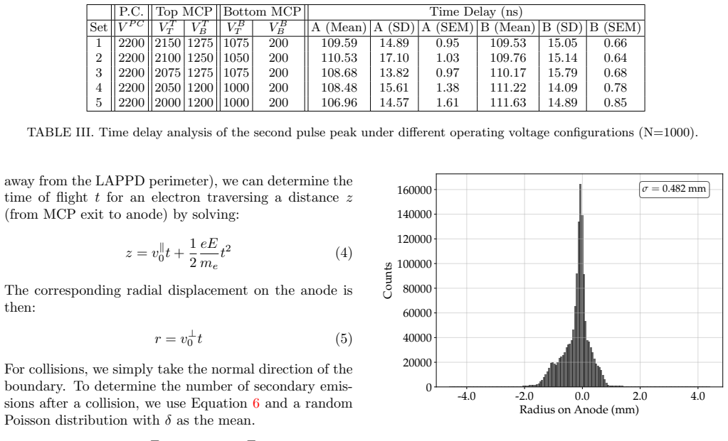
Operational characterization of LAPPD Generation 2: charge sharing, delayed pulses, and dark-count behavior
Pith reviewed 2026-06-26 15:35 UTC · model grok-4.3
The pith
A Monte Carlo simulation reproduces the pulse classifications derived from LAPPD Generation 2 measurements of charge sharing and delayed signals.
A machine-rendered reading of the paper's core claim, the machinery that carries it, and where it could break.
Core claim
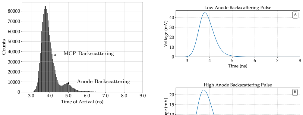
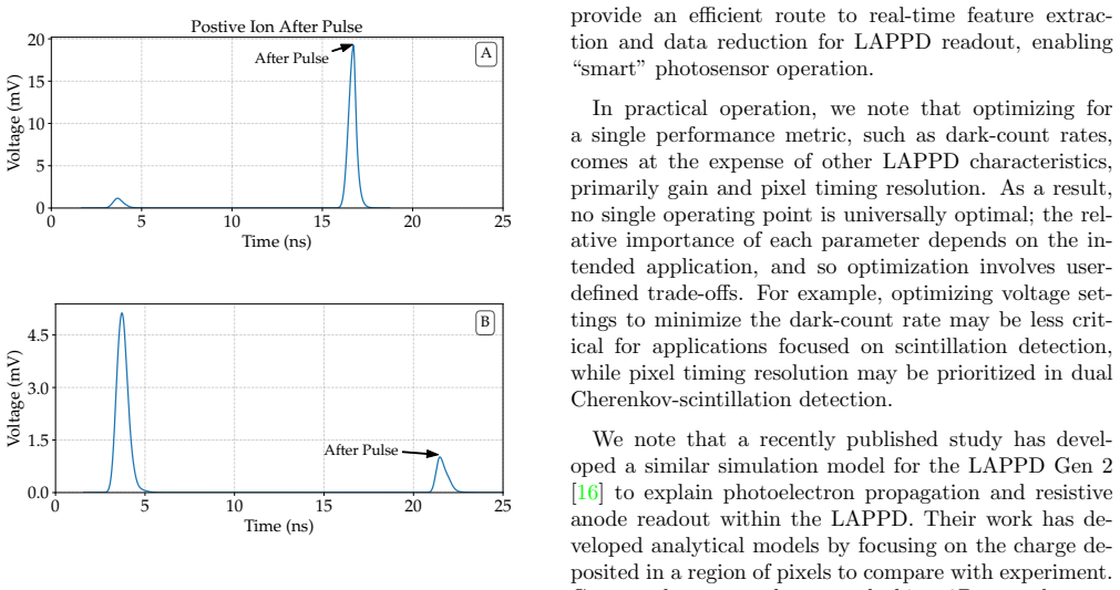
Using laser illumination and injected electrical pulses, the measurements establish quantitative charge sharing between the target pixel and its neighbors, identify fast, intermediate, and slow components in the dark-count decay, and confirm resonant-cavity behavior of the device. The pulse-classification method isolates additional delayed features at roughly 60 ns and 110 ns; the Monte Carlo simulation, incorporating radial and temporal propagation plus backscatter and afterpulsing contributions, reproduces the classified experimental distributions with reasonable agreement.
What carries the argument
The pulse-classification method that separates signals according to their apparent physical origins at approximately 60 ns and 110 ns, together with the first-principles Monte Carlo simulation of radial and temporal signal distributions.
If this is right
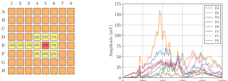
- Charge sharing and electronic cross-talk between the 8 by 8 pixels can be quantified directly from the spatial distribution of laser-induced signals.
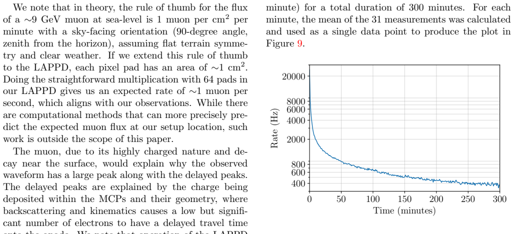
- Dark-count rates follow a decay characterized by three distinct relaxation timescales whose relative strengths depend on the applied voltages.
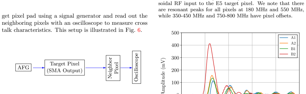
- The resistive anode and readout board together act as a resonant cavity when electrical pulses are injected.
- The delayed features at 60 ns and 110 ns arise from electron backscatter or ion afterpulsing and are reproduced by the simulation.
Where Pith is reading between the lines
- The classification and simulation approach could be used to correct for delayed pulses in timing analyses that rely on LAPPDs.
- Resonant-cavity behavior may limit the maximum rate at which clean single-photon signals can be recorded without ringing.
- If the model parameters are portable across devices, the simulation could predict performance changes when pixel size or anode resistivity is altered.
Load-bearing premise
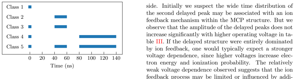
The pulse-classification method correctly identifies and separates the physical origins of the observed signals at approximately 60 ns and 110 ns without significant misclassification.
What would settle it
An independent data set in which the measured radial and temporal distributions of the 60 ns and 110 ns pulses deviate markedly from the Monte Carlo predictions once electron-backscatter and ion-afterpulsing terms are removed or their parameters are varied.
Figures

read the original abstract
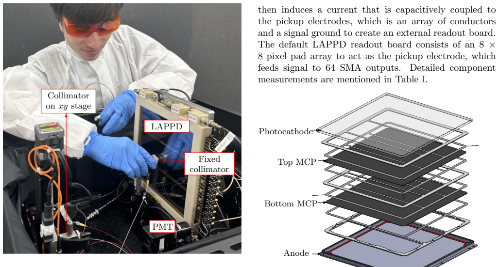
We present a study of charge sharing and electronic cross-talk in second-generation Large-Area Picosecond Photodetectors (LAPPD Gen 2). The LAPPD is a vacuum-based device consisting of a photocathode, two microchannel plates, and a resistive anode that capacitively couples to an 8 $\times$ 8 pixelated readout board (25.4 mm $\times$ 25.4 mm pixel area). Using a picosecond pulsed laser, we measure signal distributions across the resistive anode and quantify coupling between target and neighboring pixels. We further examine the relationship between dark-count rate and LAPPD voltage settings, identifying decay behavior characterized by fast, intermediate, and slow relaxation timescales. We additionally observe the LAPPD behaving as a resonant cavity by injecting electrical pulses into the readout board. To further interpret observed signals, we develop a pulse-classification method and identify additional features at approximately 60 ns and 110 ns. Finally, we implement a first-principles Monte Carlo simulation to model the radial and temporal distributions of observed signals, including contributions from electron backscatter and potential ion afterpulsing. The simulation shows reasonable agreement with the experimentally derived pulse classifications.
Editorial analysis
A structured set of objections, weighed in public.
Referee Report
Summary. The manuscript reports experimental characterization of LAPPD Generation 2 devices, including charge sharing and cross-talk measurements with a picosecond pulsed laser across an 8x8 pixelated resistive anode readout, dark-count rate dependence on voltage settings with identification of fast/intermediate/slow relaxation timescales, resonant cavity behavior via electrical pulse injection, development of a pulse-classification method that isolates additional delayed-pulse features at ~60 ns and ~110 ns, and comparison to a first-principles Monte Carlo simulation incorporating electron backscatter and ion afterpulsing that reproduces the classified radial and temporal signal distributions with reasonable agreement.
Significance. If the results hold, the work supplies practical operational data on charge sharing, cross-talk, and dark-count dynamics for LAPPDs, which are relevant for precision timing detectors. The first-principles Monte Carlo (no fitted parameters reported) provides an independent cross-check of the physical origins assigned to the delayed pulses, strengthening the pulse-classification method. Explicit inclusion of mechanisms such as backscatter and afterpulsing without post-hoc tuning to the data classifications is a clear strength.
minor comments (3)
- [Abstract] Abstract: the phrase 'reasonable agreement' between simulation and pulse classifications would benefit from a quantitative metric (e.g., Kolmogorov-Smirnov distance or binned χ^{2}) to allow readers to assess the level of agreement directly.
- The description of the pulse-classification method would be clearer if the decision criteria (timing windows, amplitude thresholds, or waveform shape parameters) were summarized in a table or flowchart rather than solely in prose.
- Figure captions should explicitly state the number of events or laser shots per distribution and whether error bars represent statistical or systematic uncertainties.
Simulated Author's Rebuttal
We thank the referee for the positive assessment of our work on LAPPD Gen 2 characterization, including the value placed on the laser-based measurements, dark-count analysis, resonant behavior observations, pulse classification, and the parameter-free Monte Carlo simulation. The recommendation for minor revision is noted; we will address any editorial or minor points in the revised version.
Circularity Check
No significant circularity detected
full rationale
The paper's core contributions are direct experimental measurements of charge sharing, cross-talk, dark-count relaxation, and resonant-cavity behavior, followed by a data-driven pulse-classification procedure whose outputs are then compared against an independent first-principles Monte Carlo model that incorporates explicit physical mechanisms (electron backscatter, ion afterpulsing). No equation or procedure is shown to define its own target quantity by construction, no fitted parameter is relabeled as a prediction, and the Monte Carlo is not described as having been tuned to the classification results. The derivation chain therefore remains self-contained against external benchmarks.
Axiom & Free-Parameter Ledger
Reference graph
Works this paper leans on
-
[1]
Their work has de- veloped analytical models by focusing on the charge de- posited in a region of pixels to compare with experiment
to explain photoelectron propagation and resistive anode readout within the LAPPD. Their work has de- veloped analytical models by focusing on the charge de- posited in a region of pixels to compare with experiment. Compared to our study, we worked in a 2D case where we used Monte Carlo simulations to look at the secondary electron distribution onto the r...
-
[2]
Continuous channel electron multiplier,
G. W. Goodrich and W. C. Wiley, “Continuous channel electron multiplier,” Review of Scientific Instruments 33, 761–762 (1962)
1962
-
[3]
A new water-based liquid scintillator and potential applications,
M. Yeh, S. Hans, W. Beriguete, R. Rosero, L. Hu, R. L. Hahn, M. V. Diwan, D. E. Jaffe, S. H. Kettell, and L. Littenberg, “A new water-based liquid scintillator and potential applications,” Nucl. Instrum. Meth. A 660, 51– 56 (2011)
2011
-
[4]
Measuring directionality in double-beta de- cay and neutrino interactions with kiloton-scale scintilla- tion detectors,
C Aberle, A Elagin, H J Frisch, M Wetstein, and L Winslow, “Measuring directionality in double-beta de- cay and neutrino interactions with kiloton-scale scintilla- tion detectors,” JINST 9, P06012 (2014)
2014
-
[5]
Deploy- ment of Water-based Liquid Scintillator in the Acceler- ator Neutrino Neutron Interaction Experiment,
M. Ascencio-Sosa, Z. Bagdasarian, J. F. Beacom, M. Bergevin, M. Breisch, G. Caceres Vera, S. Dazeley, S. Doran, E. Drakopoulou, S. Edayath, et al. , “Deploy- ment of Water-based Liquid Scintillator in the Acceler- ator Neutrino Neutron Interaction Experiment,” JINST 19, P05070 (2024)
2024
-
[6]
Characterization of water-based liquid scintillator for cherenkov and scintillation separation,
J. Caravaca, B.J. Land, M. Yeh, and G.D Orebi Gann, “Characterization of water-based liquid scintillator for cherenkov and scintillation separation,” The European Physical Journal C 80 (2020)
2020
-
[7]
Cherenkov and scintillation separation in water-based liquid scintillator using an LAPPD,
T. Kaptanoglu, E.J. Callaghan, M. Yeh, and G.D. Orebi Gann, “Cherenkov and scintillation separation in water-based liquid scintillator using an LAPPD,” The European Physical Journal C 82 (2022)
2022
-
[8]
Theia: an advanced oiptical neutrino detector,
M. Askins, Z. Bagdasarian, N. Barros, E.W. Beier, E. Blucher, R. Bonventre, E. Callaghan, J. Caravaca, M. Diwan, S.T. Dye, et al., “Theia: an advanced oiptical neutrino detector,” The European Physical Journal C 80 (2020)
2020
-
[9]
Initial assess- ment of second generation of large-area picosecond pho- todetectors with multi-channel systems-on-a-chip read- out,
V. A. Li, O. A. Akindele, M. Bondin, S. R. Durham, J. A. Foot, M. J. Ford, and S.-W. Stradleigh, “Initial assess- ment of second generation of large-area picosecond pho- todetectors with multi-channel systems-on-a-chip read- out,” Review of Scientific Instruments96, 113102 (2025)
2025
-
[10]
Characterization of LAPPD timing at CERN PS testbeam,
Deb Sankar Bhattacharya et al. , “Characterization of LAPPD timing at CERN PS testbeam,” Nucl. In- strum. Meth. A 1058, 168937 (2024), arXiv:2309.15011 [physics.ins-det]
arXiv 2024
-
[11]
R. L. Bell, Negative electron affinity devices (Claredon Press, Oxford, 1973)
1973
-
[12]
Hamamatsu, Photomultiplier Tubes, Basics and Applica- tions, Fourth Edition (2017)
2017
-
[13]
After- pulses in photomultipliers,
G. A. Morton, H. M. Smith, and R. Wasserman, “After- pulses in photomultipliers,” IEEE Transactions on Nu- clear Science 14, 443–448 (1967)
1967
-
[14]
Possible effects of photomultiplier- afterpulses on scintillation counter measurements,
R. Staubert, E. B¨ ohm, K. Hein, K. Sauerland, and J. Tr¨ umper, “Possible effects of photomultiplier- afterpulses on scintillation counter measurements,” Nu- clear Instruments and Methods 84, 297–300 (1970)
1970
-
[15]
Reduction of afterpulsing in a photomultiplier,
S.J. Hall and J. McKeown, “Reduction of afterpulsing in a photomultiplier,” Nuclear Instruments and Methods 112, 545–549 (1973)
1973
-
[16]
A study on ion initi- ated photomultiplier afterpulses,
Nural Akchurin and Heejong Kim, “A study on ion initi- ated photomultiplier afterpulses,” Nuclear Instruments and Methods in Physics Research Section A: Acceler- ators, Spectrometers, Detectors and Associated Equip- ment 574, 121–126 (2007)
2007
-
[17]
Characterisation of the LAPPD, a large area microchannel-plate PMT,
S. Korpar, R. Dolenec, F. Grijalva, A. Lozar, A. Kodriˇ c, P. Kriˇ zan, S. Parashari, R. Pestotnik, A. Seljak, and D. ˇZontar, “Characterisation of the LAPPD, a large area microchannel-plate PMT,” (2025), arXiv:2512.02990 [physics.ins-det]. APPENDIX [mm] 1 2 3 4 5 6 7 8 A 24 40 67 91 91 66 37 23 B 4 49 86 102 104 89 48 28 C 22 60 80 108 82 80 60 25 D 25 5...
arXiv 2025
discussion (0)
Sign in with ORCID, Apple, or X to comment. Anyone can read and Pith papers without signing in.