Negative Resistance Caused by Intra-Loop Coupling in Virtual-Admittance-Based Grid-Forming Control
Pith reviewed 2026-06-30 09:20 UTC · model grok-4.3
The pith
Intra-loop coupling among virtual-admittance control, current control, and voltage feedforward produces an s-squared term in inverter output impedance that creates negative resistance at harmonics independent of control delay.
A machine-rendered reading of the paper's core claim, the machinery that carries it, and where it could break.
Core claim
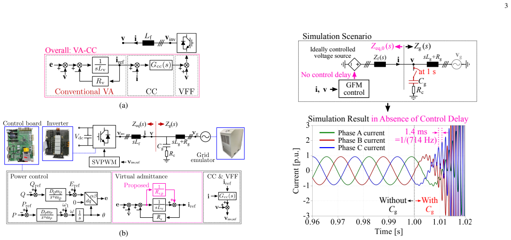
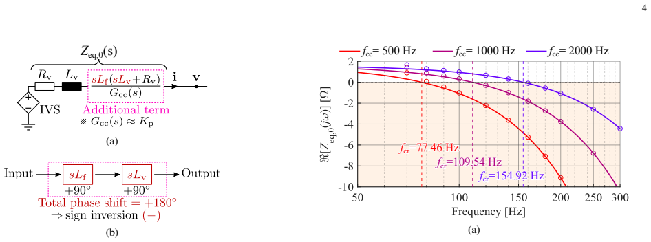
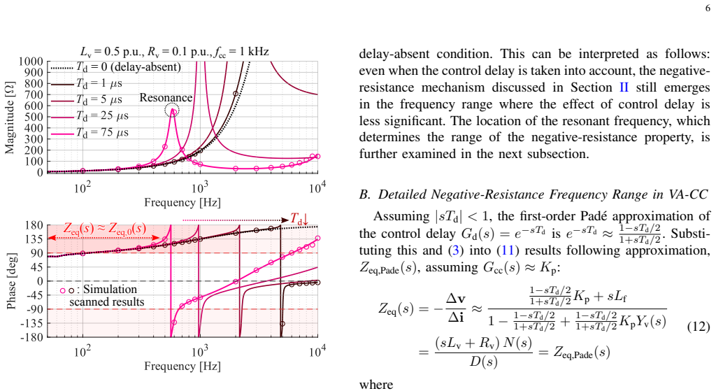
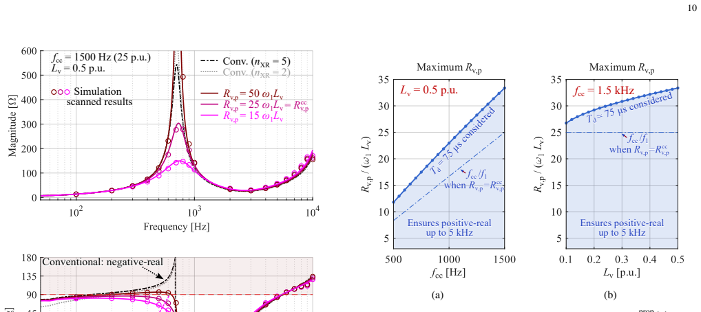
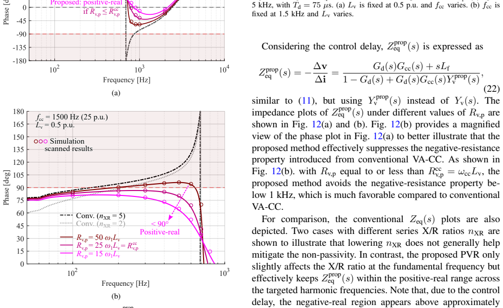
The intra-loop coupling among the VA control, the inner-loop current control, and the voltage feedforward control results in an s^2-term in the equivalent output impedance of the inverter, which induces a negative-resistance property in the harmonic range. This negative resistance is independent of the control delay. Consequently, this harmonic instability mechanism is fundamentally different from the extensively investigated cases in the literature, which are induced by the digital control delay of inverters. A simple passivity-oriented damping control is proposed to mitigate the negative resistance arising from the intra-loop coupling without requiring grid impedance information.
What carries the argument
The equivalent output impedance obtained from small-signal modeling of the three coupled loops, whose s-squared term supplies the negative real part at harmonic frequencies.
If this is right
- The negative-resistance region remains even if control delay is eliminated, so conventional delay-mitigation methods cannot remove this instability source.
- The proposed damping controller restores passivity while preserving the original current loop and voltage feedforward structure.
- Stability analysis based solely on delay-induced negative resistance will miss this mechanism in VA-based grid-forming inverters.
- The damping solution does not require knowledge of grid impedance, allowing deployment without additional measurements.
Where Pith is reading between the lines
- Similar intra-loop coupling may exist in other multi-loop converter controls that combine admittance shaping with inner current regulation and feedforward paths.
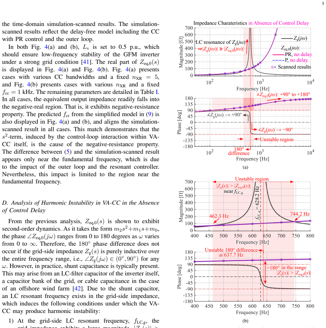
- The s-squared term could interact with grid resonances at specific harmonic frequencies, producing localized instability that only appears under certain grid conditions.
- Extending the impedance model to include PWM and sensor dynamics would test whether the negative-resistance prediction survives those additional lags.
Load-bearing premise
The small-signal model that yields the equivalent output impedance fully represents the closed-loop dynamics without unmodeled contributions from PWM or sensor dynamics.
What would settle it
An experimental frequency-response measurement of the inverter output impedance that shows no negative real part in the harmonic band when control delay is removed or compensated would falsify the claim that the intra-loop coupling produces delay-independent negative resistance.
Figures
read the original abstract
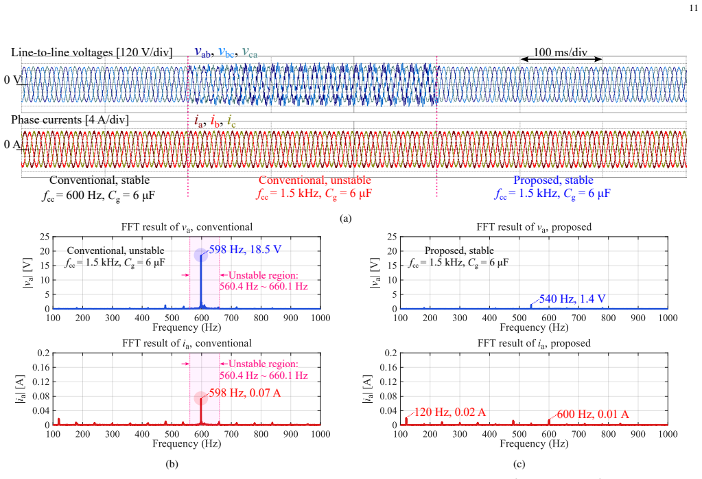
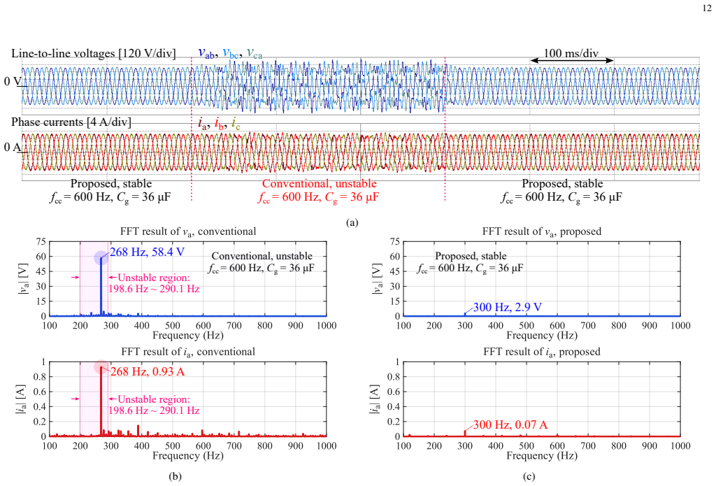
This paper addresses the harmonic instability problem of the virtual-admittance (VA)-based grid-forming control. It is revealed that the intra-loop coupling among the VA control, the inner-loop current control, and the voltage feedforward control results in an \(s^2\)-term in the equivalent output impedance of the inverter, which induces a negative-resistance property in the harmonic range. It is worth highlighting that this negative resistance is independent of the control delay. Consequently, this harmonic instability mechanism is fundamentally different from the extensively investigated cases in the literature, which are induced by the digital control delay of inverters. Then, a simple passivity-oriented damping control is proposed to mitigate the negative resistance arising from the intra-loop coupling. The method fully retains the well-established current controller and voltage feedforward, and does not require grid impedance information. Finally, experimental tests verify the theoretical findings and the effectiveness of the damping method.
Editorial analysis
A structured set of objections, weighed in public.
Referee Report
Summary. The manuscript analyzes harmonic instability in virtual-admittance (VA)-based grid-forming inverter control. It shows that intra-loop coupling among the VA controller, inner current loop, and voltage feedforward path produces an s² term in the closed-loop output impedance Z_out(s). This term creates a negative-resistance region in the harmonic frequency band and is asserted to be independent of digital control delay, distinguishing it from delay-induced mechanisms in the literature. A passivity-oriented damping controller is introduced to restore positive resistance while preserving the existing current controller and voltage feedforward paths and without requiring grid-impedance knowledge. Experimental results are cited to confirm both the impedance behavior and the damping effectiveness.
Significance. If the modeling and experimental evidence hold, the work identifies a previously under-examined source of negative resistance that is intrinsic to the control architecture rather than to delay. The proposed damping method is practically attractive because it is local, retains standard inner-loop structures, and avoids grid-parameter dependence. This could inform stability-oriented design of grid-forming inverters operating near weak grids or with high harmonic content.
major comments (2)
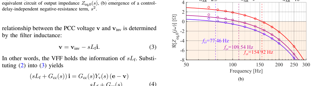
- [Small-signal modeling (Z_out derivation)] Small-signal modeling section (derivation of Z_out(s)): the block-diagram reduction yielding the s² coefficient in the output impedance treats the PWM as an ideal gain and the voltage/current sensors as unity. The stress-test concern is load-bearing: realistic PWM delay and sensor filtering enter the loop before the feedforward path and can change the sign of the s² term or introduce dominating higher-order dynamics in the 250–750 Hz range. The manuscript must demonstrate that the claimed negative-resistance property and its delay independence survive these additions; otherwise the distinction from delay-induced mechanisms is not secured.
- [Impedance analysis] Impedance analysis (expression for Re{Z_out(jω)} in harmonic band): the claim that the negative resistance arises solely from intra-loop coupling and is independent of control delay rests on the specific form of the s² term. Without an explicit comparison of the full closed-loop transfer function with and without the PWM/sensor blocks, it remains unclear whether the sign of the real part is robust or an artifact of the ideal-gain assumption.
minor comments (2)
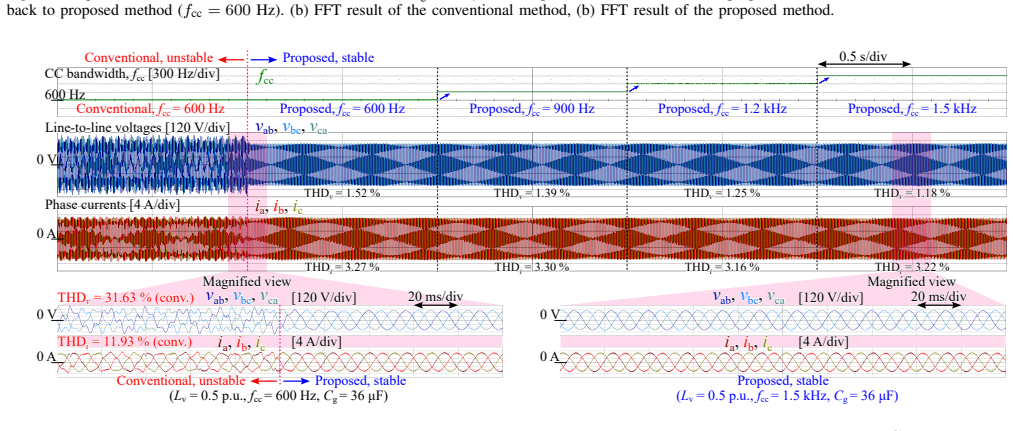
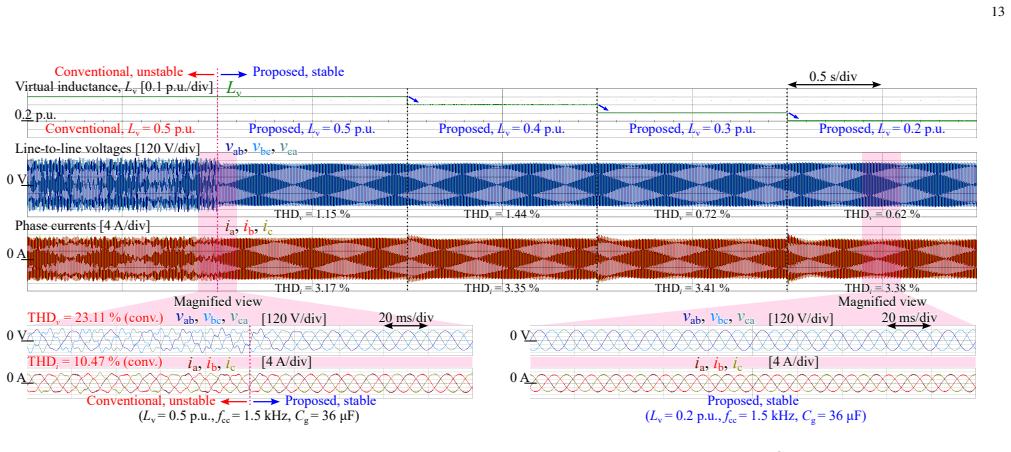
- [Experimental verification] The abstract states that experimental tests verify the findings, but the main text should include a brief description of the test setup (grid impedance, operating point, harmonic injection method) to allow readers to assess the generality of the results.
- [Control structure] Notation for the VA admittance and the damping gain should be introduced consistently when first appearing in the control diagram and in the impedance equations.
Simulated Author's Rebuttal
We thank the referee for the careful review and for identifying the need to strengthen the modeling assumptions in our analysis of intra-loop coupling. The comments are well-taken and have prompted us to extend the small-signal model. We respond to each major comment below and indicate the corresponding revisions.
read point-by-point responses
-
Referee: [Small-signal modeling (Z_out derivation)] Small-signal modeling section (derivation of Z_out(s)): the block-diagram reduction yielding the s² coefficient in the output impedance treats the PWM as an ideal gain and the voltage/current sensors as unity. The stress-test concern is load-bearing: realistic PWM delay and sensor filtering enter the loop before the feedforward path and can change the sign of the s² term or introduce dominating higher-order dynamics in the 250–750 Hz range. The manuscript must demonstrate that the claimed negative-resistance property and its delay independence survive these additions; otherwise the distinction from delay-induced mechanisms is not secured.
Authors: We agree that the original derivation used ideal PWM gain and unity-gain sensors. The s² term, however, is generated by the algebraic summation of the virtual-admittance current reference, the inner current controller output, and the voltage feedforward term; these operations occur upstream of both the PWM and the sensor paths. To verify robustness we have augmented the model with a first-order Padé approximation of the computational/PWM delay and first-order sensor filters. The revised closed-loop Z_out(s) retains a negative leading s² coefficient whose sign is unchanged in the 250–750 Hz band. The updated Section III now contains the extended block diagram, the modified transfer-function derivation, and numerical evaluations confirming that the negative-resistance region survives. This preserves the claimed distinction from purely delay-induced mechanisms. revision: yes
-
Referee: [Impedance analysis] Impedance analysis (expression for Re{Z_out(jω)} in harmonic band): the claim that the negative resistance arises solely from intra-loop coupling and is independent of control delay rests on the specific form of the s² term. Without an explicit comparison of the full closed-loop transfer function with and without the PWM/sensor blocks, it remains unclear whether the sign of the real part is robust or an artifact of the ideal-gain assumption.
Authors: The referee correctly notes the absence of an explicit side-by-side comparison. In the revised manuscript we derive the full closed-loop output impedance both with and without the PWM delay (e^{-sT_d}) and sensor filters, then plot Re{Z_out(jω)} for both cases over the harmonic range. The negative-resistance interval remains present in both models, with only small boundary shifts attributable to the additional phase lag. The comparison is now included as a new figure and accompanying equations in Section IV, directly addressing the concern and reinforcing that the sign of the real part is attributable to the intra-loop coupling rather than the ideal-gain simplification. revision: yes
Circularity Check
Derivation of s^2 term and negative resistance from intra-loop coupling is self-contained
full rationale
The paper obtains the s^2 term in the equivalent output impedance by reducing the block diagram of the VA control, inner current loop, and voltage feedforward path. The abstract states this coupling 'results in an s^2-term ... which induces a negative-resistance property' and notes the result is 'independent of the control delay.' No fitted parameters are introduced to produce the sign of the real part, no self-citation chain is used to justify the model structure, and the derivation is not shown to be equivalent to its inputs by construction. Standard small-signal assumptions (ideal PWM, unity sensors) are explicit modeling choices rather than tautological redefinitions. This is the normal non-circular outcome for a control-theoretic impedance derivation.
Axiom & Free-Parameter Ledger
axioms (1)
- domain assumption Small-signal modeling of the VA control, current loop, and voltage feedforward accurately captures the closed-loop output impedance.
Reference graph
Works this paper leans on
-
[1]
Grid forming inverter modeling, control, and applications,
D. B. Rathnayake, M. Akrami, C. Phurailatpam, S. P. Me, S. Hadavi, G. Jayasinghe, S. Zabihi, and B. Bahrani, “Grid forming inverter modeling, control, and applications,”IEEE Access, vol. 9, pp. 114 781– 114 807, 2021
2021
-
[2]
Modeling and control of grid forming converters: A systematic review,
M. Tozak, S. Taskin, I. Sengor, and B. P. Hayes, “Modeling and control of grid forming converters: A systematic review,”IEEE Access, vol. 12, pp. 107 818–107 843, 2024
2024
-
[3]
Grid forming converters in renewable energy sources dominated power grid: Control strategy, stability, application, and challenges,
H. Zhang, W. Xiang, W. Lin, and J. Wen, “Grid forming converters in renewable energy sources dominated power grid: Control strategy, stability, application, and challenges,”J. Mod. Power Syst. Clean Energy, vol. 9, no. 6, pp. 1239–1256, Nov. 2021
2021
-
[4]
Review of grid-forming inverters in support of power system operation,
G. Song, B. Cao, and L. Chang, “Review of grid-forming inverters in support of power system operation,”Chin. J. Electr. Eng., vol. 8, no. 1, pp. 1–15, Mar. 2022
2022
-
[5]
Grid-forming converters. A critical review of pilot projects and demonstrators,
R. Musca, A. Vasile, and G. Zizzo, “Grid-forming converters. A critical review of pilot projects and demonstrators,”Renew. Sustain. Energy Rev., vol. 165, Art. no. 112 551, 2022
2022
-
[6]
UNIFI specifications for grid-forming inverter- based resources—Version 3,
UNIFI Consortium, “UNIFI specifications for grid-forming inverter- based resources—Version 3,” Nat. Lab. Rockies (NLR), Golden, CO, USA, Tech. Rep. NLR/TP-5D00-98381, Jan. 2026
2026
-
[7]
Great Britain grid forming best practice guide,
National Grid ESO, “Great Britain grid forming best practice guide,” Iss. 3, NESO, U.K., 2023. [Online]. Available: https://www.neso.energy/ document/289921/download
2023
-
[8]
Passivity-based stability analysis and generic controller design for grid- forming inverter,
G. Wu, Y . He, H. Zhang, X. Wang, D. Pan, X. Ruan, and C. Yao, “Passivity-based stability analysis and generic controller design for grid- forming inverter,”IEEE Trans. Power Electron., vol. 38, no. 5, pp. 5832– 5843, May 2023
2023
-
[9]
Impact of voltage-loop feedforward terms on the stability of grid- forming inverters and remedial actions,
M. H. Ravanji, D. B. Rathnayake, M. Z. Mansour, and B. Bahrani, “Impact of voltage-loop feedforward terms on the stability of grid- forming inverters and remedial actions,”IEEE Trans. Energy Convers., vol. 38, no. 3, pp. 1554–1565, Sep. 2023
2023
-
[10]
Enhancing voltage control stability of grid-forming VSCs under PWM delays: A study on feedforward damping methods,
S. He, C. Gao, Z. Yang, H. Li, L. Ding, and F. Blaabjerg, “Enhancing voltage control stability of grid-forming VSCs under PWM delays: A study on feedforward damping methods,”IEEE Trans. Circuits Syst. I, Reg. Papers, vol. 72, no. 9, pp. 5233–5246, Sep. 2025
2025
-
[11]
Passivity-based control of single-loop grid-forming inverters,
A. Akhavan, J. C. Vasquez, and J. M. Guerrero, “Passivity-based control of single-loop grid-forming inverters,”IEEE J. Emerg. Sel. Topics Ind. Electron., vol. 4, no. 2, pp. 571–579, Apr. 2023
2023
-
[12]
Control of grid-connected power converters based on a virtual admittance control loop,
P. Rodriguez, I. Candela, C. Citro, J. Rocabert, and A. Luna, “Control of grid-connected power converters based on a virtual admittance control loop,” inProc. 15th Eur. Conf. Power Electron. Appl. (EPE), 2013, pp. 1–10
2013
-
[13]
Grid-forming controller based on virtual admittance for power convert- ers working in weak grids,
J. D. V . Leon, A. Tarras ´o, J. I. Candela, J. Rocabert, and P. Rodriguez, “Grid-forming controller based on virtual admittance for power convert- ers working in weak grids,”IEEE J. Emerg. Sel. Topics Ind. Electron., vol. 4, no. 3, pp. 791–801, Jul. 2023
2023
-
[14]
Grid voltage harmonic damping method for SPC based power converters with multi- ple virtual admittance control,
A. Tarras ´o, J. I. Candela, J. Rocabert, and P. Rodriguez, “Grid voltage harmonic damping method for SPC based power converters with multi- ple virtual admittance control,” inProc. IEEE Energy Convers. Congr. Expo. (ECCE), 2017, pp. 64–68
2017
-
[15]
Virtual admittance based modeling and stability analysis of grid-forming inverter under Clarke transformation,
B. Cui, L. Huang, C. Gao, and P. C. Loh, “Virtual admittance based modeling and stability analysis of grid-forming inverter under Clarke transformation,” inProc. IECON 2024 – 50th Annu. Conf. IEEE Ind. Electron. Soc., 2024, pp. 1–6
2024
-
[16]
Impact of virtual admittance on small-signal stability of grid-forming inverters,
L. Huang, C. Wu, D. Zhou, and F. Blaabjerg, “Impact of virtual admittance on small-signal stability of grid-forming inverters,” inProc. 6th IEEE Workshop Electron. Grid (eGRID), 2021, pp. 1–8
2021
-
[17]
Frequency-based virtual-admittance tuning for grid-forming convert- ers,
P. Imgart, M. B. Beza, M. Bongiorno, J. R. Svensson, and J.-P. Hasler, “Frequency-based virtual-admittance tuning for grid-forming convert- ers,”Electr. Power Syst. Res., 2026
2026
-
[18]
Physical interpretations of grid voltage full feedforward for grid-tied inverter,
Y . Xiong and Y . Ye, “Physical interpretations of grid voltage full feedforward for grid-tied inverter,”IEEE Trans. Circuits Syst. II, Express Briefs, vol. 66, no. 2, pp. 267–271, Feb. 2019
2019
-
[19]
Capacitor-voltage feedfor- ward with full delay compensation to improve weak grids adaptability of LCL-filtered grid-connected converters for distributed generation systems,
X. Li, J. Fang, Y . Tang, X. Wu, and Y . Geng, “Capacitor-voltage feedfor- ward with full delay compensation to improve weak grids adaptability of LCL-filtered grid-connected converters for distributed generation systems,”IEEE Trans. Power Electron., vol. 33, no. 1, pp. 749–764, Jan. 2018
2018
-
[20]
An improved grid-voltage feedforward strategy for high-power three-phase grid-connected invert- ers based on the simplified repetitive predictor,
Q. Yan, X. Wu, X. Yuan, and Y . Geng, “An improved grid-voltage feedforward strategy for high-power three-phase grid-connected invert- ers based on the simplified repetitive predictor,”IEEE Trans. Power Electron., vol. 31, no. 5, pp. 3880–3897, May 2016
2016
-
[21]
A full-feedforward scheme of grid voltages for a three-phase grid-connected inverter with an LCL filter,
W. Li, D. Pan, X. Ruan, and X. Wang, “A full-feedforward scheme of grid voltages for a three-phase grid-connected inverter with an LCL filter,” inProc. IEEE Energy Convers. Congr. Expo. (ECCE), 2011, pp. 96–103
2011
-
[22]
A robust grid- voltage feedforward scheme to improve adaptability of grid-connected inverter to weak grid condition,
X. Wang, K. Qin, X. Ruan, D. Pan, Y . He, and F. Liu, “A robust grid- voltage feedforward scheme to improve adaptability of grid-connected inverter to weak grid condition,”IEEE Trans. Power Electron., vol. 36, no. 2, pp. 2384–2395, Feb. 2021
2021
-
[23]
Small-signal stability analysis and enhancement of virtual admittance control based grid- forming MMC,
L. Gao, J. Lyu, A. Shi, X. Fu, and X. Cai, “Small-signal stability analysis and enhancement of virtual admittance control based grid- forming MMC,”IEEE Trans. Power Electron., vol. 41, no. 4, pp. 5975– 5990, Apr. 2026
2026
-
[24]
Impedance circuit model and instability mechanism analysis of grid-forming MMCs with virtual admittance control,
M. Zhang, L. Gao, J. Lyu, X. Zhang, F. Zhu, and L. Xu, “Impedance circuit model and instability mechanism analysis of grid-forming MMCs with virtual admittance control,” inProc. Zhejiang Power Electron. Conf. (ZPEC), 2025, pp. 474–479
2025
-
[25]
Precise virtual admittance synthesis for enhanced grid-forming performance,
R. Cvetanovi ´c, P. Sbabo, P. Mattavelli, and M. Bongiorno, “Precise virtual admittance synthesis for enhanced grid-forming performance,” TechRxiv, preprint, 2026
2026
-
[26]
Small-signal modeling and parameter design for DC-link voltage synchronous grid-forming converter with decoupled virtual admittance,
P. Feng, Z. Tian, M. Huang, X. Zha, and X. Ma, “Small-signal modeling and parameter design for DC-link voltage synchronous grid-forming converter with decoupled virtual admittance,” inProc. IEEE Energy Convers. Congr. Expo. (ECCE), 2024, pp. 972–977
2024
-
[27]
Comprehensive deriva- tion of small-signal model for virtual-admittance based grid-forming modular multilevel converters,
K. Kamalinejad, S. Mohtat, and A. R. Zamani, “Comprehensive deriva- tion of small-signal model for virtual-admittance based grid-forming modular multilevel converters,” inProc. Energy Convers. Congr. Expo. Eur. (ECCE Europe), 2025, pp. 1–6
2025
-
[28]
Impact of control loops on the passivity properties of grid-forming converters with fault-ride through capability,
M. Beza, M. Bongiorno, and A. Narula, “Impact of control loops on the passivity properties of grid-forming converters with fault-ride through capability,”Energies, vol. 14, no. 19, Art. no. 6036, Sep. 2021
2021
-
[29]
On the passivity of grid-forming converters—Role of virtual impedance,
M. Miranbeigi, P. M. Gajare, J. Benzaquen, P. Kandula, and D. Di- van, “On the passivity of grid-forming converters—Role of virtual impedance,” inProc. IEEE Appl. Power Electron. Conf. Expo. (APEC), 2022, pp. 650–655
2022
-
[30]
Revaluation of virtual admittance-based dual-loop voltage-controlled grid-forming control considering negative aspects of voltage feedback decoupling on internal stability,
S. A. Obi and J.-J. Jung, “Revaluation of virtual admittance-based dual-loop voltage-controlled grid-forming control considering negative aspects of voltage feedback decoupling on internal stability,” inProc. 10th IEEE Workshop Electron. Grid (eGRID), 2025, pp. 1–5
2025
-
[31]
Analysis and mitigation of instability in virtual admittance-based VSGs,
X. Li, X. Yuan, K. Wang, D. Yang, J. Shi, and L. Xiang, “Analysis and mitigation of instability in virtual admittance-based VSGs,”Electr. Power Syst. Res., vol. 259, Art. no. 113 223, 2026
2026
-
[32]
Passivity- based stabilization of resonant current controllers with consideration of time delay,
L. Harnefors, A. G. Yepes, A. Vidal, and J. Doval-Gandoy, “Passivity- based stabilization of resonant current controllers with consideration of time delay,”IEEE Trans. Power Electron., vol. 29, no. 12, pp. 6260– 6263, Dec. 2014
2014
-
[33]
Passivity-based stability assessment of grid-connected VSCs—An overview,
L. Harnefors, X. Wang, A. G. Yepes, and F. Blaabjerg, “Passivity-based stability assessment of grid-connected VSCs—An overview,”IEEE J. 15 Emerg. Sel. Topics Power Electron., vol. 4, no. 1, pp. 116–125, Mar. 2016
2016
-
[34]
Passivity-based analysis and performance enhancement of a vector controlled VSC connected to a weak AC grid,
A. J. Agbemuko, J. L. Dom ´ınguez-Garc´ıa, O. Gomis-Bellmunt, and L. Harnefors, “Passivity-based analysis and performance enhancement of a vector controlled VSC connected to a weak AC grid,”IEEE Trans. Power Del., vol. 36, no. 1, pp. 156–167, Feb. 2021
2021
-
[35]
Passivity- based controller design of grid-connected VSCs for prevention of electrical resonance instability,
L. Harnefors, A. G. Yepes, A. Vidal, and J. Doval-Gandoy, “Passivity- based controller design of grid-connected VSCs for prevention of electrical resonance instability,”IEEE Trans. Ind. Electron., vol. 62, no. 2, pp. 702–710, Feb. 2015
2015
-
[36]
Optimized design of stationary frame three phase AC current regulators,
D. G. Holmes, T. A. Lipo, B. P. McGrath, and W. Y . Kong, “Optimized design of stationary frame three phase AC current regulators,”IEEE Trans. Power Electron., vol. 24, no. 11, pp. 2417–2426, Nov. 2009
2009
-
[37]
Analysis of resonance between a VSC-HVDC converter and the AC grid,
C. Zou, H. Rao, S. Xu, Y . Li, W. Li, J. Chen, X. Zhao, Y . Yang, and B. Lei, “Analysis of resonance between a VSC-HVDC converter and the AC grid,”IEEE Trans. Power Electron., vol. 33, no. 12, pp. 10157– 10168, Dec. 2018
2018
-
[38]
VSC input-admittance modeling and analysis above the Nyquist frequency for passivity-based stability assessment,
L. Harnefors, R. Finger, X. Wang, H. Bai, and F. Blaabjerg, “VSC input-admittance modeling and analysis above the Nyquist frequency for passivity-based stability assessment,”IEEE Trans. Ind. Electron., vol. 64, no. 8, pp. 6362–6370, Aug. 2017
2017
-
[39]
Stationary frame current regulation of PWM inverters with zero steady state error,
D. N. Zmood and D. G. Holmes, “Stationary frame current regulation of PWM inverters with zero steady state error,” inProc. 30th Annu. IEEE Power Electron. Spec. Conf. (PESC), vol. 2, 1999, pp. 1185–1190
1999
-
[40]
Stationary-frame grid-forming inverter control architectures for unbal- anced fault-current limiting,
N. Baeckeland, D. Venkatramanan, M. Kleemann, and S. Dhople, “Stationary-frame grid-forming inverter control architectures for unbal- anced fault-current limiting,”IEEE Trans. Energy Convers., vol. 37, no. 4, pp. 2813–2825, Dec. 2022
2022
-
[41]
Low-frequency resonances in grid- forming converters: Causes and damping control,
F. Zhao, T. Zhu, Z. Li, and X. Wang, “Low-frequency resonances in grid- forming converters: Causes and damping control,”IEEE Trans. Power Electron., vol. 39, no. 11, pp. 14430–14447, Nov. 2024
2024
-
[42]
Mitigation of inverter-grid harmonic resonance by narrow-band damping,
M. Cespedes and J. Sun, “Mitigation of inverter-grid harmonic resonance by narrow-band damping,”IEEE J. Emerg. Sel. Topics Power Electron., vol. 2, no. 4, pp. 1024–1031, Dec. 2014
2014
-
[43]
Small signal modeling and discontinuous stable regions of grid-connected inverter based on Pade approximation,
F. Liu, W. Liu, H. Wang, Z. Xie, S. Yang, and J. Wang, “Small signal modeling and discontinuous stable regions of grid-connected inverter based on Pade approximation,” inProc. IEEE 12th Energy Convers. Congr. Expo.-Asia (ECCE-Asia), 2021, pp. 1076–1081
2021
-
[44]
W. Yang, W. Cao, T. Chung, and J. Morris,Applied Numerical Methods Using MATLAB. Hoboken, NJ, USA: Wiley, 2005
2005
discussion (0)
Sign in with ORCID, Apple, or X to comment. Anyone can read and Pith papers without signing in.