Electric Field Attenuation Techniques for Inductive Wireless Charging of Medical Implants
Pith reviewed 2026-07-01 03:40 UTC · model grok-4.3
The pith
Three techniques combined reduce E-fields in wireless implant chargers from 1416 V/m to 82 V/m while preserving power transfer.
A machine-rendered reading of the paper's core claim, the machinery that carries it, and where it could break.
Core claim
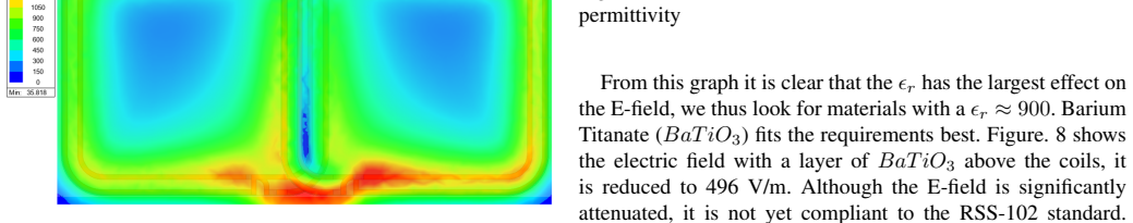
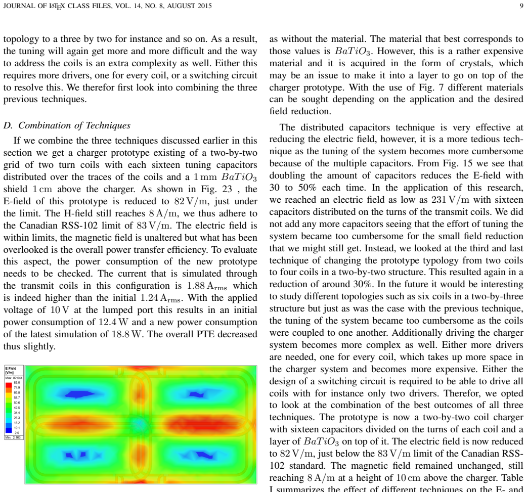
By applying a high-permittivity dielectric shielding layer, distributing the tuning capacitance across sixteen capacitors, and using a two-by-two coil array transmitter, the peak electric field is attenuated from 1416 V/m to 82 V/m at 6.78 MHz. This meets the strictest safety regulation while maintaining the required 8 A/m magnetic field strength and power transfer efficiency. The individual techniques achieve reductions of 65 percent, 84 percent, and 30 percent respectively.
What carries the argument
The three mitigation strategies of dielectric shielding to absorb and redistribute electric fields, distributed resonant tuning capacitors to lower voltage swings, and coil-array transmitter topologies to localize fields.
If this is right
- Dielectric shielding alone reduces the peak E-field by approximately 65 percent to 496 V/m.
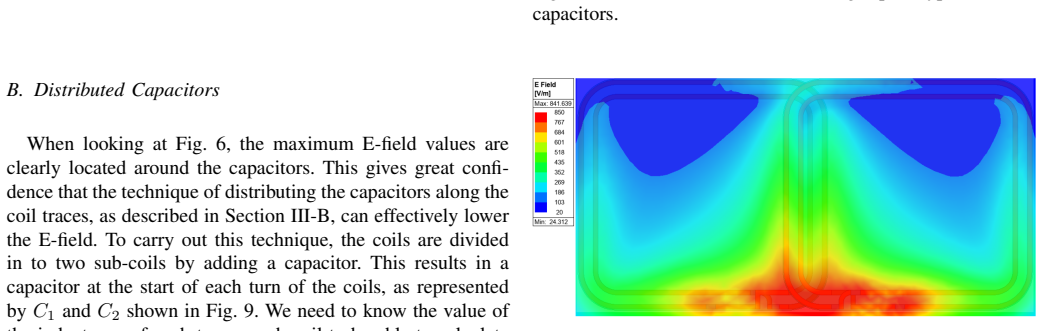
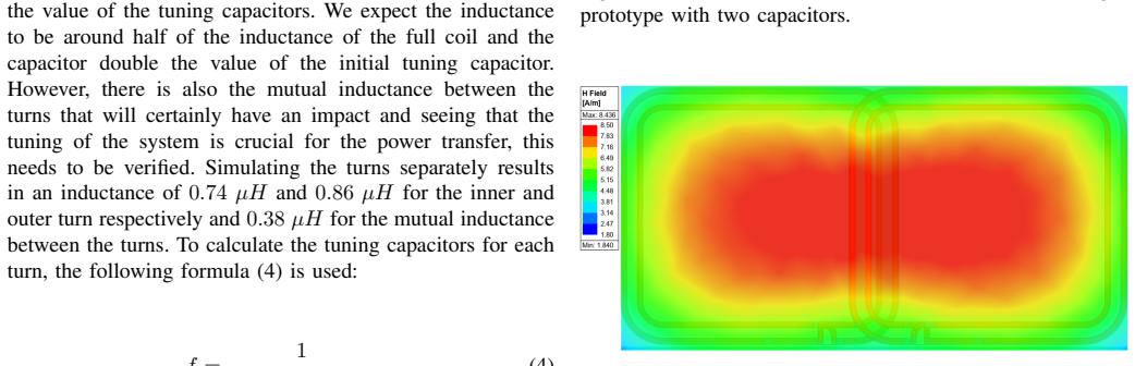
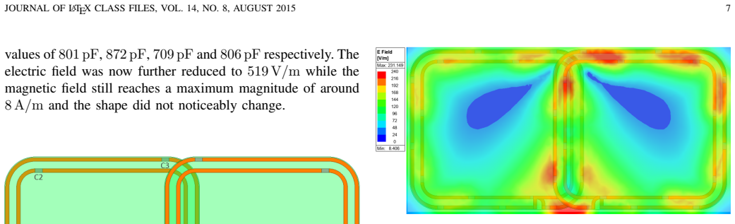
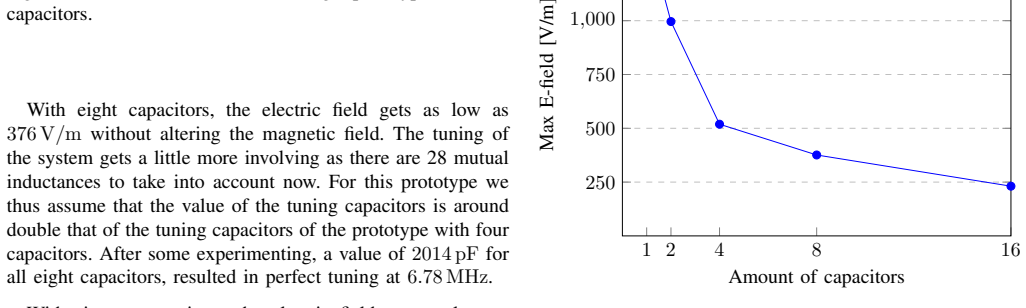
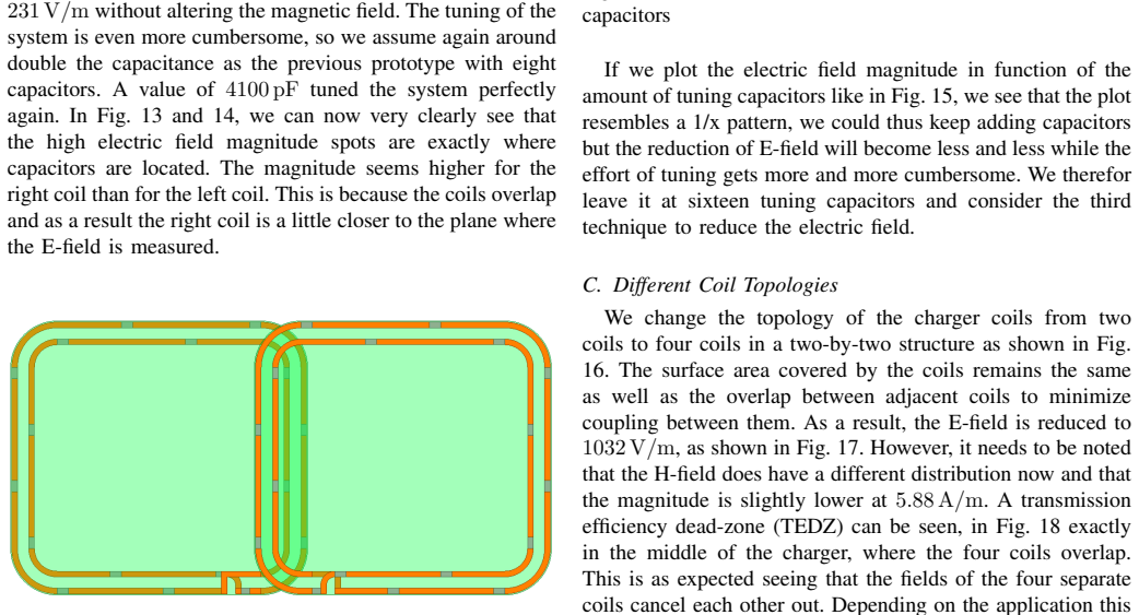
- Distributing the tuning capacitance into sixteen smaller capacitors reduces the peak E-field by approximately 84 percent to 231 V/m.
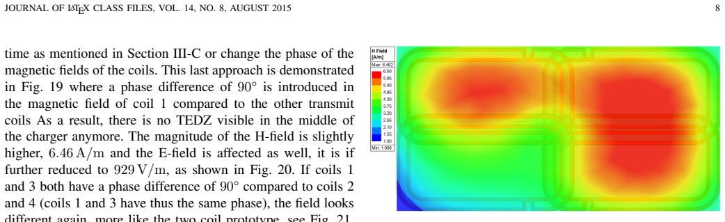
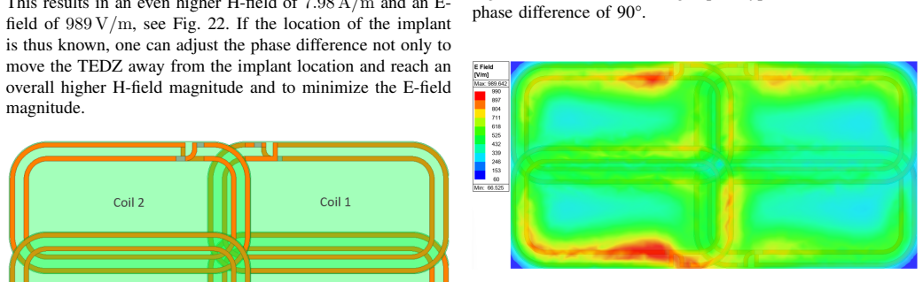
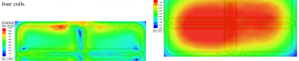
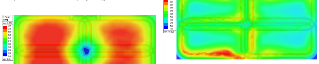
- A two-by-two coil array transmitter reduces the peak E-field by around 30 percent to 990 V/m.
- All three methods together bring the E-field below the 83 V/m limit while the magnetic field and efficiency stay intact.
- Each technique leaves the required magnetic field for power transfer essentially unchanged.
Where Pith is reading between the lines
- The same combination could be tested at other operating frequencies or power levels to see whether the reductions scale.
- Real implants inside living tissue may shift the observed fields enough to require additional margin beyond the modeled 82 V/m result.
- Manufacturers could combine these approaches with existing regulatory test procedures to shorten certification timelines.
- The techniques might extend the usable range beyond 10 cm if the residual E-field budget is used for larger coil separations.
Load-bearing premise
The finite element model accurately predicts real-world E-field and H-field behavior at 6.78 MHz without unmodeled losses, material imperfections, or patient-specific tissue variations.
What would settle it
A bench measurement on a physical prototype using the three techniques together near a tissue-equivalent phantom at 6.78 MHz that records a peak E-field above 83 V/m or a measurable drop in power transfer efficiency.
Figures
read the original abstract
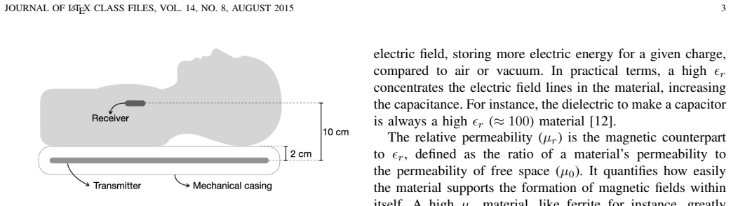
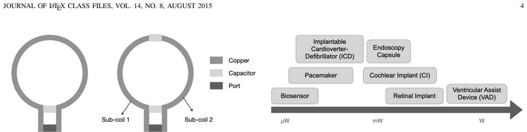
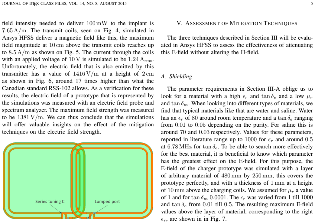
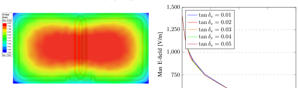
Inductive wireless charging of implantable medical devices necessitates careful control of magnetic and electric field emissions to meet strict safety regulations while delivering sufficient power. When designing a comfortable wireless charger that can operate over distances ranging to 10cm or more, it is difficult not to exceed the most stringent E-field limit of 83~V/m. This paper investigates electric field attenuation techniques for mid-range wireless power transfer at 6.78~MHz. Using \newacronym{fea}{FEA}{finite element analysis}\acrfull{fea} like Ansys \textregistered{} HFSS \texttrademark{}, three mitigation strategies are evaluated; (1) a high-permittivity dielectric shielding layer to absorb and redistribute electric fields, (2) multiple resonant tuning capacitors distributed along the transmitter coil to lower the voltage swing and confine high E-field regions, and (3) alternative coil-array transmitter topologies to spatially localize more confined E-fields. The results show that each technique significantly reduces the E-field magnitude without substantially affecting the H-field. Shielding the transmit coil attenuates the peak E-field from its initial 1416~V/m to 496~V/m, approximately a 65\% reduction. Distributing the tuning capacitance into sixteen smaller capacitors yields a drop from the 1416~V/m to 231~V/m, approximately a 84\% reduction. Both techniques preserve the required 8~A/m magnetic field. The third technique, a two-by-two coil array transmitter reduced the E-field from its 1416~V/m to 990~V/m (around 30\% reduction), though with a slight magnetic field redistribution. All three methods combined, the E-field was successfully attenuated to 82~V/m, just below the strictest limit, without compromising power transfer efficiency. This research demonstrates a feasible approach and framework to safely extend the application of wireless charging for medical implants.
Editorial analysis
A structured set of objections, weighed in public.
Referee Report
Summary. The manuscript uses Ansys HFSS finite-element simulations to evaluate three techniques—high-permittivity dielectric shielding, distributed resonant capacitors along the transmitter coil, and 2x2 coil-array topologies—for attenuating electric-field emissions in 6.78 MHz inductive wireless charging of medical implants. It reports that the individual techniques reduce peak E-field from a 1416 V/m baseline to 496 V/m, 231 V/m, and 990 V/m respectively while preserving an 8 A/m H-field, and that their combination yields 82 V/m (just below the 83 V/m limit) without compromising power-transfer efficiency.
Significance. If experimentally confirmed, the simulation framework could offer a practical route to regulatory-compliant mid-range wireless charging for implants. The work demonstrates that the three techniques can be combined without destroying the required magnetic field, but its significance is constrained by the absence of any physical validation or sensitivity studies.
major comments (2)
- [Abstract] Abstract: The central quantitative claim (combined E-field of 82 V/m, individual reductions to 496/231/990 V/m, baseline 1416 V/m) rests exclusively on unvalidated HFSS FEA outputs. No experimental measurements, prototype data, mesh-convergence study, or sensitivity analysis on tissue permittivity, dielectric loss, or fabrication tolerances are provided, leaving the 1 V/m margin below the 83 V/m limit dependent on untested modeling assumptions.
- [Abstract] Abstract (paragraph on the three mitigation strategies): The assertion that the techniques “preserve the required 8 A/m magnetic field” and “without compromising power transfer efficiency” is stated without reporting how the post-processing extracts these quantities from the HFSS solution or how boundary conditions and material models affect the H-field and efficiency results.
minor comments (2)
- [Abstract] Abstract contains unreplaced LaTeX commands (\newacronym, \acrfull) that should be rendered as plain text in the final manuscript.
- The manuscript should clarify the exact definition of “peak E-field” (e.g., 1 % or 0.1 % contour) and the observation volume used for the reported values.
Simulated Author's Rebuttal
We thank the referee for the constructive comments. We agree that the simulation-only nature of the study requires greater transparency on post-processing and modeling assumptions, and we will revise the manuscript accordingly. The work is intended as a computational exploration of the three techniques rather than a fully validated experimental demonstration.
read point-by-point responses
-
Referee: [Abstract] Abstract: The central quantitative claim (combined E-field of 82 V/m, individual reductions to 496/231/990 V/m, baseline 1416 V/m) rests exclusively on unvalidated HFSS FEA outputs. No experimental measurements, prototype data, mesh-convergence study, or sensitivity analysis on tissue permittivity, dielectric loss, or fabrication tolerances are provided, leaving the 1 V/m margin below the 83 V/m limit dependent on untested modeling assumptions.
Authors: The manuscript is a finite-element simulation study using Ansys HFSS. We will add a mesh-convergence study and sensitivity analyses on tissue permittivity and dielectric loss to the revised version. Experimental measurements and prototype data are not available, as the scope is limited to computational evaluation of the techniques; this will be stated more explicitly as a limitation. revision: partial
-
Referee: [Abstract] Abstract (paragraph on the three mitigation strategies): The assertion that the techniques “preserve the required 8 A/m magnetic field” and “without compromising power transfer efficiency” is stated without reporting how the post-processing extracts these quantities from the HFSS solution or how boundary conditions and material models affect the H-field and efficiency results.
Authors: We will expand the methods section (or add an appendix) in the revised manuscript to detail the post-processing steps for extracting the H-field magnitude and power-transfer efficiency, including the specific boundary conditions, material models, and HFSS solution quantities used. revision: yes
- Absence of experimental measurements or prototype data, as the study consists solely of HFSS finite-element simulations with no physical validation performed.
Circularity Check
No circularity: results are direct simulation outputs with no self-referential derivation
full rationale
The paper evaluates three E-field mitigation techniques exclusively via Ansys HFSS finite-element simulations and reports the resulting peak E-field values (baseline 1416 V/m, individual reductions to 496/231/990 V/m, combined 82 V/m). No equations, fitted parameters, self-citations, or uniqueness theorems are invoked that would reduce any reported quantity to the same inputs by construction. The central claims are therefore simulation outputs rather than derivations that collapse into their own assumptions. This is the normal non-circular case for a simulation study.
Axiom & Free-Parameter Ledger
Reference graph
Works this paper leans on
-
[1]
Accessed: Feb
‘History of the Qi Specifications’, Wireless Power Con- sortium. Accessed: Feb. 16, 2026. [Online]. Available: https://www.wirelesspowerconsortium.com/knowledge-base/qi- specification/history-of-the-qi-specifications/
2026
-
[2]
H. Lee, S. Woo, S. Huh, Y . Jun, S. Ha, K. Choi, J. Jang, S. Baek and S. Ahn, ”Human-Safe Wireless Power Transfer System for Tabletop TV with Hybrid EMF Reduction Methods,”IEEE Wireless Power Technology Conference and ExpoRome, Italy, 2025
2025
-
[3]
T. Cretu, Z. Molseed, J. Gooch, G. Tewolde, and C. Duan, ‘Wireless Qi- charged AGV Navigation and V oltage Sensor Fusion for Coil Alignment- targeted Auto-parking and Foreign Object Detection’,IEEE Wireless Power Technology Conference and Expo(WPTCE), Jun. 2025, pp. 1–5. doi: 10.1109/WPTCE62521.2025.11062275
-
[4]
Accessed: Feb
‘SAE International — Advancing mobility knowledge and solutions’. Accessed: Feb. 16, 2026. [Online]. Available: https://www.sae.org/standards/j2954 202408-wireless-power-transfer- light-duty-plug-electric-vehicles-alignment-methodology
2026
-
[5]
R. Qin, J. Li, J. Sun, and D. Costinett, ‘Shielding Design for High- Frequency Wireless Power Transfer System for EV Charging with Self- Resonant Coils’,IEEE Energy Conversion Congress and Exposition (ECCE), Detroit, MI, USA: IEEE, Oct. 2022, pp. 1–8
2022
-
[6]
S. Woo, Y . Shin, J. Rhee, S. Huh, and S. Ahn, ‘Design of Resonant Circuit Components to Suppress Both EMF and EMI in Wireless Power Transfer Systems for Electric Vehicles’,IEEE Journal of Emerging and Selected Topics in Power Electronics, vol. 13, no. 4, pp. 4358–4368, Aug. 2025
2025
-
[7]
Yang et al., ‘Powering Implantable and Ingestible Electronics’, Advanced Functional Materials, vol
S.Y . Yang et al., ‘Powering Implantable and Ingestible Electronics’, Advanced Functional Materials, vol. 31, no. 44, p. 2009289, Oct. 2021
2021
-
[8]
ETSI, EN300330 v2.1.1”Short Range Devices (SRD); Radio equipment in the frequency range 9 kHz to 25 MHz and inductive loop systems in the frequency range 9 kHz to 30 MHz; Harmonised Standard covering the essential requirements of article 3.2 of Directive 2014/53/EU”(2017)
2014
-
[9]
Innovation, Science and Economic Development Canada (ISED),RSS- 102, Issue 6: Radio Frequency (RF) Exposure Compliance of Radiocom- munication Apparatus (All Frequency Bands),(2023)
2023
-
[10]
J. Ahn et al., ‘An Out-of-Phase Wireless Power Transfer System for Implantable Medical Devices to Reduce Human Exposure to Electromag- netic Field and Increase Power Transfer Efficiency’,IEEE Transactions on Biomedical Circuits and Systems, vol. 16, no. 6, pp. 1166–1180, Dec. 2022
2022
-
[11]
S. Das, D. Mitra, A. S. Chezhian, B. Mandal, and R. Augustine, ‘A novel SAR reduction technique for implantable antenna using conformal absorber metasurface’, Front Med Technol, vol. 4, p. 924433, Aug. 2022
2022
-
[12]
M. T. Sebastian,Dielectric Materials for Wireless Communication Elsevier, 2008
2008
-
[13]
Kabiri, L
A. Kabiri, L. Yousefi, and O. M. Ramahi, ‘Magnetic loss tangent optimization in design of artificial magnetic slabs’,IEEE Antennas and Propagation Society International Symposium, Jul. 2008, pp. 1–4
2008
-
[14]
L. F. Chen, C. K. Ong, C. P. Neo, V . V . Varadan, and V . K. Varadan, Microwave Electronics: Measurement and Materials Characterization, 1st edn. Wiley, 2004
2004
-
[15]
Nezaratizadeh, S
A. Nezaratizadeh, S. Mahmud and A. Khalifa, ”Coils Parallelization: A Strategy for Improving Power Transfer Efficiency and Specific Absorp- tion Rate in Wireless Power Transfer System for Implantable Medical Devices,”WPTCE2024, 2024. [16]Ansys HFSS, version 2024 R2, ANSYS Inc
2024
-
[16]
K. Bocan and E. Sejdi ´c, ”Adaptive Transcutaneous Power Transfer to Implantable Devices: A State of the Art Review,”Sensors, vol. 16, issue 3, p. 393, Mar. 2016, doi: 10.3390/s16030393
-
[17]
Van Mulders, D
J. Van Mulders, D. Delabie, C. Lecluyse, C. Buyle, G. Callebaut, L. Van der Perre, and L. De Strycker, ”Wireless Power Transfer: Systems, Circuits, Standards, and Use Cases,”Sensors, vol. 22, issue 15, pp. 5573, 2022
2022
-
[18]
Van Mulders, S
J. Van Mulders, S. Boeckx, J. Cappelle, L. Van der Perre and L. De Strycker, ”UA V-based solution for extending the lifetime of IoT devices: Efficiency, Design and Sustainability,”Frontiers, 2023
2023
-
[19]
Fleisch,A Student’s Guide to Maxwell Equations,New York, United States of America: Cambridge University Press, 2008
D. Fleisch,A Student’s Guide to Maxwell Equations,New York, United States of America: Cambridge University Press, 2008
2008
discussion (0)
Sign in with ORCID, Apple, or X to comment. Anyone can read and Pith papers without signing in.