REVIEW 2 major objections 6 minor 36 references
Polaris: a flexible stellarator demonstration experiment with simple modular coils
T0 review · 2 major / 6 minor · reviewed 2026-08-01 · deepseek-v4-flash
Pith's one-line read Polaris demonstrates that six identical, circular, water-cooled coils—optimized only in position and tilt—can generate a sizable volume of closed magnetic surfaces with rotational transform near 0.3 and confine a low-temperature plasma for
desk verdict A well-executed proof-of-principle for simple-coil stellarators, with honest first plasma results; the as-built magnetic topology isn't directly verified, but the paper doesn't oversell it. read the letter →
The pith
A machine-rendered reading of the paper's core claim, the machinery that carries it, and where it could break.
The reading
What carries the argument
The enabling design element is the optimized arrangement of six identical circular coils (25 cm diameter, 16 turns each) inside a vessel, leaving 5 free degrees of freedom under 3-fold periodicity and stellarator symmetry. The coils are first optimized as filaments and then evaluated as finite-width bundles; the rotational transform is produced by the torsion of the magnetic axis rather than by coil helicity. A second load-bearing component is the all-glass vacuum vessel, which gives 360-degree optical access and fast interchange of coil sets via replaceable base plates; the in-vessel RF antenna with a Faraday shield and ceramic casing ignites the plasma inductively.
What would settle it
Measure the actual coil positions (for example by photogrammetry or coordinate measurement) and map the vacuum magnetic surfaces directly (for example with an electron beam or fluorescent rod). If any coil is displaced more than about 1 cm, or if the measured last closed surface shows the 1/3 island chain predicted for that displacement, the claimed robustness and the interpretation of 'confinement' as magnetic-surface confinement would need revision.
Extended reading notes
Core claim
The paper's central claim is that a stellarator with substantial rotational transform and practical error tolerance can be built from six identical planar circular coils, positioned and tilted by single-stage optimization. Rotational transform arises from the integrated torsion of the magnetic axis, not from coil helicity: iota approximately equals (1/2pi) times the line integral of torsion minus N. Numerically, the configuration yields 0.05 cubic meters of closed vacuum flux surfaces with 0.27 < iota < 0.31, and surfaces survive random coil displacements below 1 centimeter. Experimentally, the plasma glow tracks the computed last closed surface, densities and temperatures are typical of a c
Load-bearing premise
The whole confinement story rests on the as-built coils matching the optimized geometry within the about-1-cm tolerance, but the paper does not report coil metrology or direct magnetic-surface mapping—only a single on-axis field measurement and the apparent match of the luminous plasma to the computed boundary.
Editorial extensions
If this is right
- Simple identical circular coils can serve as a proof-of-principle for low-complexity stellarator optimization, potentially reducing coil manufacturing costs.
- A 1-cm coil positioning tolerance, several percent of the major radius, is much looser than typical optimized stellarator designs and simplifies assembly.
- The measured two-phase plasma decay after RF turn-off separates radiation losses (fast, about 30 microseconds) from cross-field transport (slow, about 1 millisecond) in this collisional regime.
- Rotating one coil by 180 degrees degrades the global confinement time by about 30 percent, showing the optimized field measurably improves confinement even in a low-temperature, neutral-dominated plasma.
- Polaris provides a platform for studying drift or interchange instabilities and neutral-dominated edge physics in a three-dimensional magnetic geometry.
Reading between the lines
- If the centimeter-scale tolerance extrapolates to larger devices, simple-coil stellarators might be built without the precision metrology typical of big optimized machines; a natural test is deliberately scanning coil displacement past 1 cm and mapping the resulting island widths.
- The optical transparency invites direct validation of field-line tracing: a fluorescent rod inserted along predicted surfaces, as the paper suggests, would confirm the nested-surface picture that currently rests on one on-axis field reading and the plasma glow.
- The 109 kHz fluctuation, once its poloidal wavenumber is measured, could be used to test whether drift or interchange scaling laws hold in a stellarator edge analog, giving low-cost data for turbulence transport models.
- Because the vessel permits rapid coil swaps, Polaris could systematically scan the simple-coil configuration space—varying tilt angles and positions—to produce an empirical map of which nearby arrangements confine best, complementing numerical optimization.
Signed reviews
Editorial analysis
A structured set of objections, weighed in public.
Referee Report
Summary. The paper describes the design, construction, and first plasma experiments of Polaris, a small stellarator at the Swiss Plasma Center with six identical circular modular coils arranged inside a glass vacuum vessel. The coil geometry was obtained by single-stage optimization with SIMSOPT (Ref. 17), giving vacuum magnetic surfaces with rotational transform 0.27<iota<0.31 over about 0.05 m^3 and a nominal robustness to coil displacements below 1 cm. The device uses a 13.56 MHz ICP antenna for plasma production, water-cooled copper coils, and full optical access. First plasmas in argon, neon, and helium are reported, with n_e~1e16-1e17 m^-3, T_e~2-6 eV, a dominant 109 kHz fluctuation, and a two-timescale decay of ion saturation current after RF switch-off, with the slow time tau2 about 1.17 ms at 5e-3 mbar. A perturbation experiment, in which one coil is rotated by 180 degrees, shows a ~30% reduction of tau2 and changes in density profiles, interpreted as evidence that the optimized configuration contributes to confinement.
Significance. If the claims are sustained, Polaris is a valuable new university-scale stellarator testbed. Its key strengths are the demonstration of a very simple modular coil set (six identical circular coils) producing substantial rotational transform, a large glass vacuum vessel with full optical access, a flexible coil-inside-vessel concept that allows rapid configuration changes, and a first set of plasma diagnostics including imaging, Langmuir probe profiles, fluctuation spectra, and a coil-perturbation study. The use of standard computational tools (SIMSOPT, VMEC, booz_xform) and the FEA validation of window deformations are positive features. The main limitation is that the experimental verification of the vacuum magnetic topology is indirect, as the as-built coil positions are not measured and no magnetic surface mapping is performed. This limits the strength of the claim that the plasma is confined by the optimized closed flux surfaces rather than by mirror/antenna effects.
major comments (2)
- [IV.A, IV.B, V] The central experimental claim—that the plasma bulk is confined by the optimized closed flux surfaces with rotational transform—is not directly verified. The only quantitative magnetic check is the on-axis field B0 ~ IB/1.25 = 120 G at the coil center (Sec. IV.B), which depends mainly on coil radius and current and is insensitive to the five optimized degrees of freedom. The visible match of the luminous plasma to the computed last closed surface (Sec. IV.A) is suggestive but, in a low-temperature, high-neutral-pressure plasma with Bmax/Bmin ~ 10 (Sec. II), a mirror-dominated discharge can also fill the torus and follow the field shape. The perturbation experiment (Sec. IV.E) shows that even with coil 2A rotated 180 degrees the plasma still fills the torus and tau2 is reduced by only about 30%, so toroidal propagation and slow decay do not by themselves imply closed flux surfaces. Sectio
- [IV.C] The 'global confinement time' tau2 is inferred from a two-exponential fit to the ion-saturation decay at a single probe position (r=0, toroidal location 5b). Because n_e varies by 60-75% between toroidal locations 4e and 5b (Fig. 15) and the mirror ratio is large, a local decay time need not equal the global particle or energy confinement time; it could reflect local parallel redistribution or losses. In addition, the attribution of tau1 to electron-neutral radiative losses is plausible but is not directly supported by time-resolved Te or radiation measurements. Please rename this quantity a 'local ion-saturation decay time' and, if the global statement is retained, support it with measurements at several toroidal/poloidal positions or with a model that accounts for the mirror geometry.
minor comments (6)
- [II, Fig. 4] The text says surfaces are 'well preserved for perturbations up to delta_x < 1 cm', but the delta_x = 1 cm case in Fig. 4 shows a clear 1/3 island. Define the quantitative criterion for 'well preserved' (e.g., island width, fraction of destroyed flux, or maximum acceptable deviation) and clarify that the bound is strict.
- [IV.B, Fig. 13] The mean n_e and T_e profiles in Fig. 13 are shown without error bars. Since the fluctuations of V_f are reported with standard deviations, it would be helpful to also give shot-to-shot or statistical uncertainties for n_e and T_e, especially because the inset claims a linear dependence on ionization energy.
- [IV.D, Fig. 15] The caption of Fig. 15 says 'toroidal location 4e and 4b', while the text refers to 4e and 5b. Also, the text describes the modified-configuration profiles as 'purple curves' while the caption says 'black curves'; please reconcile.
- [IV.E] In the confinement-time paragraph, the low pressure is given as 0.15e-3 mbar, which appears to be a typo for 1.5e-3 mbar. Please correct.
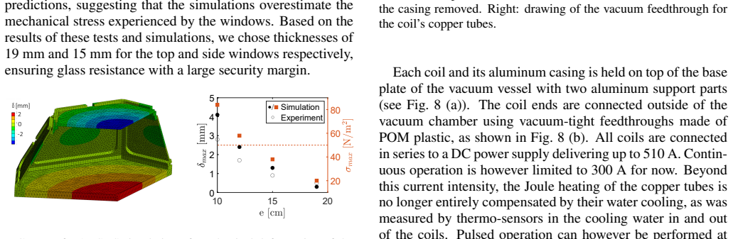
- [III.A/III.B] The engineering sections are informative, but a few statements would benefit from clarification: the 'total current in each coil' in the abstract (~5 kA) should be explicitly defined as ampere-turns (16 turns times coil current), and the window deformation test results (experimental values ~30% lower than simulated) should be reported with uncertainties.
- [Data Availability] For a device paper, consider making the optimized coil geometry and the raw plasma profiles available in a public repository, rather than only 'upon reasonable request', to improve reproducibility.
Circularity Check
No significant circularity: the rotational transform is an explicit optimization target, not an independent prediction; experimental checks are external to the design.
full rationale
The paper's central design property, the rotational transform 0.27<iota<0.31, is not presented as a prediction derived from independent inputs. Section II states explicitly that the coil positions and orientations 'were optimized to produce a given volume of vacuum magnetic surfaces and with a given target rotational transform.' The later statement that the volume is about 0.05 m3 and the rotational transform is 0.27<iota<0.31 is a report that the optimization target was met, not a fitted parameter disguised as a discovery. The experimental evidence is external to the optimization: the measured on-axis field B0 ~ I_B/1.25 = 120 G is checked against the theoretical expression B0 ~ mu0 N I_B/(2 r0) from Section III.D, and the plasma shape is compared visually with the computed last closed surface. These are independent checks, not quantities used to construct the coil configuration. The reliance on Ref. 17 for the guided coil optimization method is a self-citation lineage (Jorge, Giuliani, and Loizu overlap with the present authors), but the optimization is re-executed here with SIMSOPT and analyzed with VMEC, so the result is not merely an assertion imported from the prior paper. No uniqueness theorem or ansatz is smuggled in via citation; Ref. 17 provides a method, not a forced conclusion. The perturbation experiment (coil 2A rotated 180 degrees) provides a measured 30% reduction in tau2, an actual experimental contrast rather than a circular prediction. The paper's own stated limitation, that fluorescent-rod magnetic-surface mapping is future work (Section V), is a validation gap for the as-built coil geometry, not equation-level circularity. Overall, no load-bearing step reduces to its own input by construction.
Assumptions & free parameters
free parameters (1)
- Positions/orientations of the six identical circular coils (5 degrees of freedom) =
Not disclosed in the paper (optimized by SIMSOPT)
assumptions (6)
- domain assumption Six identical circular coils optimized by the guided coil optimization method of Ref. 17 (single-stage optimization with SIMSOPT) produce the computed vacuum field with the stated ι and volume.
- standard math Field-line tracing, VMEC, and booz_xform correctly compute magnetic surfaces and Boozer coordinates for the vacuum field.
- domain assumption The double Langmuir probe I-V interpretation yields accurate n_e and T_e at B≈120 G, n_e≈10¹⁶–10¹⁷ m⁻³, and RF heating at 13.56 MHz.
- domain assumption The visible plasma emission traces the computed last closed magnetic surface, so the plasma shape is evidence of magnetic confinement.
- domain assumption The two-exponential decay of the local ion-saturation current after RF switch-off reflects a radiation-dominated fast phase and a global cross-field transport time τ2.
- standard math The on-axis rotational transform can be estimated from the integrated torsion of the magnetic axis, ι=(1/2π)∫τ dl − N as in Ref. 19.
Cite this review
Pith. "Pith review of Polaris: a flexible stellarator demonstration experiment with simple modular coils." pith.science (2026). https://pith.science/paper/TWEMX3OL
@misc{pith2026260725409,
  author       = {Pith},
  title        = {Pith review of: Polaris: a flexible stellarator demonstration experiment with simple modular coils},
  year         = {2026},
  howpublished = {\url{https://pith.science/paper/TWEMX3OL}},
  note         = {Machine review of arXiv:2607.25409}
}
read the original abstract
We present the design, construction, and first plasma experiments of Polaris, a new small-scale stellarator experiment (major radius R ~ 0.4 m) located at the Swiss Plasma Center. Polaris consists of a relatively large vacuum vessel (~0.5 m^3) predominantly made of glass windows and inside which different sets of magnetic coils can be installed. A first modular coil configuration has been designed with six identical, circular, water-cooled copper coils toroidally arranged in an optimal way so that they generate a large volume of magnetic surfaces and rotational transform in vacuum (iota ~ 0.3). The total current in each coil goes up to ~ 5 kA, producing a magnetic field on-axis of B ~ 0.03 T. An RF antenna specifically designed to operate in vacuum delivers up to 2.5 kW of power to produce plasma via inductive coupling and electron-impact ionization. We present the engineering solutions adopted for the design of Polaris and illustrate the great experimental flexibility it enables. Time-averaged values and fluctuations of plasma density, electron temperature, and floating potential are measured at various toroidal locations, providing insights into the plasma equilibrium, electrostatic turbulence, and associated transport. The glass vacuum chamber of Polaris additionally provides unprecedented optical access to the entire plasma volume. With its original, flexible design, Polaris is a 'stellarator fish-tank', allowing interchangeable coil sets and exploration of various magnetic configurations. Furthermore, its low-temperature, low-density, high-neutral-pressure plasmas are relevant to stellarator edge physics, making Polaris a first-of-kind testbed for the fundamental investigation of stellarator edge-relevant physics.
Figures


Figures from the paper (12 more)




Reference graph
Works this paper leans on
-
[1]
M. A. Lieberman and A. J. Lichtenberg , title =
-
[2]
Chabert and N
P. Chabert and N. Braithewaite. Physics of radio-frequency plasmas
-
[3]
S. P. H. Vincent , title =
-
[4]
B. N. Rogers and J. F. Drake and A. Zeiler , journal =. Phase Space of Tokamak Edge Turbulence, the
-
[5]
Plasma Phys
Ballooning stability optimization of low-aspect-ratio stellarators , author =. Plasma Phys. Control. Fusion , volume =
-
[6]
Krause and C
N. Krause and C. Lechte and J. Stöber and U. Stroth and E. Ascasibar and J. Alonso and S. Niedner , volume =. The. Rev. Sci. Instrum. , year =
-
[7]
T. S. Pedersen and A. H. Boozer and J. P. Kremer and R. G. Lefrancois and W. T. Reiersen and F. Dahlgren and N. Pomphrey. The Columbia Nonneutral Torus : a new experiment to confine nonneutral and positron-electron plasmas in a stellarator. Fusion Sci. Technol. 2004
2004
-
[8]
Rypdal and S
K. Rypdal and S. Ratynskaia. Onset of Turbulence and Profile Resilience in the Helimak Configuration. Phys. Rev. Lett. 2005
2005
Show all 36 references
-
[9]
Fasoli and B
A. Fasoli and B. Labit and M. McGrath and S. H. Müller and G. Plyushchev and M. Podestà and F. M. Poli. Electrostatic turbulence and transport in a simple magnetized plasma. Phys. Plasmas. 2006
2006
-
[10]
Theory of plasma confinement in non-axisymmetric magnetic fields , volume =. Rep. Prog. Phys. , author =. 2014 , pages =
2014
-
[11]
Andruczy and D.N
D. Andruczy and D.N. Ruzic and D. Curreli and J.P. Allain and the HIDRA Team. HIDRA : Hybrid Illinois device for research and applications. Fusion Sci. Technol. 2015
2015
-
[12]
V. I. Vargas and J. Mora and C. Otarola and E. Zamora and J. Asenjo and A. Mora and E. Villalobos , year =. Implementation of stellarator of. 2015
2015
-
[13]
Fusion Eng
From. Fusion Eng. Des. , author =. 2017 , pages =
2017
-
[14]
2021 , pages =
JOSS , author =. 2021 , pages =
2021
-
[15]
Vincent and V
S. Vincent and V. Dolique and N. Plihon. High-speed imaging of magnetized plasmas : When electron temperature matters. Phys. Plasmas. 2022
2022
-
[16]
T. M. Qian and X. Chu and C. Pagano and D. Patch and M. C. Zarnstorff and B. Berlinger and D. Bishop and A. Chambliss and M. Haque and D. Seidita and C. Zhu. Design and construction of the. J. Plasma Phys. 2023
2023
-
[17]
Jorge and A
R. Jorge and A. Giuliani and J. Loizu. Simplified and flexible coils for stellarators using single stage optimization. Phys. Plasmas. 2024
2024
-
[18]
Sepulchre and S
C. Sepulchre and S. P. H. Vincent and P. Quigley and M. Baquero-Ruiz and I. Furno. Impact of the magnetic shear on plasma equilibrium and turbulent transport in the vicinity of an X-point in TORPEX. Phys. Plasmas. 2025
2025
-
[19]
Fusion Eng
Stellaris:. Fusion Eng. Des. , author =. 2025 , pages =
2025
-
[20]
Plasma Phys
Back to the figure-8 stellarator , volume =. Plasma Phys. Control. Fusion , author =. 2025 , pages =
2025
-
[21]
The. J. Plasma Phys. , author =. 2025 , pages =
2025
-
[22]
and Velasco, J
Sánchez, E. and Velasco, J. L. and Calvo, I. and García-Regaña, J. M. and Salcuni, C. and Alonso, J. A. , journal =. 2026 , volume =
2026
-
[23]
arxiv , author =
Overview of the. arxiv , author =
-
[24]
Landreman and R
M. Landreman and R. Jorge , journal =. Magnetic well and
-
[25]
O. E. Garcia and J. Horacek and R. A. Pitts and A. H. Nielsen and W. Fundamenski and J. P. Graves and and V. Naulin and J. Juul Rasmussen , journal =. Interchange turbulence in the
-
[26]
L. E. Dudek and J. H. Chrzanowski and P. J. Heitzenroeder and S. Raftopoulos and M. E. Viola and G. H. Neilson and D. Rej and M. J. Cole and P. Goranson and K. Freudenberg , journal =. Status of the
-
[27]
Klinger and C
T. Klinger and C. Baylard and C. D. Beidler and J. Boscary and H. S. Bosch and A. Dinklage and D. Hartmann and P. Helander and H. Ma. Towards assembly completion and preparation of experimental campaigns of. Fusion Eng. Des. , volume =
-
[28]
Killer and Y
C. Killer and Y. Narbutt and O. Grulke and the W-7 Team , journal =. Turbulent transport in the scrape-off layer of
-
[29]
The physics of turbulence localised to the tokamak divertor volume , author =. Commun. Phys. , volume =
-
[30]
PRX Energy , volume =
Quasi-Isodynamic Stellarators with Low Turbulence as Fusion Reactor Candidates , author =. PRX Energy , volume =
-
[31]
A quasi-isodynamic stellarator configuration towards a fusion power plan , author =. J. Plasma Phys. , volume =
-
[32]
and Acton, G
Grulke, O. and Acton, G. and Adamek, J. and Aggelis, D. and Alamo-Calderon, R.-M. and Albert, C. and Aleynikov, P. and Aleynikova, K. and Alonso, A. and G. C. Amanekwe. Overview of. Nucl. Fusion , volume =
-
[33]
Liu and H
X. Liu and H. Liu and Y. Cao and Y. Xu and J. Zhang and A. Shimizu and M. Shoji and M. Isobe and J. Cheng and X. Wang and J. Huang and H. Liu and X. Zhang and J. Shen and J. Hu and Y. Li and W. Xuan and C. Tang , journal =. Influence of stochastic coil perturbations on magneti...
-
[34]
Steepest-descent moment method for three-dimensional magnetohydrodynamic equilibria , author =. Phys. Fluids , volume =
-
[35]
R. C. Wolf and Ali, A. and Alonso, A. and Baldzuhn, J. and Beidler, C. and Beurskens, M. and Biedermann, C. and Bosch, H.-S. and Bozhenkov, S. and R. Brakel. Major results from the first plasma campaign of the. Nucl. Fusion , year =
-
[36]
Nature , author =
Demonstration of reduced neoclassical energy transport in. Nature , author =. 2021 , pages =
2021
Reviewed August 1, 2026 · model on record in the stance chip above.
Discussion (0). Continue with ORCID to comment.