REVIEW 2 major objections 5 minor 37 references
Near-Field Communications with Grating Lobes for Quasi-Distributed Arrays: From ULA to MRA
T0 review · 2 major / 5 minor · reviewed 2026-08-03 · deepseek-v4-flash
Pith's one-line read Modular near-field arrays create grating lobes in the distance domain as well as the angle domain, and spacing antennas nonuniformly inside each module suppresses both without adding antennas.
desk verdict Distance-domain grating lobes in modular near-field arrays are a genuinely new result, and the M-MRA is a plausible antenna-efficient fix; the paper is worth refereeing, but it has a factor-of-ten slip in Eq. (34) and an unexamined per-module far-field assumption where the MRA aperture is sizable. read the letter →
The pith
A machine-rendered reading of the paper's core claim, the machinery that carries it, and where it could break.
The reading
What carries the argument
The key mechanism is the envelope/array-factor decomposition of the near-field beam pattern: the total gain factors into a slowly varying intra-module envelope C_l (a sinc-like function of the per-antenna offsets) and a rapidly varying inter-module array factor G_L determined by the module-center positions. Grating-lobe locations come from the in-phase conditions of G_L—for even L the quadratic phase coefficient must be an integer multiple of π, for odd L both even and odd multiples—while the envelope's main-lobe width decides whether those lobes have meaningful power. The proposed M-MRA exploits this by replacing each uniform subarray with a minimum-redundancy array, whose nonuniform spacin
What would settle it
Compute the exact near-field beam pattern of an M-MRA with N=10, L=4, d_s=1 m at 15 GHz and a user at r=20 m without dropping the intra-module quadratic phase term e^{jκ y_n² φ/2}; if distance-domain grating-lobe peaks reappear at the heights predicted by the M-ULA formulas, or if the simulated spectral-efficiency gain over M-ULA falls well below the reported ~80%, the paper's central claim fails.
Extended reading notes
Core claim
The central claim is that near-field grating lobes of modular arrays live in two dimensions: angle and distance. For an M-ULA with an even number of modules L, the lobe positions are sinθ_n = sinθ_F + nλ/d_s and r_m = r_F d_s² cos²θ / (d_s² cos²θ_F − mλ r_F), with analogous formulas for odd L that interleave the distance lobes at half-integer angle offsets. The beam pattern separates into a rapidly varying array factor set by module spacing and a slowly varying envelope set by the intra-module layout; the envelope decides whether a potential lobe is actually strong. The paper argues that increasing antennas per module narrows the envelope but requires N to scale linearly with module spacing.
Load-bearing premise
The load-bearing premise is that each module is small enough for users to be in its far field, so the quadratic phase variation inside a module can be dropped; if users sit inside a module's near field, the envelope/array-factor separation and the M-MRA suppression argument no longer hold.
Editorial extensions
If this is right
- Near-field grating lobes must be treated as angle-distance phenomena: users separated only in distance can still interfere if their positions coincide with a distance-domain lobe.
- Design rules for modular arrays change: inter-module spacing should be chosen near an inflection point, not maximized, and the required antennas per module grows linearly with spacing for M-ULA.
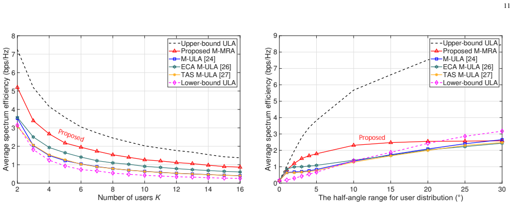
- M-MRA reaches comparable multi-user spectral efficiency to an M-ULA with about one-third the antennas in the simulated setup (N=8 vs N=24).
- The suppression works best when users lie within a limited angular spread; outside roughly a 30-degree half-angle range, M-MRA's higher sidelobes erase the gain.
- High-SNR near-field systems are interference-limited, so structural grating-lobe suppression matters more than raising transmit power.
Reading between the lines
- A testable extension is to let users sit at two distances along the same angle and deliberately place one at a distance-domain grating lobe of the other; the closed-form lobe formulas predict exactly where interference peaks, which could turn lobe locations into a scheduling resource.
- The analysis assumes each module is in the far field of its own aperture; for M-MRA modules with apertures near 0.5 m, users at 20 m can lie inside the module near field, so the suppression gain may be distance-dependent and should be validated with the full quadratic phase included.
- The same minimum-redundancy idea should transfer to planar modular arrays by applying low-redundancy placement along both axes, which the paper lists as future work; the distance-domain lobe pattern would then become a set of rings/points in 3D.
- Because MRA sidelobes are higher, the M-MRA gain is sensitive to the angular spread of users; a hybrid design that switches module layout by scenario, or applies digital windowing per module, would preserve the narrow envelope without the sidelobe penalty.
Editorial analysis
A structured set of objections, weighed in public.
Referee Report
Summary. The paper analyzes near-field beam patterns for modular linear arrays (M-ULA) and proposes a modular minimum-redundancy array (M-MRA) to suppress grating lobes. It derives closed-form grating-lobe locations for even and odd numbers of modules (Lemmas 1 and 2), obtains beamwidth and beamdepth expressions, derives a condition on the number of antennas per module to avoid grating lobes for M-ULA, and then argues that replacing each ULA module by an MRA narrows the spatial envelope in both angle and distance, thereby suppressing grating lobes without adding antennas. Simulations compare M-ULA, M-MRA, ECA, TAS, and collocated ULA benchmarks in terms of multi-user spectrum efficiency.
Significance. If the main claim holds, the paper offers a hardware-level, antenna-efficient solution to grating-lobe interference in quasi-distributed arrays, with useful closed-form design formulas. The derivations are parameter-free from the MRT/Fresnel model, and the comparison against ECA/TAS is a useful practical benchmark. However, the central quantitative design rule in Section IV-A contains an internal arithmetic inconsistency, and the analytical mechanism for M-MRA relies on a per-module far-field approximation that is violated in the simulated parameter regime. These issues need to be resolved before the contribution is fully established.
major comments (2)
- [§IV-A, Eqs. (32)–(34)] There is an internal inconsistency in the derivation of the single-region beamfocusing condition. With BW_enve = 1.772/N and sinθ1 = λ/d_s, the condition sinθ1 ≥ BW_enve gives λ/d_s ≥ 1.772/N. Substituting d_s = d_z + (N−1)d and d = λ/2 yields N ≥ 7.77(d_z/d − 1), not N ≥ 0.795(d_z/d − 1) as printed. The printed constant is smaller by a factor of roughly 9.8. This matters because the numerical example in Fig. 6 (N=160, d_z=2 m) does not satisfy the corrected condition, so either the condition, the beamwidth definition, or the simulation conclusion needs reconciliation. Please correct the algebra and state explicitly whether 'single-region' is defined by the 3-dB envelope or by some other threshold.
- [§III-A/§IV-B, Eqs. (9)–(10), Figs. 8–11] The M-MRA suppression mechanism relies on the same envelope/array-factor decomposition as M-ULA, which neglects the intra-module quadratic phase e^{jκ y_n^2 φ/2} in Eq. (9). The justification given for M-ULA (N=25, per-module Rayleigh distance ≈6.25 m) does not carry over to M-MRA: an N=10 MRA has aperture on the order of 50d = 0.5 m at 15 GHz, giving a per-module Rayleigh distance of about 25 m. The simulated users at r = 20–30 m in Section V-A therefore lie inside each module's near field, and the dropped phase is not negligible (e.g., ~0.2–0.3 rad at the first distance-domain grating lobe for r=20 m). Moreover, the cited MRA configurations are not symmetric, so C_l is generally complex; its phase enters the outer summation and can shift the grating-lobe condition, invalidating the two-step decoupling. The paper does not state whether the simulations use the exact spherical model or th
minor comments (5)
- [§III-B, Lemma 1 proof] The sentence 'l(l+1) is always even when L is even' is imprecise: l(l+1) is always even for any integer l. The intended argument still works, but the wording should be corrected.
- [§IV-B, Fig. 8] Please list or explicitly cite the exact MRA antenna positions used for N=10. The envelope comparison in Fig. 8 and the beamwidth ratio in Fig. 7(b) depend on the specific MRA configuration, and different MRA layouts can have different sidelobe levels.
- [§IV-A, Eq. (33)] The condition sinθ1 ≥ BW_enve compares a grating-lobe location to the full 3-dB beamwidth, but the derivation of Eq. (34) appears to use a different numerical constant. Please ensure the beamwidth definition (full width vs. half width) is consistent throughout the section.
- [§V-B, Figs. 11–12] The figure legends contain a typo ('Propo sed' instead of 'Proposed'). Also, consider reporting the per-user SINR or a fairness metric, since average spectrum efficiency can mask large differences in user experience.
- [General] The statement in Section III-A that the intra-module quadratic phase is negligible is justified for the M-ULA example but is later applied to M-MRA without restating the validity condition. A short quantitative validity condition (e.g., r > 2D_sub^2/λ) would help the reader assess the regime of the analytical results.
Circularity Check
No significant circularity: grating-lobe locations and M-MRA suppression follow from parameter-free algebra on the stated near-field steering-vector model, with MRA apertures cited from external 1968/1993 literature; the only caveat (per-module far-field approximation) is a regime-validity concern, not an input-output equivalence.
full rationale
The paper's central results are derived by parameter-free manipulation of the stated model. Eq. (8) is the squared inner product of two near-field steering vectors under the Fresnel approximation; Eqs. (14)-(17) introduce the linear phase coefficient β and quadratic phase coefficient α and solve the peak conditions of the inter-module array factor exactly, yielding Eq. (12) and Eqs. (18)-(19) with no fitted constant. The grating-lobe locations are then used to derive the ULA suppression condition (33)-(34) by comparing the first lobe position with the envelope's computed half-power beamwidth (32); again no parameter is fitted. The M-MRA advantage is not derived by assuming the conclusion: the narrow-envelope property used is the external, well-known aperture property of minimum-redundancy arrays from Moffet (1968) and Ruf (1993), not the authors' own prior work; the paper only transfers that aperture property into the envelope factor C_l of Eq. (10). The ~80% SE improvement is produced by the simulation in Sec. V, which uses the Fresnel channel model of Eq. (3) that retains the intra-module quadratic phase; the simulation is therefore not constrained to the same approximation used in the analytical envelope decomposition, and no parameter was fit to make Fig. 11 match the analysis. Self-citations [13], [30], [31] are background, channel-model, and Taylor-expansion citations; none is load-bearing and none forbids alternatives. The one flagged limitation is the drop of e^{jκy_n^2 φ/2} in Eq. (9), justified by a small per-module aperture; for M-MRA with N=10 and users at 20-30 m, the per-module Rayleigh distance can be ~25 m, so this stated validity condition may be violated in the simulated regime. That is a regime/accuracy concern about the explanatory mechanism in Sec. IV-B, not an instance where a prediction reduces to its input by construction; hence it does not raise the circularity score.
Assumptions & free parameters
assumptions (5)
- domain assumption Fresnel approximation: r_{k,l,n} ≈ r_k − y_{l,n} sinθ_k + y_{l,n}² cos²θ_k/(2r_k)
- domain assumption Each module is in the far field of its own aperture: e^{jκ y_n² φ/2} is neglected in Eq. (9)
- domain assumption MRT beamfocusing: w_F = b(r_F, θ_F)
- domain assumption LoS-dominant channel: h = √(LN) α0 b(r,θ), NLoS neglected
- domain assumption MRA aperture and beamwidth properties from Moffet [32] and Ruf [33]
Cite this review
Pith. "Pith review of Near-Field Communications with Grating Lobes for Quasi-Distributed Arrays: From ULA to MRA." pith.science (2026). https://pith.science/paper/L4Q7JTWZ
@misc{pith2026260729341,
  author       = {Pith},
  title        = {Pith review of: Near-Field Communications with Grating Lobes for Quasi-Distributed Arrays: From ULA to MRA},
  year         = {2026},
  howpublished = {\url{https://pith.science/paper/L4Q7JTWZ}},
  note         = {Machine review of arXiv:2607.29341}
}
read the original abstract
Extremely large-scale antenna array (ELAA) has emerged as a common feature of many key candidate technologies for 6G, where the near-field characteristics become dominant. The quasi-distributed array can further extend the near-field range and utilize the near-field benefits to improve the system performance. However, its typical implementation with modular arrays suffers from severe grating lobes that cause non-negligible inter-user interferences. To solve this problem, we propose the modular minimum-redundancy array (M-MRA) to suppress near-field grating lobes by redesigning the subarray configuration. Specifically, we first characterize the beam pattern of the conventional modular uniform linear array (M-ULA). Contrary to the common belief that grating lobes only exist in the angle domain, we reveal that near-field grating lobes may also occur in the distance domain. We further analyze how to suppress near-field grating lobes for the M-ULA. The results demonstrate that increasing the number of antennas per module can suppress grating lobes. In particular, the number of antennas required grows linearly with the inter-module spacing, thus the grating lobe interferences are severe under a limited number of antennas. This limitation inspires us to propose the M-MRA by redesigning the subarray structure. For M-MRA, the nonuniform antenna spacing within each subarray provides a narrower spatial envelope, allowing it to suppress near-field grating lobes in the angle and distance domains simultaneously. Simulation results verify that the proposed M-MRA can significantly improve the spectrum efficiency of multi-user near-field communications under the same number of antennas.
Figures


Figures from the paper (8 more)




Reference graph
Works this paper leans on
-
[1]
A vision of 6G wireless systems: Applications, trends, technologies, and open research problems,
W. Saad, M. Bennis, and M. Chen, “A vision of 6G wireless systems: Applications, trends, technologies, and open research problems,”IEEE Netw., vol. 34, no. 3, pp. 134–142, May 2020
2020
-
[2]
Toward 6G networks: Use cases and technologies,
M. Giordani, M. Polese, M. Mezzavilla, S. Rangan, and M. Zorzi, “Toward 6G networks: Use cases and technologies,”IEEE Commun. Mag., vol. 58, no. 3, pp. 55–61, Mar. 2020
2020
-
[3]
A tutorial on extremely large-scale MIMO for 6G: Fundamentals, signal processing, and applications,
Z. Wang, J. Zhang, H. Du, D. Niyato, S. Cui, B. Ai, M. Debbah, K. B. Letaief, and H. V . Poor, “A tutorial on extremely large-scale MIMO for 6G: Fundamentals, signal processing, and applications,”IEEE Commun. Surveys Tuts., vol. 26, no. 3, pp. 1560–1605, 3rd Quart. 2024
2024
-
[4]
Extremely large aperture array (ELAA) communications: Foundations, research advances and challenges,
S. Ye, M. Xiao, M.-W. Kwan, Z. Ma, Y . Huang, G. Karagiannidis, and P. Fan, “Extremely large aperture array (ELAA) communications: Foundations, research advances and challenges,”IEEE Open J. Commun. Soc., vol. 5, pp. 7075–7120, Oct. 2024
2024
-
[5]
A tutorial on near-field XL-MIMO communications toward 6G,
H. Lu, Y . Zeng, C. You, Y . Han, J. Zhang, Z. Wang, Z. Dong, S. Jin, C.-X. Wang, T. Jiang, X. You, and R. Zhang, “A tutorial on near-field XL-MIMO communications toward 6G,”IEEE Commun. Surveys Tuts., vol. 26, no. 4, pp. 2213–2257, 4th Quart. 2024
2024
-
[6]
Near-field MIMO communications for 6G: Fundamentals, challenges, potentials, and future directions,
M. Cui, Z. Wu, Y . Lu, X. Wei, and L. Dai, “Near-field MIMO communications for 6G: Fundamentals, challenges, potentials, and future directions,”IEEE Commun. Mag., vol. 61, no. 1, pp. 40–46, Jan. 2023
2023
-
[7]
Near- field communications: Research advances, potential, and challenges,
J. An, C. Yuen, L. Dai, M. Di Renzo, M. Debbah, and L. Hanzo, “Near- field communications: Research advances, potential, and challenges,” IEEE Wireless Commun., vol. 31, no. 3, pp. 100–107, Jun. 2024
2024
-
[8]
Fraunhofer and fresnel distances: Unified derivation for aperture antennas,
K. T. Selvan and R. Janaswamy, “Fraunhofer and fresnel distances: Unified derivation for aperture antennas,”IEEE Antennas Propag. Mag., vol. 59, no. 4, pp. 12–15, Aug. 2017
2017
Show all 37 references
-
[9]
A primer on near-field beamforming for arrays and reconfigurable intelligent surfaces,
E. Bj ¨ornson, ¨O. T. Demir, and L. Sanguinetti, “A primer on near-field beamforming for arrays and reconfigurable intelligent surfaces,” inProc. 55th Asilomar Conf. Signals, Syst. Comput. (ACSSC), Nov. 2021, pp. 105–112
2021
-
[10]
6G wireless communications: From far-field beam steering to near-field beam focusing,
H. Zhang, N. Shlezinger, F. Guidi, D. Dardari, and Y . C. Eldar, “6G wireless communications: From far-field beam steering to near-field beam focusing,”IEEE Commun. Mag., vol. 61, no. 4, pp. 72–77, Apr. 2023
2023
-
[11]
Distance-aware precoding for near-field capacity improvement in XL-MIMO,
Z. Wu, M. Cui, Z. Zhang, and L. Dai, “Distance-aware precoding for near-field capacity improvement in XL-MIMO,” inProc. IEEE 95th Veh. Technol. Conf. (IEEE VTC 2022-Spring), Helsinki, Finland, Jun. 2022, pp. 1–5
2022
-
[12]
Beam focusing for near-field multiuser MIMO communications,
H. Zhang, N. Shlezinger, F. Guidi, D. Dardari, M. F. Imani, and Y . C. Eldar, “Beam focusing for near-field multiuser MIMO communications,” IEEE Trans. Wireless Commun., vol. 21, no. 9, pp. 7476–7490, Sep. 2022
2022
-
[13]
Multiple access for near-field communications: SDMA or LDMA?
Z. Wu and L. Dai, “Multiple access for near-field communications: SDMA or LDMA?”IEEE J. Sel. Areas Commun., vol. 41, no. 6, pp. 1918–1935, Jun. 2023
1918
-
[14]
Wavefront hopping: An enabler for reliable and secure near field terahertz commu- nications in 6G and beyond,
V . Petrov, H. Guerboukha, D. M. Mittleman, and A. Singh, “Wavefront hopping: An enabler for reliable and secure near field terahertz commu- nications in 6G and beyond,”IEEE Wireless Commun., vol. 31, no. 1, pp. 48–55, Feb. 2024
2024
-
[15]
Cell-free massive MIMO versus small cells,
H. Q. Ngo, A. Ashikhmin, H. Yang, E. G. Larsson, and T. L. Marzetta, “Cell-free massive MIMO versus small cells,”IEEE Trans. Wireless Commun., vol. 16, no. 3, pp. 1834–1850, Mar. 2017
2017
-
[16]
Making cell-free massive MIMO competitive with MMSE processing and centralized implementation,
E. Bj ¨ornson and L. Sanguinetti, “Making cell-free massive MIMO competitive with MMSE processing and centralized implementation,” IEEE Trans. Wireless Commun., vol. 19, no. 1, pp. 77–90, Jan. 2020
2020
-
[17]
Ultra-dense cell-free massive MIMO for 6G: Technical overview and open questions,
H. Q. Ngo, G. Interdonato, E. G. Larsson, G. Caire, and J. G. Andrews, “Ultra-dense cell-free massive MIMO for 6G: Technical overview and open questions,”Proc. IEEE, vol. 112, no. 7, pp. 805–831, Jul. 2024
2024
-
[18]
Analysis and design of distributed MIMO networks with a wireless fronthaul,
H. A. Ammar, R. Adve, S. Shahbazpanahi, and G. Boudreau, “Analysis and design of distributed MIMO networks with a wireless fronthaul,” IEEE Trans. Commun., vol. 70, no. 2, pp. 980–998, Feb. 2022
2022
-
[19]
Scalable synchronization and reciprocity calibration for distributed multiuser MIMO,
R. Rogalin, O. Y . Bursalioglu, H. C. Papadopoulos, G. Caire, A. F. Molisch, A. Michaloliakos, H. V . Balan, and K. Psounis, “Scalable synchronization and reciprocity calibration for distributed multiuser MIMO,”IEEE Trans. Wireless Commun., vol. 13, no. 4, pp. 1815–1831, Apr. 2014
2014
-
[20]
AirSync: Enabling distributed multiuser MIMO with full spatial multi- plexing,
H. V . Balan, R. Rogalin, A. Michaloliakos, K. Psounis, and G. Caire, “AirSync: Enabling distributed multiuser MIMO with full spatial multi- plexing,”IEEE Trans. Netw., vol. 21, no. 6, pp. 1681–1695, Dec. 2013
2013
-
[21]
MIMO evolution toward 6G: Modular massive MIMO in low-frequency bands,
J. Jeon, G. Lee, A. A. Ibrahim, J. Yuan, G. Xu, J. Cho, E. Onggosanusi, Y . Kim, J. Lee, and J. C. Zhang, “MIMO evolution toward 6G: Modular massive MIMO in low-frequency bands,”IEEE Commun. Mag., vol. 59, no. 11, pp. 52–58, Nov. 2021
2021
-
[22]
Near-field modeling and performance analysis of modular extremely large-scale array commu- nications,
X. Li, H. Lu, Y . Zeng, S. Jin, and R. Zhang, “Near-field modeling and performance analysis of modular extremely large-scale array commu- nications,”IEEE Commun. Lett., vol. 26, no. 7, pp. 1529–1533, Jul. 2022
2022
-
[23]
Near-field beam focusing pattern and grating lobe characterization for modular XL-array,
X. Li, Z. Dong, Y . Zeng, S. Jin, and R. Zhang, “Near-field beam focusing pattern and grating lobe characterization for modular XL-array,” inProc. IEEE Global Commun. Conf. (IEEE GLOBECOM), Kuala Lumpur, Malaysia, Dec. 2023, pp. 4068–4073
2023
-
[24]
Near-field beamfocusing, localization, and channel estimation with modular linear arrays,
A. Kosasih, ¨O. T. Demir, and E. Bj ¨ornson, “Near-field beamfocusing, localization, and channel estimation with modular linear arrays,”IEEE Trans. Wireless Commun., vol. 25, pp. 8784–8798, Jan. 2026
2026
-
[25]
Multi-user modular XL-MIMO communications: Near-field beam focusing pattern and user grouping,
X. Li, Z. Dong, Y . Zeng, S. Jin, and R. Zhang, “Multi-user modular XL-MIMO communications: Near-field beam focusing pattern and user grouping,”IEEE Trans. Wireless Commun., vol. 23, no. 10, pp. 13 766– 13 781, Oct. 2024
2024
-
[26]
Sparse array enabled near-field communications: Beam pattern analysis and hybrid beamforming design,
C. Zhou, C. You, H. Zhang, L. Chen, and S. Shi, “Sparse array enabled near-field communications: Beam pattern analysis and hybrid beamforming design,”IEEE Trans. Wireless Commun., vol. 24, no. 12, pp. 10 261–10 277, Dec. 2025
2025
-
[27]
Angular spectrum shaping in modular XL-arrays via tapered aperture sampling,
M. Parvini, B. Banerjee, M. Q. Khan, A. Nimr, and G. Fettweis, “Angular spectrum shaping in modular XL-arrays via tapered aperture sampling,”IEEE Wireless Commun. Lett., vol. 15, pp. 2070–2074, Apr. 2026
-
[28]
NR; study on channel model for frequencies from 0.5 to 100 GHz (Release 19),
3rd Generation Partnership Project, “NR; study on channel model for frequencies from 0.5 to 100 GHz (Release 19),” TR 38.901, Jun. 2026
2026
-
[29]
Near-field beam training: Joint angle and range estimation with DFT codebook,
X. Wu, C. You, J. Li, and Y . Zhang, “Near-field beam training: Joint angle and range estimation with DFT codebook,”IEEE Trans. Wireless Commun., vol. 23, no. 9, pp. 11 890–11 903, Sep. 2024
2024
-
[30]
Channel estimation for extremely large-scale MIMO: Far-field or near-field?
M. Cui and L. Dai, “Channel estimation for extremely large-scale MIMO: Far-field or near-field?”IEEE Trans. Commun., vol. 70, no. 4, pp. 2663–2677, Apr. 2022
2022
-
[31]
LLM-empowered near-field communica- tions for low-altitude economy,
Z. Xu, T. Zheng, and L. Dai, “LLM-empowered near-field communica- tions for low-altitude economy,”IEEE Trans. Commun., vol. 73, no. 11, pp. 11 186–11 196, Nov. 2025
2025
-
[32]
Minimum-redundancy linear arrays,
A. Moffet, “Minimum-redundancy linear arrays,”IEEE Trans. Antennas Propag., vol. 16, no. 2, pp. 172–175, Mar. 1968
1968
-
[33]
Numerical annealing of low-redundancy linear arrays,
C. Ruf, “Numerical annealing of low-redundancy linear arrays,”IEEE Trans. Antennas Propag., vol. 41, no. 1, pp. 85–90, Jan. 1993
1993
-
[34]
Minimum redundancy array structure for interference cancellation,
E. Panayirci and W.-L. Chen, “Minimum redundancy array structure for interference cancellation,”Signal Process., vol. 42, no. 3, pp. 319–334, Mar. 1995
1995
-
[35]
Movable antenna optimization for multi-user MIMO systems in realistic ray-traced propagation envi- ronments,
X. Zhang, A. Irshad, and E. Bj ¨ornson, “Movable antenna optimization for multi-user MIMO systems in realistic ray-traced propagation envi- ronments,”arxiv:2604.17099, 2026
2026 arXiv
-
[36]
Analyzing URA geometry for enhanced near-field beamfocusing and spatial degrees of freedom,
A. Hussain, A. Abdallah, A. Celik, E. Bj ¨ornson, and A. M. Eltawil, “Analyzing URA geometry for enhanced near-field beamfocusing and spatial degrees of freedom,”IEEE Trans. Commun., vol. 74, pp. 8008– 8024, Mar. 2026
2026
-
[37]
Distance-focusing property of sparse UPAs in XL-MIMO systems,
X. Chen, H. Ren, C. Pan, C.-X. Wang, and J. Wang, “Distance-focusing property of sparse UPAs in XL-MIMO systems,” inProc. IEEE Int. Conf. Commun. (IEEE ICC), Glasgow, Scotland, May 2026, pp. 1–6
2026
Reviewed August 3, 2026 · model on record in the stance chip above.
Discussion (0). Continue with ORCID to comment.