REVIEW 3 major objections 5 minor 61 references
Temperature-induced shape morphing of bi-metallic structures
T0 review · 3 major / 5 minor · reviewed 2026-08-14 · deepseek-v4-flash
Pith's one-line read A bi-metallic unit built from aluminum and titanium converts a modest temperature rise into a very large, reversible, passive shape change, with strain near 0.8 at ΔT = 80°C.
desk verdict A credible experimental demonstration of large passive thermal morphing in Al/Ti, with a mechanistic model that is honestly calibrated to one FE point rather than fully predictive across the design space. read the letter →
The pith
A machine-rendered reading of the paper's core claim, the machinery that carries it, and where it could break.
The reading
What carries the argument
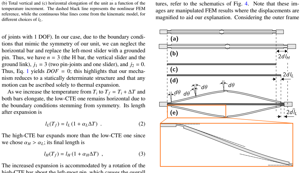
The central object is the symmetric displacement-amplifying unit: a low-CTE bar (beam 1) inside a high-CTE frame made of thick links (beams 3) joined by thin flexure hinges (beams 2 and 4). The load-bearing identity is the force balance between the frame and the bar, $F_H = k_H(2dl_H-2dl_L-2\bar{d}l_L) = k_L 2\bar{d}l_L = F_L$, where $k_H$ is obtained from the bending energy of the frame assuming a common end angle $d\theta$ for all bent members, and $k_L = E_L A_1/(2l_L)$ is the axial stiffness of the low-CTE bar. Solving it gives the extra elongation of the bar, $\bar{d}l_L = \frac{k_H}{k_H+k_L}(dl_H-dl_L)$, which is then inserted into the kinematic relation for the vertical displacement. What this machinery does is connect material choice and hinge geometry directly to the output expansion, producing design maps for $\alpha_\mathrm{eq}$ without running full finite element simulations.
What would settle it
The central claim predicts that a single epoxy-bonded unit reaches a vertical strain of about 0.8 at $\Delta T = 80\,^\circ\mathrm{C}$; measuring that strain directly, and repeating with $t_1=1$ mm and $t_1=4$ mm units to check the model's transferability, would settle both the magnitude of the effect and the validity of the mechanistic model.
Extended reading notes
Core claim
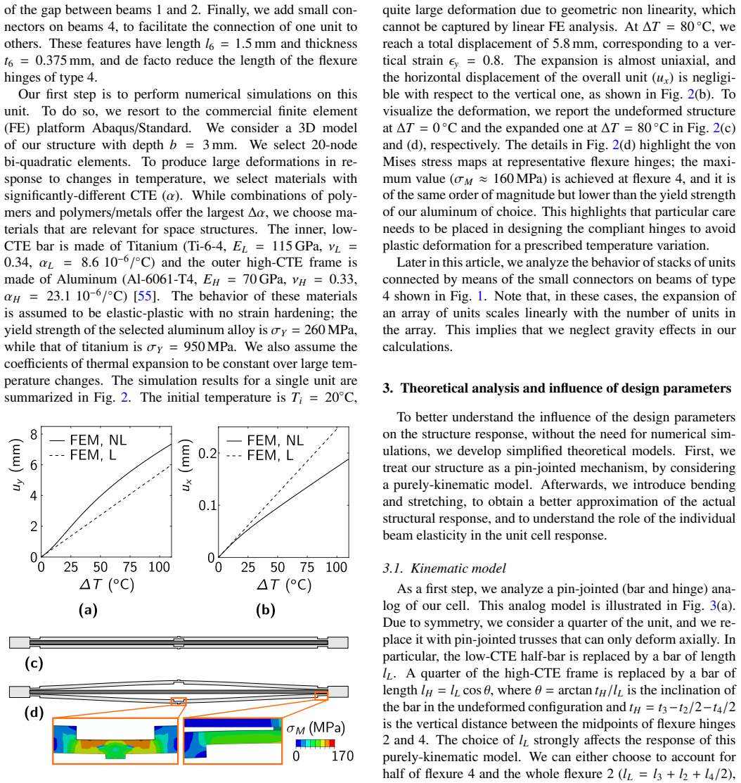
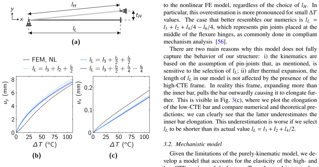
On the paper's own terms, the central discovery is that a deliberately compliant bi-metallic architecture can amplify the small thermal strains of metals into macroscopic, uniaxial expansion. The unit consists of a low-CTE titanium bar surrounded by a high-CTE aluminum frame whose beams are part bulky links and part thin flexure hinges; when heated, the frame's longitudinal expansion is constrained by the bar, so the excess expansion is channeled into bending of the hinges and appears as a large vertical displacement. In the default geometry, $\Delta T = 80\,^\circ\mathrm{C}$ produces a vertical strain $\epsilon_y = 0.8$ and an equivalent coefficient of thermal expansion $\alpha_\mathrm{eq} \approx 9.6\times10^{-3}/^\circ\mathrm{C}$, three orders of magnitude above the constituent metals. The mechanistic model treats every beam of the frame as bending through a common small angle $d\theta$, derives the frame's axial stiffness $k_H$ from the bending energy, balances it against the bar's stiffness $k_L$ via $k_H(2dl_H-2dl_L-2\bar{d}l_L)=k_L 2\bar{d}l_L$, and feeds the updated elongations into the pin-jointed kinematic relation $u_y = 2\left(\sqrt{l_H(T_f)^2-l_L(T_f)^2}-t_H\right)$; with $l_L=l_3+l_2+l_4/2$ it matches the nonlinear finite element curves and the experimental specimen bonded with epoxy before assembly. The paper demonstrates arrays of ten units, where expansion scales linearly with unit count, and a triangular-prism assembly whose three faces expand at different rates and therefore tilt during heating.
Load-bearing premise
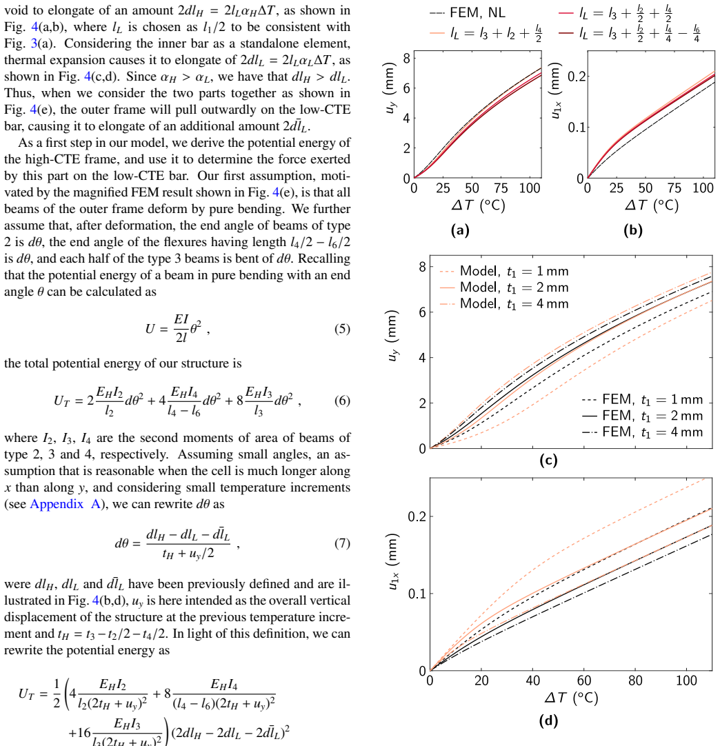
The load-bearing premise is that the whole high-CTE frame can be represented by one shared small bend angle $d\theta$ with an effective hinge spacing $l_L = l_3+l_2+l_4/2$; that spacing is chosen in part to match the nonlinear finite element reference for the default geometry, and the paper reports that agreement degrades when the low-CTE bar thickness is changed to 1 mm or 4 mm.
Editorial extensions
If this is right
- Stacks of $N$ units expand linearly in $N$: a ten-unit array reaches about 58 mm of vertical elongation at $\Delta T = 80\,^\circ\mathrm{C}$, so larger strokes come from adding units rather than changing materials.
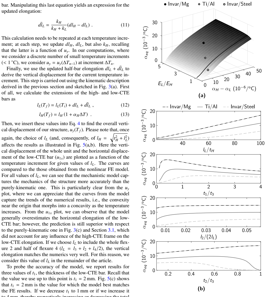
- The equivalent CTE can be tuned over orders of magnitude by material pair and geometry: the model gives $\alpha_\mathrm{eq}\approx 14.7\times10^{-3}/^\circ\mathrm{C}$ for Invar/Mg and $4.6\times10^{-3}/^\circ\mathrm{C}$ for Invar/steel, alongside $9.6\times10^{-3}/^\circ\mathrm{C}$ for Ti/Al.
- With a longer flexure 4, the same unit can cycle over the full lunar temperature range ($-173$ to $127\,^\circ\mathrm{C}$) while the maximum von Mises stress stays below the aluminum yield stress, so passive deployment and retraction are realistic.
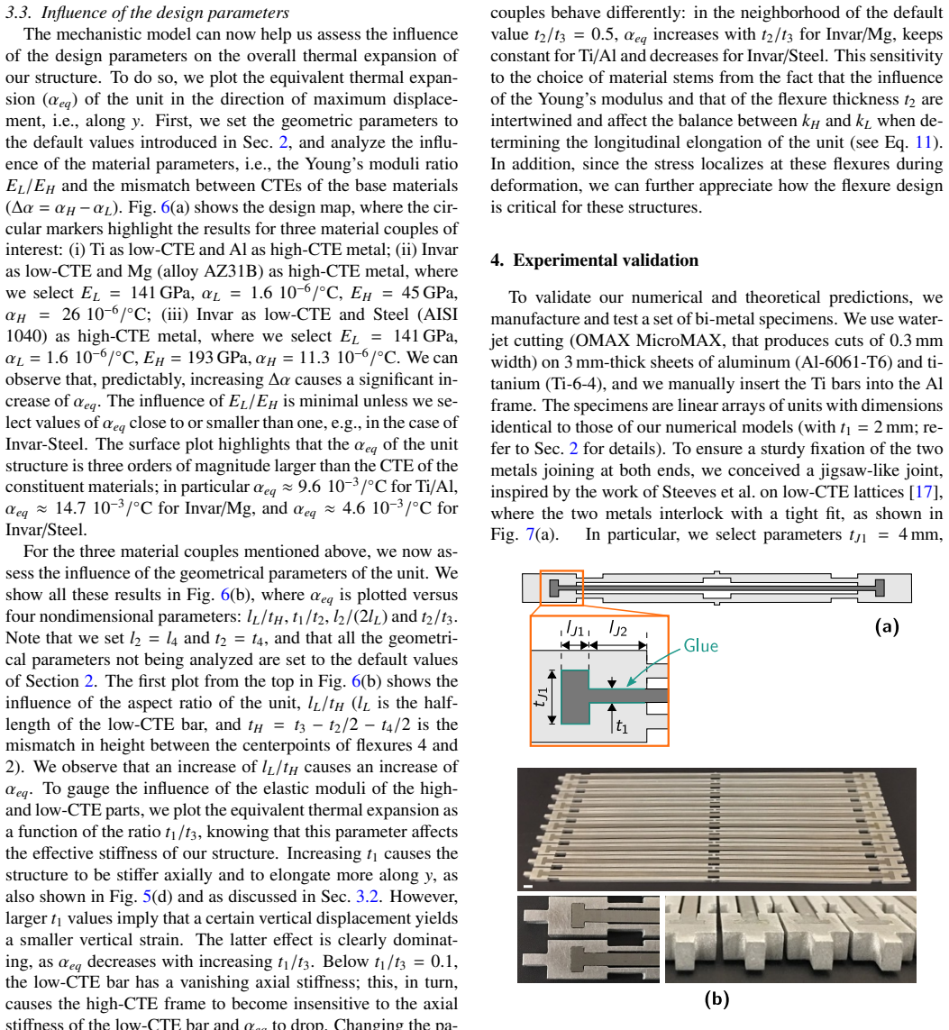
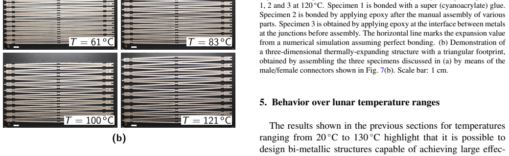
- Bonding strategy controls performance: epoxy applied before assembly gives expansion that matches the perfect-bonding prediction, whereas cyanoacrylate reduces the array expansion by about 25%, and differential bonding across an assembly produces nonuniform, out-of-plane deformation.
Reading between the lines
- Beyond the paper, the same unit could be treated as a programmable building block: by deliberately assigning different hinge lengths or material pairs to different portions of a panel, the differential expansion demonstrated in the triangular-prism experiment could be formalized into a design method for prescribed bending or twisting.
- Because the mechanism relies on elastic hinge bending rather than a phase transition, it should extend to other metal pairs and temperature windows as long as hinge stresses stay below yield; a natural test is multi-metal additive manufacturing of the whole unit, which would remove the bond-line variability that the paper shows dominates specimen-to-specimen differences.
- The calibration of $l_L = l_3+l_2+l_4/2$ to the default finite element solution leaves room for a stronger derivation from hinge kinematics; if such a derivation succeeded, the model's known discrepancies at $t_1=1$ mm and $t_1=4$ mm would be a direct target for improvement.
Signed reviews
Editorial analysis
A structured set of objections, weighed in public.
Referee Report
Summary. The paper presents a bi-metallic displacement-amplifying unit cell: a low-CTE titanium bar is embedded in a high-CTE aluminum frame with flexure hinges, so that heating produces a large vertical expansion. Nonlinear FE simulations predict a vertical strain of about 0.8 at ΔT = 80 °C and an equivalent CTE αeq ≈ 9.6×10^-3 /°C. The authors develop two analytical models: a purely kinematic pin-jointed model and a mechanistic model that adds frame elasticity through a pure-bending energy ansatz. They validate the FE and mechanistic predictions experimentally on 10-unit arrays manufactured by water-jet cutting, with three bonding strategies, and they demonstrate a triangular-prism 3D assembly. They also present a lunar-environment design that remains elastic over -173 °C to 127 °C.
Significance. If the results hold as stated, the paper demonstrates that ordinary aerospace metals can be arranged into compliant structures that produce large, passive, reversible thermal shape changes without exotic materials. This is a useful and credible contribution to the literature on thermal-expansion metamaterials and thermally actuated space structures. The experimental work is a particular strength: three repeated runs per point, thermal-camera temperature measurement, and good agreement for the epoxy-pre-bonded specimen 3. The mechanistic model also captures the qualitative nonlinear trend of the FE results. The main limitation is that the model's effective hinge length is selected to match FE at one geometry, so its predictive reach beyond that geometry is not independently established.
major comments (3)
- [Section 3.2 and Fig. 5(a,b)] The mechanistic model is calibrated, not fully derived, at the default geometry. Section 3.1 lists three candidate values for the effective length lL, and Section 3.2 selects lL = l3 + l2 + l4/2 because that choice makes the predicted uy match the nonlinear FE result. The agreement in Fig. 5(a,b) is therefore partly constructed. Fig. 5(c,d) further shows that for t1 = 1 mm and t1 = 4 mm the model's uy and u1x deviate from FE, which the authors attribute to the equal-angle bending and pin-jointed kinematics assumptions. Since Fig. 6 uses this same model to generate design maps over material and geometry ranges, those maps are extrapolations from a single calibrated point. Please either provide FE or experimental validation at off-default geometries, or reframe Fig. 6 as an interpolation around the calibrated design with quantified uncertainty, and temper the abstract and conclusion claim that the theoretical model is validated by experiments.
- [Section 3.2, Eqs. (6)-(8), and Appendix A] The stiffness expression kH is built on the assumption that every beam of the high-CTE frame deforms by the same end rotation dθ, including the type 2 beams, both halves of the type 3 beams, and the type 4 flexures. This is an ansatz; no equilibrium or compatibility derivation is provided, and Appendix A's Eq. (A.2) additionally assumes duy is small. The paper itself notes that this assumption breaks for bulky flexures and large t2/t3. Because Fig. 6(b) sweeps t2/t3, the non-monotonic behavior reported there for different material couples should be presented as a model prediction pending independent verification, not as a validated design rule.
- [Section 4 and Fig. 10(a)] The experimental validation covers only the default geometry and, among the three bonding strategies, only specimen 3 (epoxy applied before assembly) agrees closely with the FE and mechanistic predictions; specimens 1 and 2 deviate by up to about 25%. This does not undermine the demonstration that large passive thermal morphing is achievable, but it does mean the claim that the theoretical model is 'validated by experiments' should be qualified to this specific geometry and bonding protocol. The manuscript should also state explicitly that no off-default geometry was tested experimentally.
minor comments (5)
- [Section 1] There is a typo in the introduction: 'properteis' should be 'properties'.
- [Section 3.1] The definition of lH is geometrically inconsistent with its use in Eq. (4). The text states lH = lL cosθ with θ = arctan(tH/lL), but Eq. (4) treats lH as the hypotenuse of the triangle with legs lL and tH, i.e., lH = sqrt(lL^2 + tH^2). This should be corrected so that the quarter-cell geometry is unambiguous.
- [Section 3.1] In the sentence 'this model overestimates the vertical displacement ... regardless of the choice of lH', the symbol lH appears where lL is presumably meant, since the preceding discussion concerns three choices of lL.
- [Section 2 and Introduction] The claim that the structure 'almost doubles its width' over 100 °C is an extrapolation: the FE results in Fig. 2 are shown up to ΔT = 80 °C, where the vertical strain is about 0.8. The text should state that this is a projection for ΔT = 100 °C rather than a directly simulated or measured value.
- [General] Raw measurement data and the CAD/FE models are not provided; adding a data-availability statement listing the experimental mean and standard deviation values would improve reproducibility.
Circularity Check
The mechanistic model's effective hinge length lL is selected to match the nonlinear FE vertical-displacement curve at the default geometry, so the Fig. 6 design maps are calibrated extrapolations; the experimental demonstration of large thermal morphing is nevertheless independent.
-
fitted input called prediction
[Section 3.2 (Mechanistic model), lL selection, Figs. 5(a,b); used for design maps in Section 3.3, Fig. 6.]
"Please note that, once again, the choice of lL (and, consequently, of lH = sqrt(tH^2 + lL^2)) affects the results as illustrated in Fig. 5(a,b)... If we choose lL to include the whole flexure 2 and half of flexure 4 (lL = l3 + l2 + l4/2), the vertical elongation matches the numerics very well. For this reason, we consider this value of lL in the remainder of the article."
The mechanistic model's effective pin-jointed length lL is not derived from a first-principles rule; the paper tests three plausible assignments and retains the one that makes the predicted vertical elongation of Eqs. (8)-(11) with Eq. (4) match the nonlinear FE curve at the default geometry. The agreement at that geometry is therefore a selection criterion, not an independent prediction. The same calibrated lL is then used to generate the equivalent-CTE design maps of Fig. 6 and the parameter studies of Section 3.3. The paper itself reports in Fig. 5(c) that the model's agreement degrades for t1 = 1 mm and t1 = 4 mm, which confirms that the calibration is local and that the off-default predictions are extrapolations rather than validated predictions.
full rationale
The only substantive circular step is the calibration of lL in the mechanistic model. Section 3.2 selects lL = l3 + l2 + l4/2 among candidates because it matches the nonlinear FE vertical-displacement curve at the default geometry, and Fig. 5(c) then shows larger discrepancies for t1 = 1 mm and 4 mm. Thus the model's agreement at the default geometry is partly imposed by the choice of lL, and the Fig. 6 design maps built on that lL are calibrated extrapolations rather than fully first-principles predictions. No load-bearing self-citation or imported uniqueness theorem is present: the citation to prior Pasini-group work [35] is contextual inspiration, and the compliant-mechanism hinge rule [56] is standard textbook practice. The paper's central experimental claim—large, reversible passive thermal morphing of bi-metallic units—rests on independent nonlinear FE results (Fig. 2) and direct measurements on 10-unit arrays (Fig. 9), so the circularity is localized to the mechanistic model's predictive reach and does not undermine the demonstrated phenomenon. Accordingly, the score is 4 rather than 0 or 6.
Assumptions & free parameters
free parameters (1)
- lL (effective half-length of the low-CTE bar in the pin-jointed analog) =
l3 + l2 + l4/2 = 88 mm for the default geometry
assumptions (5)
- domain assumption Euler-Bernoulli pure-bending potential U = EIθ^2/(2l) applies to all flexures and beams with equal end angle dθ.
- domain assumption Perfect bonding between the Al frame and Ti bar at the interface.
- domain assumption Out-of-plane thickness is sufficient for in-plane deformation, and gravity is neglected in array calculations.
- domain assumption Materials are elastic-perfectly plastic with no strain hardening, and CTE is constant in Sections 2-4.
- standard math Gruebler DOF equation and the trigonometric pin-jointed kinematics in Eq. (4) describe the unit's expansion.
Cite this review
Pith. "Pith review of Temperature-induced shape morphing of bi-metallic structures." pith.science (2026). https://pith.science/paper/QSOJSEE2
@misc{pith2026190801088,
  author       = {Pith},
  title        = {Pith review of: Temperature-induced shape morphing of bi-metallic structures},
  year         = {2026},
  howpublished = {\url{https://pith.science/paper/QSOJSEE2}},
  note         = {Machine review of arXiv:1908.01088}
}
read the original abstract
In this work, we study the thermo-mechanical behavior of metallic structures designed to significantly change shape in response to thermal stimuli. This behavior is achieved by arranging two metals with different coefficient of thermal expansion (CTE), Aluminum and Titanium, as to create displacement-amplifying units that can expand uniaxially. In particular, our design comprises a low-CTE bar surrounded by a high-CTE frame that features flexure hinges and thicker links. When the temperature increases, the longitudinal expansion of the high-CTE portion is geometrically constrained by the low-CTE bar, resulting in a large tangential displacement. Our design is guided by theoretical models and numerical simulations. We validate our approach by fabricating and characterizing individual units, one dimensional arrays and three-dimensional structures. Our work shows that structurally robust metallic structures can be designed for large shape changes. The results also demonstrate how harsh environmental conditions (e.g., the extreme temperature swings that are characteristic of extraterrestrial environments) can be leveraged to produce function in a fully passive way.
Figures

Figures from the paper (8 more)



Reference graph
Works this paper leans on
-
[1]
K. Yoshida, H. Morigami, Thermal properties of diamond /copper com- posite material, Microelectronics reliability 44 (2) (2004) 303–308
work page 2004
-
[2]
G. A. Slack, S. Bartram, Thermal expansion of some diamondlike crys- tals, Journal of Applied Physics 46 (1) (1975) 89–98
work page 1975
-
[3]
R. Roy, D. K. Agrawal, H. A. McKinstry, Very low thermal expansion coefficient materials, Annual Review of Materials Science 19 (1) (1989) 59–81
work page 1989
-
[4]
T. Mary, J. Evans, T. V ogt, A. Sleight, Negative thermal expansion from 0.3 to 1050 kelvin in zrw2o8, Science 272 (5258) (1996) 90–92
work page 1996
-
[5]
B. K. Greve, K. L. Martin, P. L. Lee, P. J. Chupas, K. W. Chapman, A. P. Wilkinson, Pronounced negative thermal expansion from a simple structure: cubic scf3, Journal of the American Chemical Society 132 (44) (2010) 15496–15498
work page 2010
-
[6]
D. Das, T. Jacobs, L. J. Barbour, Exceptionally large positive and negative anisotropic thermal expansion of an organic crystalline material, Nature materials 9 (1) (2010) 36
work page 2010
-
[7]
I. Grobler, V . J. Smith, P. M. Bhatt, S. A. Herbert, L. J. Barbour, Tun- able anisotropic thermal expansion of a porous zinc (ii) metal–organic framework, Journal of the American Chemical Society 135 (17) (2013) 6411–6414
work page 2013
-
[8]
O. Sigmund, S. Torquato, Composites with extremal thermal expansion coefficients, Applied Physics Letters 69 (21) (1996) 3203–3205. 11
work page 1996
Show all 61 references
-
[9]
Lakes, Cellular solids with tunable positive or negative thermal expan- sion of unbounded magnitude, Applied Physics Letters 90 (22) (2007) 221905
R. Lakes, Cellular solids with tunable positive or negative thermal expan- sion of unbounded magnitude, Applied Physics Letters 90 (22) (2007) 221905. doi:10.1063/1.2743951
2007 doi
-
[10]
Je fferson, T
G. Je fferson, T. A. Parthasarathy, R. J. Kerans, Tailorable thermal ex- pansion hybrid structures, International Journal of Solids and Structures 46 (11-12) (2009) 2372–2387. doi:10.1016/j.ijsolstr.2009.01. 023
2009 doi
-
[11]
K. Wei, H. Chen, Y . Pei, D. Fang, Planar lattices with tailorable coefficient of thermal expansion and high sti ffness based on dual-material triangle unit, Journal of the Mechanics and Physics of Solids 86 (2016) 173–191. doi:10.1016/j.jmps.2015.10.004
2016 doi
-
[12]
K. Wei, Y . Peng, Z. Qu, Y . Pei, D. Fang, A cellular metastructure in- corporating coupled negative thermal expansion and negative poisson’s ratio, International Journal of Solids and Structures 150 (2018) 255–267. doi:https://doi.org/10.1016/j.ijsolstr.2018.06.018
2018 doi
-
[13]
Y . Li, Y . Chen, T. Li, S. Cao, L. Wang, Hoberman-sphere-inspired lat- tice metamaterials with tunable negative thermal expansion, Composite Structures 189 (2018) 586–597. doi:10.1016/j.compstruct.2018. 01.108
2018 doi
-
[14]
R. C. Wetherhold, J. Wang, Tailoring thermal deformation by using lay- ered beams, Composites science and technology 53 (1) (1995) 1–6
1995
-
[15]
T. A. Schaedler, W. B. Carter, Architected cellular materials, Annual Review of Materials Research 46 (1) (2016) 187–210. doi:10.1146/ annurev-matsci-070115-031624
2016
-
[16]
Sigmund, S
O. Sigmund, S. Torquato, Design of materials with extreme thermal ex- pansion using a three-phase topology optimization method, Journal of the Mechanics and Physics of Solids 45 (6) (1997) 1037–1067
1997
-
[17]
C. A. Steeves, S. L. d. S. e Lucato, M. He, E. Antinucci, J. W. Hutchin- son, A. G. Evans, Concepts for structurally robust materials that combine low thermal expansion with high stiffness, Journal of the Mechanics and Physics of Solids 55 (9) (2007) 1803–1822
2007
-
[18]
Berger, C
J. Berger, C. Mercer, R. M. McMeeking, A. G. Evans, The design of bonded bimaterial lattices that combine low thermal expansion with high stiffness, Journal of the American Ceramic Society 94 (s1) (2011) s42– s54. doi:10.1111/j.1551-2916.2011.04503.x
2011
-
[19]
Gdoutos, A
E. Gdoutos, A. Shapiro, C. Daraio, Thin and thermally stable periodic metastructures, Experimental mechanics 53 (9) (2013) 1735–1742
2013
-
[20]
E. M. Parsons, Lightweight cellular metal composites with zero and tun- able thermal expansion enabled by ultrasonic additive manufacturing: Modeling, manufacturing, and testing, Composite Structures 223 (2019) 110656. doi:10.1016/j.compstruct.2019.02.031
2019 doi
-
[21]
Yamamoto, E
N. Yamamoto, E. Gdoutos, R. Toda, V . White, H. Manohara, C. Daraio, Thin films with ultra-low thermal expansion, Advanced Materials 26 (19) (2014) 3076–3080. doi:10.1002/adma.201304997
2014 doi
-
[22]
H. Xu, A. Farag, D. Pasini, Multilevel hierarchy in bi-material lattices with high specific sti ffness and unbounded thermal expansion, Acta Ma- terialia 134 (2017) 155–166
2017
-
[23]
H. Xu, D. Pasini, Structurally-e fficient three-dimensional metamaterials with controllable thermal expansion, Scientific Reports 6 (2016) 34924. doi:10.1038/srep34924
2016 doi
-
[24]
H. Xu, A. Farag, D. Pasini, Routes to program thermal expansion in three- dimensional lattice metamaterials built from tetrahedral building blocks, Journal of the Mechanics and Physics of Solids 117 (2018) 54–87. doi: https://doi.org/10.1016/j.jmps.2018.04.012
2018 doi
-
[25]
Q. Wang, J. A. Jackson, Q. Ge, J. B. Hopkins, C. M. Spadaccini, N. X. Fang, Lightweight mechanical metamaterials with tunable neg- ative thermal expansion, Physical Review Letters 117 (2016) 175901. doi:10.1103/PhysRevLett.117.175901
2016 doi
-
[26]
J. Qu, M. Kadic, A. Naber, M. Wegener, Micro-structured two-component 3d metamaterials with negative thermal-expansion coe fficient from pos- itive constituents, Scientific Reports 7 (2017) 40643. doi:10.1038/ srep40643
2017
-
[27]
H. Heo, K. Kim, A. Tessema, A. Kidane, J. Ju, Thermomechanically tunable elastic metamaterials with compliant porous structures, Jour- nal of Engineering Materials and Technology 140 (2) (2017) 021004. doi:10.1115/1.4038029
2017 doi
-
[28]
D. G. Gilmore, Spacecraft Thermal Control Handbook V olume I: Funda- mental Technologies, Aerospace Corp, 2002
2002
-
[29]
Athanasopoulos, N
N. Athanasopoulos, N. J. Siakavellas, Smart patterned surfaces with pro- grammable thermal emissivity and their design through combinatorial strategies, Scientific reports 7 (1) (2017) 12908
2017
-
[30]
Sung, Smart geometries for smart materials: Taming thermobimetals to behave, Journal of Architectural Education 70 (1) (2016) 96–106.doi: 10.1080/10464883.2016.1122479
D. Sung, Smart geometries for smart materials: Taming thermobimetals to behave, Journal of Architectural Education 70 (1) (2016) 96–106.doi: 10.1080/10464883.2016.1122479
2016
-
[31]
Boatti, N
E. Boatti, N. Vasios, K. Bertoldi, Origami metamaterials for tunable thermal expansion, Advanced Materials 29 (26) (2017) 1700360. doi: 10.1002/adma.201700360
2017 doi
-
[32]
Y . Tang, G. Lin, S. Yang, Y . K. Yi, R. D. Kamien, J. Yin, Programmable kiri-kirigami metamaterials, Advanced Materials 29 (10) (2017) 1604262. doi:10.1002/adma.201604262
2017 doi
-
[33]
J. Cui, J. G. M. Adams, Y . Zhu, Pop-up assembly of 3d structures actu- ated by heat shrinkable polymers, Smart Materials and Structures 26 (12) (2017) 125011. doi:10.1088/1361-665X/aa9552
2017 doi
-
[34]
Han, S.-H
M.-W. Han, S.-H. Ahn, Blooming Knit Flowers: Loop-Linked Soft Mor- phing Structures for Soft Robotics, Advanced Materials 29 (13) (2017) 1606580. doi:10.1002/adma.201606580
2017 doi
-
[35]
H. Xu, A. Farag, R. Ma, D. Pasini, Thermally actuated hierarchical lat- tices with large linear and rotational expansion, Journal of Applied Me- chanics x (x) (2019) 1–32. doi:10.1115/1.4044026
2019 doi
-
[36]
Kotikian, R
A. Kotikian, R. L. Truby, J. W. Boley, T. J. White, J. A. Lewis, 3d printing of liquid crystal elastomeric actuators with spatially programed nematic order, Advanced Materials 30 (10) (2018) 1706164. doi:10.1002/ adma.201706164
2018
-
[37]
D. J. Hartl, D. C. Lagoudas, Aerospace applications of shape memory alloys, Proceedings of the Institution of Mechanical Engineers, Part G: Journal of Aerospace Engineering 221 (4) (2007) 535–552. doi:10. 1243/09544100JAERO211
2007
-
[38]
E. A. Peraza-Hernandez, D. J. Hartl, R. J. Malak, Design and numeri- cal analysis of an SMA mesh-based self-folding sheet, Smart Materials and Structures 22 (9) (2013) 094008. doi:10.1088/0964-1726/22/ 9/094008
2013 doi
-
[39]
C. Yuan, Z. Ding, T. J. Wang, M. L. Dunn, H. J. Qi, Shape form- ing by thermal expansion mismatch and shape memory locking in poly- mer/elastomer laminates, Smart Materials and Structures 26 (10) (2017) 105027. doi:10.1088/1361-665x/aa8241
2017 doi
-
[40]
Idogaki, T
T. Idogaki, T. Tominaga, K. Senda, N. Ohya, T. Hattori, Bending and expanding motion actuators, Sensors and Actuators A: Physical 54 (1) (1996) 760–764. doi:10.1016/S0924-4247(97)80053-2
1996 doi
-
[41]
J. D. Ervin, D. Brei, Recurve piezoelectric-strain-amplifying actuator ar- chitecture, IEEE/ASME Transactions on Mechatronics 3 (4) (1998) 293–
1998
-
[42]
Jaenker, Electrostrictive or piezoelectric actuator device with a stroke amplifying transmission mechanism (Sep
P. Jaenker, Electrostrictive or piezoelectric actuator device with a stroke amplifying transmission mechanism (Sep. 2001)
2001
-
[43]
J. H. Kim, S. H. Kim, Y . K. Kwak, Development and optimization of 3-D bridge-type hinge mechanisms, Sensors and Actuators A: Physical 116 (3) (2004) 530–538. doi:10.1016/j.sna.2004.05.027
2004 doi
-
[44]
Juuti, K
J. Juuti, K. Kords, R. Lonnakko, V .-P. Moilanen, S. Leppvuori, Mechan- ically amplified large displacement piezoelectric actuators, Sensors and Actuators A: Physical 120 (1) (2005) 225–231. doi:10.1016/j.sna. 2004.11.016
2005 doi
-
[45]
Muraoka, S
M. Muraoka, S. Sanada, Displacement amplifier for piezoelectric actuator based on honeycomb link mechanism, Sensors and Actuators A: Physical 157 (1) (2010) 84–90. doi:10.1016/j.sna.2009.10.024
2010 doi
-
[46]
P. A. York, N. T. Ja fferis, R. J. Wood, Meso scale flextensional piezo- electric actuators, Smart Materials and Structures 27 (1) (2017) 015008. doi:10.1088/1361-665x/aa9366
2017 doi
-
[47]
Feenstra, J
J. Feenstra, J. Granstrom, H. Sodano, Energy harvesting through a back- pack employing a mechanically amplified piezoelectric stack, Mechanical Systems and Signal Processing 22 (3) (2008) 721–734. doi:10.1016/ j.ymssp.2007.09.015
2008
-
[48]
D. J. Clingman, G. Pena, Broadband energy harvester apparatus and method (Oct. 2008)
2008
-
[49]
G. Acar, C. Yilmaz, Experimental and numerical evidence for the ex- istence of wide and deep phononic gaps induced by inertial amplifica- tion in two-dimensional solid structures, Journal of Sound and Vibration 332 (24) (2013) 6389–6404
2013
-
[50]
Taniker, C
S. Taniker, C. Yilmaz, Design, analysis and experimental investigation of three-dimensional structures with inertial amplification induced vibration stop bands, International Journal of Solids and Structures 72 (2015) 88– 97
2015
-
[51]
Taniker, C
S. Taniker, C. Yilmaz, Generating ultra wide vibration stop bands by a novel inertial amplification mechanism topology with flexure hinges, In- 12 ternational Journal of Solids and Structures 106 (2017) 129–138
2017
-
[52]
L. L. Howell, T. W. McLain, Techniques in the design of thermomechan- ical microactuators, in: C. T. Leondes (Ed.), MEMS /NEMS Handbook, Techniques and Applications, V ol. 4, Springer, 2006, Ch. 7, pp. 187–200
2006
-
[53]
L. Wu, B. Li, J. Zhou, Enhanced thermal expansion by micro- displacement amplifying mechanical metamaterial, MRS Advances 3 (8-
-
[54]
H. Heo, S. Li, H. Bao, J. Ju, A passive thermal switch with kirigami- inspired mesostructures, Advanced Engineering Materials 0 (0) (2019) 1900225. doi:10.1002/adem.201900225
2019 doi
- [55]
-
[56]
Howell, Compliant Mechanisms, Wiley, 2001
L. Howell, Compliant Mechanisms, Wiley, 2001
2001
-
[57]
Ashby, Materials Selection in Mechanical Design, 5th Edition, Butterworth-Heinemann, Berlin; New York, 2016
M. Ashby, Materials Selection in Mechanical Design, 5th Edition, Butterworth-Heinemann, Berlin; New York, 2016
2016
-
[58]
Y . S. Touloukian, R. K. Kirby, R. E. Taylor, P. Desai (Eds.), Thermophys- ical properties of matter, V ol. 12, Plenum, New York, 1979
1979
-
[59]
E. D. Marquardt, J. P. Le, R. Radebaugh, Cryogenic Material Properties Database, Springer US, Boston, MA, 2002, pp. 681–687
2002
-
[61]
Nibennaoune, D
Z. Nibennaoune, D. George, S. Ahzi, D. Ruch, Y . Remond, J. Gracio, Numerical simulation of residual stresses in diamond coating on ti-6al-4v substrate, Thin Solid Films 518 (12) (2010) 3260–3266. doi:10.1016/ j.tsf.2009.12.092. 13
2010
-
[301]
doi:10.1109/3516.736163
Reviewed August 14, 2026 · model on record in the stance chip above.
Discussion (0). Continue with ORCID to comment.