REVIEW 3 major objections 5 minor 61 references
Applying the Fokker--Planck equation to grating-based x-ray phase and dark-field imaging
T0 review · 3 major / 5 minor · reviewed 2026-08-14 · deepseek-v4-flash
Pith's one-line read Applying the finite-difference X-ray Fokker–Planck equation to sinusoidal grating illumination yields analytic formulas for dark-field edge effects, phase focusing, and phase-edge cross-talk.
desk verdict A solid theory paper with new analytic expressions for cross-talk artifacts, but an unresolved ambiguity about the diffusion coefficient in the central finite-difference equation. read the letter →
The pith
A machine-rendered reading of the paper's core claim, the machinery that carries it, and where it could break.
The reading
What carries the argument
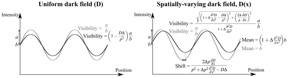
The load-bearing object is the finite-difference X-ray Fokker–Planck map, Eq. (6), obtained by replacing time with propagation distance $z$ in the classical Fokker–Planck equation: intensity $I$ plays the role of probability density, the drift coefficient is $(1/k)\partial_x\varphi$ (the sample-induced phase gradient), and the diffusion coefficient $D(x,z)$ encodes unresolved small-angle scattering. Inserting sinusoidal illumination $I=a\sin(x/p)+b$ into that map is what makes the analysis explicit: uniform diffusion multiplies the sinusoidal amplitude by $1-D\Delta/p^2$, a spatially varying $D$ generates local bright/dark bands through $\partial^2D/\partial x^2$ and an additional shift through $\partial D/\partial x$, and phase curvature $\partial^2\varphi/\partial x^2$ changes the mean, period, and shift of the pattern. The linearization in $\Delta$ makes drift and diffusion effects add, which is why a single combined formula, Eq. (25), can describe both.
What would settle it
Set up a directly-resolved absorbing or phase grating to illuminate a sharp boundary between two uniform scattering materials with known diffusion coefficients $D_\text{left}$ and $D_\text{right}$, and record intensity profiles for a range of propagation distances $\Delta$ and grating periods $p$. The model predicts a local bright/dark band in the mean intensity whose shape follows $\partial^2 D/\partial x^2$ and whose amplitude scales with $\Delta(D_\text{right}-D_\text{left})/p^2$, plus a visibility overshoot on the weakly scattering side. If the measured edge signature does not follow that shape or scaling, the diffusion model is falsified.
Extended reading notes
Core claim
The paper's central claim is that the finite-difference form of the X-ray Fokker–Planck equation, $$I(x,z=\$\Delta$)\approx I(x,z=0)+\$\Delta$\left[-\frac{1}{k}\frac{\partial}{\partial x}\left(I\frac{\partial\varphi}{\partial x}\right)+\frac{\$partial^{2}$}{\partial $x^{2}$}(D I)\right],$$ with the illuminating pattern taken as the sinusoid $I=a\sin(x/p)+b$, is a valid forward model for grating-based phase and dark-field x-ray imaging. Under this model the differential-phase signal is the drift term and the dark-field signal is the diffusion term. The paper derives explicit expressions for what happens where the sample changes: a scattering edge produces local extra bright and dark bands and visibility changes (Eqs. 12 and 16); a phase gradient shifts the grid pattern without changing visibility (Eq. 22); phase curvature focuses or defocuses the pattern, changing mean, period, and shift together (Eq. 23); a phase edge adds a bright/dark fringe (Eq. 24); and the two effects add (Eq. 25). The same machinery carries over to two-grating systems: the stepping curve of a grating interferometer has mean $pM/2$, visibility $V/2$, and shift $s$ (Eq. 28), and edge-illumination signals combine in the same way (Eqs. 29–30).
Load-bearing premise
The analysis stands on treating unresolved small-angle x-ray scattering as a genuine diffusion process governed by a single z-dependent coefficient $D(x,z)$ with negligible higher-order Kramers–Moyal terms; if scattering is non-Gaussian or has significant third-order terms, the predicted edge and lensing signatures will not match grating-based measurements.
Editorial extensions
If this is right
- At scattering edges, the predicted mean-intensity band and visibility change can be recognized as artifacts and subtracted, so dark-field images are not contaminated by edge signals.
- Strong phase curvature produces simultaneous changes in mean, period, and shift; the analytic expressions quantify how much apparent attenuation and dark-field a lensing object can create.
- Phase edges add a bright/dark fringe over the structured illumination, providing a grating-based analogue of propagation-based edge contrast that can be modelled rather than mistaken for sample structure.
- Since drift and diffusion terms add in the finite-difference approximation, Eq. (25) is a single forward model that can serve as the basis for joint phase/dark-field retrieval.
- For grating interferometry and edge illumination, the directly-resolved-grid results transfer with simple scalings: stepping-curve mean becomes $pM/2$, visibility becomes $V/2$, and the shift remains $s$.
Reading between the lines
- Extension beyond the paper: the same linearized model suggests a direct route to simultaneous phase and dark-field retrieval by inverting Eq. (25) for $\varphi$ and $D$, with edge terms included rather than treated as noise.
- Extension beyond the paper: because source-size blur, detector blur, and sample scattering would all enter as additive diffusion coefficients, the formalism gives a principled way to separate their contributions from measurements at different distances, grating periods, or source sizes.
- Extension beyond the paper: the visibility-zero condition $D\Delta=p^2$ (blur width equal to the grid period) implies a design trade-off, suggesting that the optimal grating period for dark-field sensitivity is set by the expected scattering length scale, not merely by resolution.
- Extension beyond the paper: since arbitrary illumination can be built from sinusoids by Fourier decomposition, the single-sinusoid formulas should transfer to speckle-tracking and non-periodic grid patterns, though the paper only gestures at this connection.
Signed reviews
Editorial analysis
A structured set of objections, weighed in public.
Referee Report
Summary. This paper proposes that the finite-difference form of a Fokker-Planck equation with an added diffusion term can describe the propagation of periodic (sinusoidal) intensity patterns in grating-based and speckle-based x-ray phase and dark-field imaging. The authors start from the X-ray Fokker-Planck equation (Eq. 2), and derive analytic expressions for dark-field visibility loss (Eq. 8), dark-field edge signatures (Eqs. 12 and 14), an integral representation for the large-blur regime (Eq. 16), the prism phase shift (Eq. 22), phase focusing and phase-edge effects (Eqs. 23 and 24), a combined phase/dark-field expression (Eq. 25), and extensions to grating interferometry and edge illumination (Eqs. 27-30). The results are benchmarked against known limiting cases, such as the Lynch et al. dark-field coefficient D/p^2 and the Morgan et al. prism shift. The paper includes Python code for interactive visualization of the derived formulas. No experimental validation is provided, and the central model equation is taken from an in-press companion paper.
Significance. If correct, the paper provides a valuable unifying framework in which phase drift and dark-field diffusion are described by a single partial differential equation, and it yields closed-form expressions for edge and focusing artifacts that are usually discussed only qualitatively in grating-interferometry literature. The benchmarking against independent known expressions and the reproducible code are strengths. However, several key displayed equations contain algebraic errors or ambiguities that affect the quantitative predictions, and the treatment of the z-dependent diffusion coefficient in the finite-difference step is unresolved. These issues must be fixed before the results can be used as a reliable quantitative basis.
major comments (3)
- [Sections 2 and 3.1.1, Eqs. (2), (6), (8), (9)] The paper states that D(x,z) is made z-dependent so that the blur width grows linearly with z, but the finite-difference approximation (6) and all subsequent dark-field results use a single constant D multiplied by Delta. If D(z) = D0 z is inserted into Eq. (2), the diffusion term at the initial plane z=0 vanishes, so a forward-Euler step gives no first-order-in-Delta dark-field contribution; evaluating D at z=Delta instead makes the term O(Delta^2). The manuscript never specifies what D in Eq. (6) represents (initial value, final value, or an integrated average), and the factor-of-two remark after Eq. (9) does not resolve this. Because Eqs. (8), (10), (12), (14), and (16) all inherit this step, the quantitative dark-field predictions rest on an unresolved internal inconsistency.
- [Section 3.2, Eqs. (21)-(25)] The phase-shift term in Eq. (21), namely tan^{-1}( (dphi/dx) p / (k/Delta - d2phi/dx2) ), does not follow from Eq. (20). Combining the sin and cos terms in Eq. (20) yields a phase shift of tan^{-1}[ (dphi/dx) / (p(k/Delta - d2phi/dx2)) ], so p belongs in the denominator rather than the numerator. Consequently Eq. (21) and the derived Eq. (23) contain an extra factor p^2 in the shift. Setting A=0 (a linear phase ramp) in Eq. (23) gives a shift B p^2 Delta/k instead of B Delta/k, contradicting Eq. (22) and the known prism shift. This error propagates into the phase-edge formula (24) and the combined formula (25), so the phase-related analytic results are not reliable in their current printed form.
- [Section 3.1.2, Eq. (16)] The large-blur convolution result is displayed as a complex expression involving imaginary error functions. The mean-intensity term contains 2b e^{(2ipx+(D_l+D_r)Delta)/(2p^2)} (2 - Erf(x/sqrt(2D_l Delta)) + Erf(x/sqrt(2D_r Delta))), whose oscillatory e^{ix/p} factor cannot arise from the constant contribution b of the illumination, and whose limiting value as x to +/- infinity is not b. This suggests a typographical or algebraic error in the displayed formula. Since Eq. (16) underlies the Python-based visualizations of the dark-field edge effect in the large-blur regime, it needs to be rederived and numerically verified.
minor comments (5)
- [Section 3.1.2, text below Eq. (13)] The sentence '...D = Dright far to the left of the origin, and D = Dleft to the right of the origin' is opposite to what Eq. (13) actually gives; it should read Dleft on the left and Dright on the right, consistent with Fig. 4.
- [Eq. (5) and Eq. (26)] Equation (5) omits the factor 2pi inside sin(x/p), but Eq. (26) reintroduces it; the authors should state explicitly that p in Eqs. (5)-(24) is a dimensionless spatial-frequency parameter and not the physical grating period, to avoid confusion.
- [Section 3.4.1, Eqs. (27)-(28)] The integration leading from Eq. (27) to Eq. (28) is not shown; a brief derivation or a statement of the orthogonality relation used would make the result easier to verify.
- [General, ref. [24]] The paper relies on an in-press companion paper for the central Fokker-Planck equation; the authors should confirm that the companion is published and include a short summary of the assumptions (paraxiality, projection approximation, etc.) in the present manuscript.
- [Section 3.1.1 and 3.2.2] The connection between the blur width L = sqrt(D Delta) and the z-dependent diffusion coefficient is stated in passing; a precise definition of D(z) and a short derivation of the resulting linear growth would help the reader understand the finite-difference treatment.
Circularity Check
No significant circularity: the assumed Fokker-Planck model is applied, not re-derived from its own outputs.
full rationale
The paper's derivations are self-contained once the stated input model is accepted. The X-ray Fokker-Planck equation (Eq. 2) is imported from the authors' companion paper (ref. 24), which is a self-citation, but it functions as the assumed physical model rather than as a result derived within this paper; the paper's contribution is the application of that model to sinusoidal structured illumination. The subsequent analytic results (Eqs. 8, 12, 14, 16, 21-25, and 28-30) follow by substituting the sinusoidal illumination of Eq. (5) into the finite-difference approximation of Eq. (6) and performing algebraic, trigonometric, and elementary integral manipulations. No parameter is fitted to experimental data, and known limiting cases are recovered from independent literature: the linear dark-field coefficient D/p^2 matches Lynch et al. (Eq. 19), and the prism shift matches Morgan et al. (Eq. 22). These are consistency checks, not circular inputs. The apparent tension between the z-dependent D discussed in Sec. 2 and the use of a single D in the one-step finite-difference Eq. (6) is an internal consistency or correctness concern about the validity of the linearization, not a circular reduction, because the claimed predictions are explicitly linear-in-Delta approximations of the assumed equation rather than a disguised restatement of the model's assumptions.
Assumptions & free parameters
assumptions (8)
- domain assumption The X-ray Fokker-Planck equation, Eq. (2), governs the paraxial evolution of x-ray intensity through samples with phase and unresolved scattering.
- domain assumption The intensity of the x-ray beam can be treated as a probability density function undergoing drift and diffusion.
- ad hoc to paper The diffusion coefficient D(x,z) is z-dependent so that the diffusive spread grows linearly with propagation distance.
- standard math Truncation of the Kramers-Moyal expansion at second order is valid (Pawula theorem).
- domain assumption A sinusoidal illumination, Eq. (5), is a sufficiently general model because any periodic or speckle illumination can be expanded in a Fourier series.
- standard math The finite-difference approximation in Eq. (6) is valid for small propagation distance Δ, i.e., DΔ < p^2.
- domain assumption The convolution form in Eq. (9) with a Gaussian kernel of variance D(x')Δ describes the diffusive propagation as a position-dependent point spread function.
- ad hoc to paper The error-function transition profile in Eq. (13) models a smooth edge between two scattering regions and enables closed-form evaluation of edge effects.
Cite this review
Pith. "Pith review of Applying the Fokker--Planck equation to grating-based x-ray phase and dark-field imaging." pith.science (2026). https://pith.science/paper/MUMMZDP2
@misc{pith2026190801452,
  author       = {Pith},
  title        = {Pith review of: Applying the Fokker--Planck equation to grating-based x-ray phase and dark-field imaging},
  year         = {2026},
  howpublished = {\url{https://pith.science/paper/MUMMZDP2}},
  note         = {Machine review of arXiv:1908.01452}
}
read the original abstract
X-ray imaging has conventionally relied upon attenuation to provide contrast. In recent years, two complementary modalities have been added; phase contrast and dark-field x-ray imaging, capturing weakly attenuating and sub-pixel sample structures respectively. These three modalities can be accessed using a crystal analyser, a grating interferometer or by looking at a directly-resolved grid, grating or speckle pattern. Grating and grid-based methods extract a differential phase signal by measuring how far a feature in the illumination has been shifted transversely due to the presence of a sample. The dark-field signal is extracted by measuring how the visibility of the structured illumination is decreased, typically due to the presence of sub-pixel structures in a sample. The strength of the dark-field signal may depend on the grating period, the pixel size and the set-up distances, and additional dark-field signal contributions may be seen as a result of strong phase effects or other factors. In this paper we show that the finite-difference form of the Fokker--Planck Equation can be applied to describe the drift (phase signal) and diffusion (dark-field signal) of the periodic or structured illumination used in phase contrast x-ray imaging with gratings, in order to better understand any cross-talk between attenuation, phase and dark-field x-ray signals. In future work, this mathematical description could be used as a basis for new approaches to the inverse problem of recovering both phase and dark-field information.
Figures


Figures from the paper (3 more)


Reference graph
Works this paper leans on
-
[1]
Momose, A., Takeda, T., Itai, Y . & Hirano, K. Phase–contrast x–ray computed tomography for observing biological soft tissues. Nat. Med. 2, 473–475 (1996)
work page 1996
-
[2]
Jud, C. et al. Dentinal tubules revealed with x-ray tensor tomography. Dent. Mater ,32, 1189–1195 (2016)
work page 2016
- [3]
-
[4]
& Schlenker, M
Cloetens, P., Barrett, R., Baruchel, J., Guigay, J.-P. & Schlenker, M. Phase objects in synchrotron radiation hard x-ray imaging. J. Phys. D: Appl. Phys. 29, 133–146 (1996)
1996
-
[5]
& Schelokov, I
Snigirev, A., Snigireva, I., Kohn, V ., Kuznetsov, S. & Schelokov, I. On the possibilities of x-ray phase contrast microimaging by coherent high-energy synchrotron radiation. Rev. Sci. Instrum. 66, 5486–5492 (1995)
1995
-
[6]
X-ray phase imaging with a grating interferometer
Weitkamp, T.et al. X-ray phase imaging with a grating interferometer. Opt. Express 13, 6296–6304 (2005)
2005
-
[7]
& Ziegler, E
David, C., Nöhammer, B., Solak, H. & Ziegler, E. Differential x-ray phase contrast imaging using a shearing interferometer. Appl. Phys. Lett. 81, 3287–3289 (2002)
2002
-
[8]
Pfeiffer, F. et al. Hard-x-ray dark-field imaging using a grating interferometer. Nat. Mat. 7, 134–137 (2008)
work page 2008
Show all 61 references
-
[9]
Momose, A. et al. Demonstration of x-ray talbot interferometry. Jpn. J. Appl. Phys. 42, L866–L868 (2003)
2003
-
[10]
Miao, H. et al. A universal moiré effect and application in x-ray phase-contrast imaging. Nat. Phys. 12, 830–834 (2016)
2016
-
[11]
& Speller, R
Olivo, A. & Speller, R. A coded-aperture technique allowing x-ray phase contrast imaging with conventional sources. Appl. Phys. Lett. 91, 074106 (2007)
2007
-
[12]
E., Kopace, R., Stein, A
Bennett, E. E., Kopace, R., Stein, A. F. & Wen, H. A grating-based single-shot x-ray phase contrast and diffraction method for in vivo imaging. Med. Phys. 37, 6047–6054 (2010)
2010
-
[13]
S., Paganin, D
Morgan, K. S., Paganin, D. M. & Siu, K. K. W. Quantitative single-exposure x-ray phase contrast imaging using a single attenuation grid. Opt. Express 19, 19781–19789 (2011)
2011
-
[14]
S., Paganin, D
Morgan, K. S., Paganin, D. M. & Siu, K. K. W. X-ray phase imaging with a paper analyzer. Appl. Phys. Lett. 100, 124102 (2012)
2012
-
[15]
& Peverini, L
Bérujon, S., Ziegler, E., Cerbino, R. & Peverini, L. Two-dimensional x-ray beam phase sensing. Phys. Rev. Lett. 108, 158102 (2012)
2012
-
[16]
Khelashvili, G. et al. A physical model of multiple-image radiography. Phys. Med. Biol. 51, 221–236 (2005)
2005
-
[17]
X-ray phase-contrast imaging
Endrizzi, M. X-ray phase-contrast imaging. Nucl. Instr . Meth. Phys. Res. A 878, 88–98 (2018)
2018
-
[18]
Michelson, A. A. Studies in Optics (Chicago Press, reprinted by Dover Publications Inc., 1995)
1995
-
[19]
& Momose, A
Yashiro, W. & Momose, A. Effects of unresolvable edges in grating-based x-ray differential phase imaging. Opt. Express 23, 9233–9251 (2015)
2015
-
[20]
Wolf, J. et al. Lens-term-and edge-effect in x-ray grating interferometry. Biomed. Opt. Express 6, 4812–4824 (2015)
2015
-
[21]
Chabior, M. et al. Beam hardening effects in grating-based x-ray phase-contrast imaging. Med. Phys. 38, 1189–1195 (2011)
2011
-
[22]
& Zanette, I
Zdora, M.-C., Thibault, P., Pfeiffer, F. & Zanette, I. Simulations of x-ray speckle-based dark-field and phase-contrast imaging with a polychromatic beam. J. Appl. Phys. 118, 113105 (2015)
2015
-
[23]
The F okker-Planck Equation: Methods of Solution and Applications (Springer Verlag, Berlin, 1989), 2 edn
Risken, H. The F okker-Planck Equation: Methods of Solution and Applications (Springer Verlag, Berlin, 1989), 2 edn
1989
-
[24]
Paganin, D. M. & Morgan, K. S. X-ray Fokker–Planck equation for paraxial imaging. Accept. Sci. Reports (2019)
2019
-
[25]
Teague, M. R. Deterministic phase retrieval: a Green’s function solution. J. Opt. Soc. Am. 73, 1434–1441 (1983)
1983
-
[26]
S., Siu, K
Morgan, K. S., Siu, K. K. W. & Paganin, D. M. The projection approximation and edge contrast for x-ray propagation-based phase contrast imaging of a cylindrical edge. Opt. Express 18, 9865–9878 (2010). 14/16
2010
-
[27]
Morgan, K. S. et al. A sensitive x-ray phase contrast technique for rapid imaging using a single phase grid analyzer. Opt. Lett. 38, 4605–4608 (2013)
2013
-
[28]
Rizzi, J. et al. X-ray phase contrast imaging and noise evaluation using a single phase grating interferometer. Opt. Express 21, 17340–17351 (2013)
2013
-
[29]
State of the art of x-ray speckle-based phase-contrast and dark-field imaging
Zdora, M.-C. State of the art of x-ray speckle-based phase-contrast and dark-field imaging. J. Imaging 4, 60 (2018)
2018
-
[30]
& Wolf, E
Mandel, L. & Wolf, E. Optical Coherence and Quantum Optics (Cambridge University Press, Cambridge, 1995)
1995
-
[31]
Jensen, T. H. et al. Directional x-ray dark-field imaging. Phys. Med. Biol. 55, 3317–3323 (2010)
2010
-
[32]
Pawula, R. F. Approximation of the linear Boltzmann equation by the Fokker–Planck equation. Phys. Rev. 162, 186–188 (1967)
1967
-
[33]
Lynch, S. K. et al. Interpretation of dark-field contrast and particle-size selectivity in grating interferometers. Appl. Opt. 50, 4310–4319 (2011)
2011
-
[34]
Bech, M. et al. Quantitative x-ray dark-field computed tomography. Phys. Med. Biol. 55, 5529–5539 (2010)
2010
-
[35]
Koenig, T. et al. On the origin and nature of the grating interferometric dark-field contrast obtained with low-brilliance x-ray sources. Phys. Med. Biol. 61, 3427–3442 (2016)
2016
-
[36]
Morgan, K. S. et al. Capturing and visualizing transient x-ray wavefront topological features by single-grid phase imaging. Opt. Express 24, 24435–24450 (2016)
2016
-
[37]
Schleede, S. et al. Emphysema diagnosis using x-ray dark-field imaging at a laser-driven compact synchrotron light source. Proc. Natl. Acad. Sci. U S A 109, 17880–17885 (2012)
2012
-
[38]
& Pfeiffer, F
Prade, F., Yaroshenko, A., Herzen, J. & Pfeiffer, F. Short-range order in mesoscale systems probed by x-ray grating interferometry. EPL 112, 68002 (2016)
2016
-
[39]
Imaging the ultrasmall-angle x-ray scattering distribution with grating interferometry
Modregger, P.et al. Imaging the ultrasmall-angle x-ray scattering distribution with grating interferometry. Phys. Rev. Lett. 108, 048101 (2012)
2012
-
[40]
Interpretation and utility of the moments of small-angle x-ray scattering distributions
Modregger, P.et al. Interpretation and utility of the moments of small-angle x-ray scattering distributions. Phys. Rev. Lett. 118, 265501 (2017)
2017
-
[41]
Laminate fibre structure characterisation of carbon fibre-reinforced polymers by x-ray scatter dark field imaging with a grating interferometer
Revol, V .et al. Laminate fibre structure characterisation of carbon fibre-reinforced polymers by x-ray scatter dark field imaging with a grating interferometer. NDT & E Int. 58, 64–71 (2013)
2013
-
[42]
& Stampanoni, M
Kagias, M., Wang, Z., Villanueva-Perez, P., Jefimovs, K. & Stampanoni, M. 2d-omnidirectional hard-x-ray scattering sensitivity in a single shot. Phys. Rev. Lett. 116, 093902 (2016)
2016
-
[43]
Jud, C. et al. Trabecular bone anisotropy imaging with a compact laser-undulator synchrotron x-ray source. Sci. reports 7, 14477 (2017)
2017
-
[44]
Jensen, T. H. et al. Directional x-ray dark-field imaging of strongly ordered systems. Phys. Rev. B 82, 214103 (2010)
2010
-
[45]
Potdevin, G. et al. X-ray vector radiography for bone micro-architecture diagnostics. Phys. Med. Biol. 57, 3451–3461 (2012)
2012
-
[46]
Yaroshenko, A. et al. Non-binary phase gratings for x-ray imaging with a compact talbot interferometer. Opt. Express 22, 547–556 (2014)
2014
-
[47]
Paganin, D. M. Coherent X-Ray Optics (Oxford University Press, Oxford, 2006)
2006
-
[48]
& Kajiwara, K
Yashiro, W., Noda, D. & Kajiwara, K. Effect of insufficient temporal coherence on visibility contrast in x-ray grating interferometry. Opt. Express 26, 1012–1027 (2018)
2018
-
[49]
E., Gao, D., Pogany, A
Wilkins, S., Gureyev, T. E., Gao, D., Pogany, A. & Stevenson, A. Phase-contrast imaging using polychromatic hard x-rays. Nature 384, 335–338 (1996)
1996
-
[50]
Irvine, S. et al. Assessment of the use of a diffuser in propagation-based x-ray phase contrast imaging. Opt. Express 18, 13478–13491 (2010)
2010
-
[51]
Morgan, K. S. et al. Measurement of hard x-ray coherence in the presence of a rotating random-phase-screen diffuser. Opt. Commun. 283, 216–225 (2010)
2010
-
[52]
& Browne, M
Morrison, G. & Browne, M. Dark-field imaging with the scanning transmission x-ray microscope. Rev. Sci. Instrum. 63, 611–614 (1992)
1992
-
[53]
& Uchida, F
Suzuki, Y . & Uchida, F. Dark-field imaging in hard x-ray scanning microscopy.Rev. Sci. Instrum. 66, 1468–1470 (1995). 15/16
1995
-
[54]
& Wolf, E
Born, M. & Wolf, E. Principles of Optics (Cambridge University Press, Cambridge, 1999), 7th edn
1999
-
[55]
The Bakerian lecture: On the theory of light and colours
Young, T. The Bakerian lecture: On the theory of light and colours. Phil. Trans. R. Soc. Lond. 92, 12–48 (1802)
-
[56]
Maggi, G. A. Sulla propagazione libera e perturbata delle onde luminose in un mezzo isotropo. Annali di Mat. II 16, 21–48 (1888)
-
[57]
Die Beugungswelle in der Kirchhoffschen Theorie der Beugungserscheinungen
Rubinowicz, A. Die Beugungswelle in der Kirchhoffschen Theorie der Beugungserscheinungen. Ann. Physik 53, 257–278 (1917)
1917
-
[58]
& Wolf, E
Miyamoto, K. & Wolf, E. Generalization of the Maggi–Rubinowicz theory of the boundary diffraction wave–Part I. J. Opt. Soc. Am. 52, 615–625 (1962)
1962
-
[59]
& Wolf, E
Miyamoto, K. & Wolf, E. Generalization of the Maggi–Rubinowicz theory of the boundary diffraction wave–Part II. J. Opt. Soc. Am. 52, 626–637 (1962)
1962
-
[60]
Keller, J. B. Geometrical theory of diffraction. J. Opt. Soc. Am. 52, 116–130 (1962)
1962
-
[61]
S., Siu, K
Morgan, K. S., Siu, K. K. W. & Paganin, D. M. The projection approximation versus an exact solution for x-ray phase contrast imaging, with a plane wave scattered by a dielectric cylinder. Opt. Commun. 283, 4601–4608 (2010). Acknowledgements We acknowledge useful discussions wi...
2010
Reviewed August 14, 2026 · model on record in the stance chip above.
Discussion (0). Continue with ORCID to comment.