REVIEW 3 major objections 4 minor 34 references
Cable-driven robotic interface for lower limb neuromechanics identification
T0 review · 3 major / 4 minor · reviewed 2026-08-14 · deepseek-v4-flash
Pith's one-line read A cable-driven robotic interface can identify hip, knee, and ankle neuromechanics in an upright posture without constraining the joints.
desk verdict Genuinely new cable-driven lower-limb platform; the validation claim is undercut by the paper's own cable compliance identification, so treat the impedance numbers with caution. read the letter →
The pith
A machine-rendered reading of the paper's core claim, the machinery that carries it, and where it could break.
The reading
What carries the argument
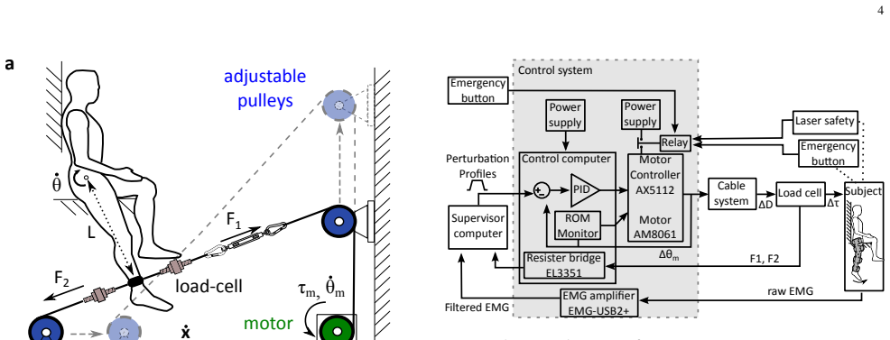
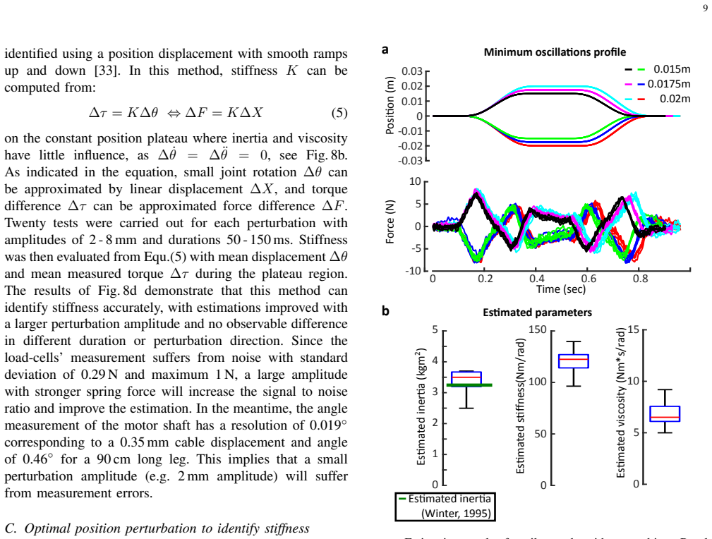
The central object is NED itself, a cable-driven endpoint interface whose actuator sits on the floor, connected by a pretensioned steel cable loop to a foot fixture with two load cells; lockable pulleys and an open seat let the same rig address hip, knee, or ankle. The load-bearing kinematics is the planar mapping $\dot{\theta} = \rho_m \dot{\theta}_m / L$ of Eq. (2), which turns motor-pulley motion into joint rotation, and the impedance identity of Eq. (4), which turns differential cable force $(F_1-F_2)L$ and joint angle into $I$, $B$, and $K$. The capstan equation $T_{\text{load}} = T_{\text{hold}} e^{\mu\phi}$ sizes the cable wrap to prevent slippage, and a 200 N pretension limits sagging-induced force error to below 2.5%. A smooth ramp-and-hold perturbation with a constant-position plateau lets Eq. (5), $\Delta\tau = K\Delta\theta$, read stiffness directly at the plateau because acceleration and velocity vanish there.
What would settle it
Instrument the leg endpoint with a motion capture marker and repeat the spring and dummy-leg identifications; if the endpoint displacement differs from the motor-encoder displacement by more than the paper's 5% error bound, the rigid-cable assumption is violated. Alternatively, fit the same data with the measured cable stiffness placed in series with the identified joint and check whether the estimated stiffness shifts by more than the reported variance.
Extended reading notes
Core claim
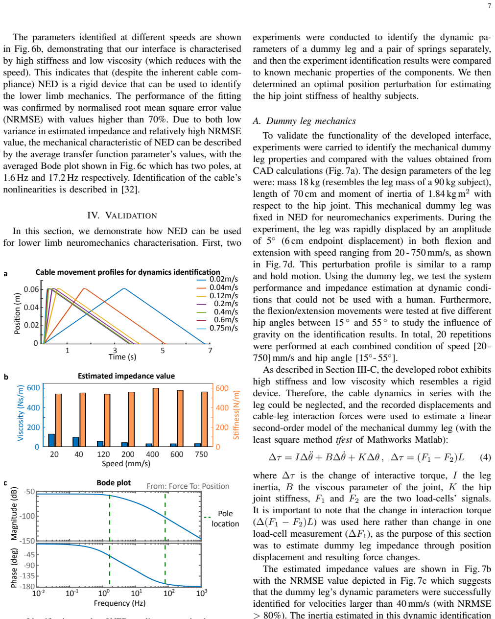
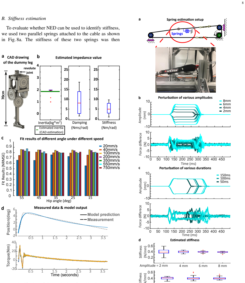
The core claim is that, once the cable dynamics in series with the leg are neglected, the leg's motion obeys a linear second-order joint model $\Delta\tau = I\Delta\ddot{\theta} + B\Delta\dot{\theta} + K\Delta\theta$, with $\Delta\tau = (F_1 - F_2)L$ read from two load cells, so a least-squares fit of a fast position perturbation returns the joint's inertia $I$, viscosity $B$, and stiffness $K$. Mechanical characterization shows the interface itself behaves as a stiff second-order system with stiffness above 500 N/m and low viscosity. Identification of a rigid dummy leg recovers its CAD-computed inertia of $1.84\,\mathrm{kg\,m^2}$, and spring tests recover known stiffness values, with accuracy improving at larger perturbation amplitudes. Applying the same perturbation on one relaxed human subject yields hip impedance estimates with small variance and inertia close to an anatomical prediction, supporting the claim that NED can identify single-joint neuromechanics in an upright posture without constraining the joint.
Load-bearing premise
The identification treats the cable transmission as effectively rigid and the leg as a rigid straight segment rotating in the sagittal plane, so the motor-side displacement is taken to equal the joint rotation; if the measured cable stiffness (around 500 N/m, comparable to the validation springs) cannot be neglected, the estimated joint stiffness would be biased.
Editorial extensions
If this is right
- One device can map hip, knee, and ankle neuromechanics by relocating pulleys and adjusting the seat, with the same actuator and control chain.
- A single perturbation protocol yields all three impedance parameters: stiffness from the plateau, inertia and viscosity from the transient fit.
- The interface supports isometric, isokinetic, and brief high-speed perturbations up to 750 mm/s, covering protocols used for reflex and spasticity assessment.
- Because body weight is carried by an independent structure and the joint is not mechanically fixed, measured mechanics correspond to upright, natural postures.
- Hip viscoelasticity, previously accessible mainly through less accurate multi-joint perturbations, can now be probed with a precise single-joint position displacement.
Reading between the lines
- A direct way to test the rigid-cable assumption is to include the identified cable stiffness as a series spring in the impedance model and see whether estimated joint stiffness changes by a detectable amount.
- Adding motion capture of the actual joint angle, rather than the motor encoder, would check the planar rigid-leg kinematic mapping and could extend the method to multi-joint perturbations.
- The same endpoint cable concept could scale to other joints or to patient populations, since the independent support removes the need for the subject to balance during measurement.
- The pilot compares only inertia to an anatomical model; a same-subject comparison of stiffness and viscosity against an independent method would confirm human accuracy.
Signed reviews
Editorial analysis
A structured set of objections, weighed in public.
Referee Report
Summary. The paper describes NED, a cable-driven endpoint-based robotic interface for identifying single-joint neuromechanics (inertia, viscosity, stiffness) of the hip, knee, and ankle in an upright, unconstrained posture. The authors characterize the device's kinematics, force measurement sensitivity, and cable transmission dynamics, then validate impedance identification on a rigid dummy leg (inertia compared with CAD) and on linear springs of known stiffness, and finally present a single-subject pilot for hip impedance. The central claim is that the device can accurately identify the mechanical impedance of a limb, with the identification model given in Eq. (4): Δτ = IΔθ¨ + BΔθ˙ + KΔθ.
Significance. If the accuracy claim holds, NED would be a useful addition to lower-limb neuromechanics research, because existing dynamometers constrain joints and exoskeletons have limited rigidity; the ability to test hip, knee, and ankle in a natural upright posture without joint constraints fills a practical gap. The paper provides careful mechanical characterization, multiple validation conditions including a dummy leg and springs, and a human pilot, which is more than many device papers offer. The validation targets are independent (CAD inertia, known spring constants, Winter's anatomical model), which is a strength. However, the central claim of accurate impedance identification rests on the assumption that the cable transmission is effectively rigid, and the manuscript's own cable identification data challenge that assumption. The result is therefore promising but not yet established.
major comments (3)
- [Section IV-A, Eq. (4)] The identification model Eq. (4) treats the motor-encoder displacement as the leg's angular displacement, neglecting the series cable compliance. The paper's own cable characterization in Section III-C reports a cable stiffness around 500 N/m (Fig. 6b) with poles at 1.6 and 17.2 Hz. This stiffness is the same order of magnitude as the spring constants validated in Section IV-B and, after conversion to a rotational stiffness for a ~0.7 m leg, is comparable to the joint impedances being estimated. With a series compliance Kx in series with the leg impedance, the stiffness seen by the motor is not the leg stiffness alone; for Kx = Ks, the apparent stiffness is halved. No independent measurement of the leg endpoint displacement (e.g., optical tracking) and no series-compliance correction are reported, so the quantitative accuracy claim in the abstract is not supported as it stands.
- [Section IV-B, Eq. (5)] The spring stiffness validation in Eq. (5) also uses motor-side displacement ΔX and measured force difference ΔF. If the spring is attached beyond the cable and the load-cells measure the cable tension, then the system identified includes the cable stiffness in series with the spring, and the motor-side stiffness is Kx*Ks/(Kx+Ks) rather than Ks. The paper does not state where the load-cells are located relative to the spring or the cable, does not report an independently measured spring constant, and does not compare motor displacement with spring endpoint displacement. Without these details, the claim that the estimated stiffness is 'similar to the spring constant' does not confirm that the device measures the spring's actual stiffness.
- [Section IV-C, Fig. 9] The human pilot applies the same rigid-transmission assumption when fitting Eq. (4) to motor-encoder data. The perturbation uses a 150 ms plateau, which contains spectral content near the 1.6 Hz cable pole identified in Section III-C. Since no motion capture or other endpoint measurement is used, the reported hip inertia, viscosity, and stiffness values may contain contributions from the cable dynamics. The small variance and the agreement of the inertia estimate with Winter's model are encouraging, but they do not resolve the transmission-identification confound. A definitive validation would require either endpoint motion measurement or inclusion of the identified cable dynamics in the identification model.
minor comments (4)
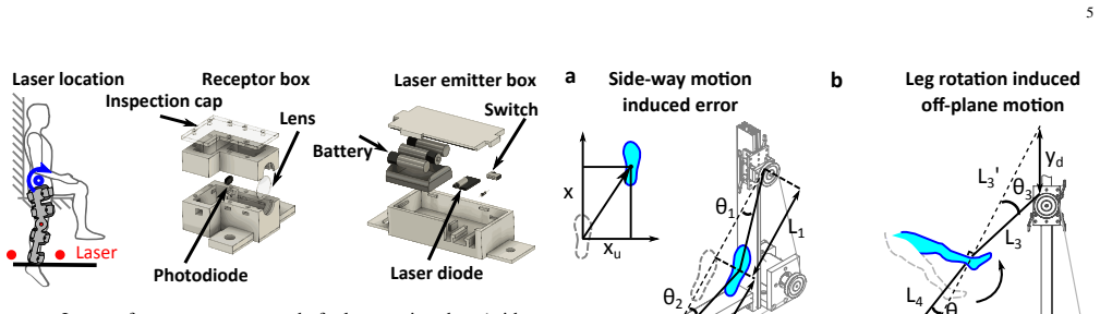
- [Section III-A, Eq. (2)] In Eq. (2), ρ_m is described as the motor pulley diameter, but the relation ˙x = ρ_m ˙θ_m is correct only if ρ_m is the pulley radius. Please clarify which quantity is used.
- [Section IV-C] The pilot subject is described as female, but the text later says 'asked to support his body weight' and 'his leg'; please make the pronouns consistent.
- [Section III-C, Fig. 6b] The identified cable stiffness values in Fig. 6b appear to vary considerably across speeds (roughly 0 to 600 N/m), yet the text states 'low variance' without reporting quantitative variance measures. Please provide error bars or confidence intervals for the identified parameters.
- [Section II-C] The text notes that adding a motion capture system 'would enable to measure hip joint rotations directly and could improve the leg displacement measurement relative to the current estimation from the motor encoder.' This is a relevant limitation of the current study and should be discussed explicitly in Section V, not only in the hardware description.
Circularity Check
No significant circularity: the impedance validations are checked against CAD, known springs, and the Winter anatomical model, not against the model's own fitted inputs.
full rationale
The paper's central claim that NED can identify single-joint neuromechanics accurately is validated against independent references rather than against its own fitted inputs. The dummy leg inertia estimate is compared to the CAD value of 1.84 kg m^2 (Fig. 7), the spring experiments use springs with known elasticity and compare the estimated stiffness to the known spring constants (Fig. 8 caption and results), and the human pilot's inertia estimate is compared to the anatomical model of Winter (Fig. 9b). The cable transmission is modeled as a second-order system (Eq. 3) from its own identification data, but this model is used only to justify neglecting series cable dynamics in Section IV-A; it does not define or constrain the limb impedance parameters fitted in Eq. (4). The stiffness estimation method of [33] is an externally published method, not an unverified self-citation, and the self-citations [32] and [34] provide design details and future application respectively rather than load-bearing evidence. The rigid-transmission assumption of Eq. (2) is a modeling assumption whose failure would bias estimates, but that is a correctness risk rather than a circular derivation. No equation is defined in terms of the target result, and no fitted parameter is renamed as a prediction.
Assumptions & free parameters
free parameters (2)
- Cable stiffness Kx =
~500 N/m (estimated using tfest)
- Cable viscosity Bx =
low, speed-dependent (Fig. 6b)
assumptions (5)
- standard math Capstan equation Tload = Thold * exp(mu*phi) holds for the cable-pulley contact (Eq. 1)
- domain assumption The leg is a rigid segment rotating in the sagittal plane about the hip, with the knee locked, so that motor speed relates to joint angular velocity by Eq. 2
- domain assumption The cable is perpendicular to the leg and the endpoint force is tangent to the leg's arc, so that joint torque equals (F1-F2)L
- ad hoc to paper The cable is effectively rigid: motor-encoder displacement equals leg endpoint displacement and cable dynamics can be neglected when estimating limb impedance
- domain assumption The subject is relaxed and does not produce voluntary reactions during the 150 ms perturbations, so the measured torque-angle relation reflects passive joint mechanics
Cite this review
Pith. "Pith review of Cable-driven robotic interface for lower limb neuromechanics identification." pith.science (2026). https://pith.science/paper/446H7VNI
@misc{pith2026190802689,
  author       = {Pith},
  title        = {Pith review of: Cable-driven robotic interface for lower limb neuromechanics identification},
  year         = {2026},
  howpublished = {\url{https://pith.science/paper/446H7VNI}},
  note         = {Machine review of arXiv:1908.02689}
}
read the original abstract
This paper presents a versatile cable-driven robotic interface to investigate the single-joint joint neuromechanics of the hip, knee and ankle. This endpoint-based interface offers highly dynamic interaction and accurate position control, as is typically required for neuromechanics identification. It can be used with the subject upright, corresponding to natural posture during walking or standing, and does not impose kinematic constraints on a joint, in contrast to existing interfaces. Mechanical evaluations demonstrated that the interface yields a rigidity above 500N/m with low viscosity. Tests with a rigid dummy leg and linear springs show that it can identify the mechanical impedance of a limb accurately. A smooth perturbation is developed and tested with a human subject, which can be used to estimate the hip neuromechanics.
Figures


Figures from the paper (5 more)

Reference graph
Works this paper leans on
-
[1]
Musculo-skeletal modelling of NMES-evoked knee extension in spinal cord injury,
P. J. Sinclair, G. M. Davis, and R. M. Smith, “Musculo-skeletal modelling of NMES-evoked knee extension in spinal cord injury,” Journal of Biomechanics , vol. 39, no. 3, pp. 483–92, 2006
2006
-
[2]
Knee and ankle joint torque-angle relationships of multi-joint leg extension,
D. Hahn, M. Olvermann, J. Richtberg, W. Seiberl, and A. Schwirtz, “Knee and ankle joint torque-angle relationships of multi-joint leg extension,” Journal of Biomechanics , vol. 44, no. 11, pp. 2059–65, 2011
work page 2011
-
[3]
Effects of spinal cord injury on lower-limb passive joint moments revealed through a nonlinear viscoelastic model
K. Amankwah, R. J. Triolo, and R. F. Kirsch, “Effects of spinal cord injury on lower-limb passive joint moments revealed through a nonlinear viscoelastic model.” Journal of Rehabilitation Research and Development , vol. 41, no. 1, pp. 15–32, 2004
2004
-
[4]
J. Dirnberger, H.-P. Wiesinger, A. K ¨osters, and E. M ¨uller, “Re- producibility for isometric and isokinetic maximum knee flexion and extension measurements using the IsoMed 2000-dynamometer,” Isokinetics and Exercise Science , vol. 20, no. 3, pp. 149–53, 2012
work page 2000
-
[5]
J. B. de Araujo Ribeiro Alvares, R. Rodrigues, R. de Azevedo Franke, B. G. C. da Silva, R. S. Pinto, M. A. Vaz, and B. M. Baroni, “Inter- machine reliability of the Biodex and Cybex isokinetic dynamometers for knee flexor/extensor isometric, concentric and eccentric tests,” Physical Therapy in Sport , vol. 16, no. 1, pp. 59–65, 2015
work page 2015
-
[6]
T. C. Valovich-mcLeod, S. J. Shultz, B. M. Gansneder, D. H. Perrin, and J. M. Drouin, “Reliability and validity of the Biodex system 3 pro isokinetic dynamometer velocity, torque and position measurements,” European Journal of Applied Physiology , vol. 91, no. 1, pp. 22–9, 2004
work page 2004
-
[7]
Clinical as- sessments performed during robotic rehabilitation by the gait training robot Lokomat,
L. L ¨unenburger, G. Colombo, R. Riener, and V . Dietz, “Clinical as- sessments performed during robotic rehabilitation by the gait training robot Lokomat,” in Proceedings of the IEEE International Conference on Rehabilitation Robotics , 2005, pp. 345–8
2005
-
[8]
Design and evaluation of the LOPES exoskeleton robot for interactive gait rehabilitation,
J. F. Veneman, R. Kruidhof, E. E. Hekman, R. Ekkelenkamp, E. H. Van Asseldonk, and H. Van Der Kooij, “Design and evaluation of the LOPES exoskeleton robot for interactive gait rehabilitation,” IEEE Transactions on Neural Systems and Rehabilitation Engineering , vol. 15, no. 3, pp. 379–86, sep 2007
work page 2007
Show all 34 references
-
[9]
Distinguishing active from passive components of ankle plantar flexor stiffness in stroke, spinal cord injury and multiple sclerosis,
J. Lorentzen, M. J. Grey, C. Crone, D. Mazevet, F. Biering-Sørensen, and J. B. Nielsen, “Distinguishing active from passive components of ankle plantar flexor stiffness in stroke, spinal cord injury and multiple sclerosis,” Clinical Neurophysiology , vol. 121, no. 11, pp. 1939–51, 2010
1939
-
[10]
Quantifying mus- cle tone in spinal cord injury patients using isokinetic dynamometric techniques
K. Perell, A. Scremin, O. Scremin, and C. Kunkel, “Quantifying mus- cle tone in spinal cord injury patients using isokinetic dynamometric techniques.” Paraplegia, vol. 34, no. 1, pp. 46–53, 1996
1996
-
[11]
Assessment of spasticity using isokinetic dynamometry in patients with spinal cord injury
M. N. Akman, R. Bengi, M. Karatas, S. Kilinc ¸, S. S ¨ozay, and R. Ozker, “Assessment of spasticity using isokinetic dynamometry in patients with spinal cord injury.” Spinal Cord , vol. 37, no. 9, pp. 638–43, 1999
1999
-
[12]
Differentiation between non-neural and neural contributors to ankle joint stiffness in cerebral 11 palsy,
K. L. De Gooijer-Van De Groep, E. De Vlugt, J. H. De Groot, H. C. Van Der Heijden-Maessen, D. H. Wielheesen, R. S. Van Wijlen- Hempel, J. H. Arendzen, and C. G. Meskers, “Differentiation between non-neural and neural contributors to ankle joint stiffness in cerebral 11 palsy,”...
2013
-
[13]
The validity and reliability of modelled neural and tissue properties of the ankle muscles in children with cerebral palsy,
L. H. Sloot, M. M. van der Krogt, K. L. d. G.-v. de Groep, S. van Eesbeek, J. de Groot, A. I. Buizer, C. Meskers, J. G. Becher, E. de Vlugt, and J. Harlaar, “The validity and reliability of modelled neural and tissue properties of the ankle muscles in children with cerebral pa...
2015
-
[14]
Test - retest reliability of cardinal plane isokinetic hip torque and EMG,
T. L. Claiborne, M. K. Timmons, and D. M. Pincivero, “Test - retest reliability of cardinal plane isokinetic hip torque and EMG,” Journal of Electromyography and Kinesiology , vol. 19, no. 5, pp. e345–52, 2009
2009
-
[15]
Design of a cable-driven active leg exoskeleton (C-ALEX) and gait training experiments with human subjects,
X. Jin, X. Cui, and S. K. Agrawal, “Design of a cable-driven active leg exoskeleton (C-ALEX) and gait training experiments with human subjects,” in Proceedings of the IEEE International Conference on Robotics and Automation (ICRA) , 2015, pp. 5578–5583
2015
-
[16]
TWIICE - A lightweight lower-limb exoskeleton for complete paraplegics,
T. V ouga, R. Baud, J. Fasola, M. Bouri, and H. Bleuler, “TWIICE - A lightweight lower-limb exoskeleton for complete paraplegics,” in IEEE International Conference on Rehabilitation Robotics . IEEE Computer Society, aug 2017, pp. 1639–1645
2017
-
[17]
Estima- tion of human hip and knee multi-joint dynamics using the LOPES gait trainer,
B. Koopman, E. H. F. van Asseldonk, and H. van der Kooij, “Estima- tion of human hip and knee multi-joint dynamics using the LOPES gait trainer,” IEEE Transactions on Robotics , vol. 32, no. 4, pp. 920– 32, 2016
2016
-
[18]
Intrinsic and reflex contributions to human ankle stiffness: variation with activation level and position,
M. Mirbagheri, H. Barbeau, and R. Kearney, “Intrinsic and reflex contributions to human ankle stiffness: variation with activation level and position,” Experimental Brain Research, vol. 135, no. 4, pp. 423– 36, 2000
2000
-
[19]
Intrinsic and reflex stiffness in normal and spastic, spinal cord injured subjects,
M. Mirbagheri, H. Barbeau, M. Ladouceur, and R. Kearney, “Intrinsic and reflex stiffness in normal and spastic, spinal cord injured subjects,” Experimental Brain Research , vol. 141, no. 4, pp. 446–59, 2001
2001
-
[20]
Estimation of human ankle impedance during the stance phase of walking,
E. J. Rouse, L. J. Hargrove, E. J. Perreault, and T. A. Kuiken, “Estimation of human ankle impedance during the stance phase of walking,” IEEE Transactions on Neural Systems and Rehabilitation Engineering, vol. 22, no. 4, pp. 870–8, 2014
2014
-
[21]
Biomechanic changes in passive properties of hemiplegic ankles with spastic hypertonia,
S. G. Chung, E. Van Rey, Z. Bai, E. J. Roth, and L. Q. Zhang, “Biomechanic changes in passive properties of hemiplegic ankles with spastic hypertonia,” Archives of Physical Medicine and Rehabilitation , vol. 85, no. 10, pp. 1638–46, 2004
2004
-
[22]
Ankle Mechanical Impedance During the Stance Phase of Running,
A. L. Shorter and E. J. Rouse, “Ankle Mechanical Impedance During the Stance Phase of Running,” IEEE Transactions on Biomedical Engineering, sep 2019
2019
-
[23]
Estimations of relative effort during sit-to-stand increase when accounting for variations in maximum voluntary torque with joint angle and angular velocity,
K. A. Bieryla, D. E. Anderson, and M. L. Madigan, “Estimations of relative effort during sit-to-stand increase when accounting for variations in maximum voluntary torque with joint angle and angular velocity,” Journal of Electromyography and Kinesiology , vol. 19, no. 1, pp. 1...
2009
-
[24]
Concentric and eccentric isokinetic knee extension: A reproducibility study using the IsoMed 2000-dynamometer,
J. Dirnberger, A. K ¨osters, and E. M ¨uller, “Concentric and eccentric isokinetic knee extension: A reproducibility study using the IsoMed 2000-dynamometer,” Isokinetics and Exercise Science , vol. 20, no. 1, pp. 31–5, 2012
2000
-
[25]
LOPES II - Design and evaluation of an admittance controlled gait training robot with shadow-leg approach,
J. Meuleman, E. Van Asseldonk, G. Van Oort, H. Rietman, and H. Van Der Kooij, “LOPES II - Design and evaluation of an admittance controlled gait training robot with shadow-leg approach,” IEEE Trans- actions on Neural Systems and Rehabilitation Engineering , vol. 24, no. 3, pp....
2016
-
[26]
A study of lower-limb mechanics during stair-climbing
T. P. Andriacchi, G. B. Andersson, R. W. Fermier, D. Stern, and J. O. Galante, “A study of lower-limb mechanics during stair-climbing.” The Journal of Bone and Joint Surgery. American volume , vol. 62, no. 5, pp. 749–57, 1980
1980
-
[27]
The force-velocity relationship of paralyzed quadriceps muscles during functional elec- trical stimulation cycling,
C. Fornusek, P. J. Sinclair, and G. M. Davis, “The force-velocity relationship of paralyzed quadriceps muscles during functional elec- trical stimulation cycling,”Neuromodulation, vol. 10, no. 1, pp. 68–75, 2007
2007
-
[28]
D. A. Winter, Biomechanics and motor control of human movement . Wiley, 2009
2009
-
[29]
A robot and control algorithm that can synchronously assist in naturalistic motion during body-weight-supported gait training following neurologic injury,
D. Aoyagi, W. Ichinose, S. Harkema, D. Reinkensmeyer, and J. Bo- brow, “A robot and control algorithm that can synchronously assist in naturalistic motion during body-weight-supported gait training following neurologic injury,” IEEE Transactions on Neural Systems and Rehabilit...
2007
-
[30]
A muscle tension esti- mation method by using mechanical impedance of human knee joint during training by manipulator,
A. Fujii, S. Oda, S. Komada, and J. Hirai, “A muscle tension esti- mation method by using mechanical impedance of human knee joint during training by manipulator,” in Mechatronics,IEEE International Conference on Mechatronics . IEEE, 2007, pp. 1–6
2007
-
[31]
The effect of transmission design on force- controlled manipulator performance,
W. T. Townsend, “The effect of transmission design on force- controlled manipulator performance,” Ph.D. dissertation, Mas- sachusetts Institute of Technology, USA, 1988
1988
-
[32]
Development of the neuromechanics evaluation device (NED) for subject-specific lower limb modelling of spinal cord injury,
H.-Y . Huang, “Development of the neuromechanics evaluation device (NED) for subject-specific lower limb modelling of spinal cord injury,” Ph.D. dissertation, Imperial College of Science, Technology and Medicine, London, UK, 2019
2019
-
[33]
A method for measuring endpoint stiffness during multi- joint arm movements
E. Burdet, R. Osu, D. W. Franklin, T. Yoshioka, T. E. Milner, and M. Kawato, “A method for measuring endpoint stiffness during multi- joint arm movements.” Journal of Biomechanics , vol. 33, no. 12, pp. 1705–9, 2000
2000
-
[34]
The influence of posture, applied force and perturbation direction on hip joint viscoelasticity,
H.-Y . Huang, A. Arami, I. Farkhatdinov, D. Formica, and E. Burdet, “The influence of posture, applied force and perturbation direction on hip joint viscoelasticity,” IEEE Transactions on Neural Systems and Rehabilitation Engineering , 2020
2020
Reviewed August 14, 2026 · model on record in the stance chip above.
Discussion (0). Continue with ORCID to comment.