REVIEW 4 major objections 7 minor 29 references
Loss Minimization with Optimal Power Dispatch in Multi-Frequency HVac Power Systems
T0 review · 4 major / 7 minor · reviewed 2026-08-14 · deepseek-v4-flash
Pith's one-line read This paper claims that a multi-period optimal power flow dispatching generators, shunt capacitors, and back-to-back converters together cuts peak-load losses in a multi-frequency HVac system from 4.86% to 1.84% and eliminates voltage…
desk verdict First multi-frequency HVac OPF with real exact-Hessian content; headline loss numbers hinge on an internally inconsistent converter loss model. read the letter →
The pith
A machine-rendered reading of the paper's core claim, the machinery that carries it, and where it could break.
The reading
What carries the argument
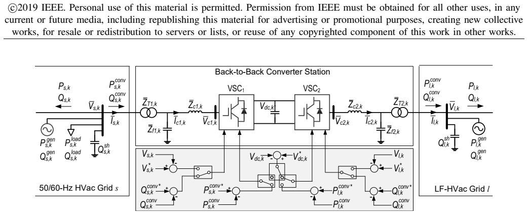
The load-bearing mechanism is the multi-period OPF in rectangular coordinates: bus voltages are split into real and imaginary parts so the Hessian matrices of the nodal power-balance equalities become constant and can be precomputed once in compressed sparse-row storage, while discrete capacitor dispatches are forced to their nearest allowed values by a quadratic penalty inside a predictor-corrector primal-dual interior-point method. A back-to-back converter station is modeled as two voltage-source converters sharing a dc link, with Joule losses in transformers and phase reactors plus a switching-loss polynomial $a_0 + a_1 I + a_2 I^2$; that loss model enters the OPF as a power-balance equality whose exact Jacobian and Hessian are derived in the appendix. This combination makes a nonconvex mixed-integer nonlinear program solvable in about one second per time step on the test system.
What would settle it
Run the same multi-period OPF with switching-loss coefficients measured from the actual converters instead of the assumed values in Table I; if the optimal dispatch or the 1.84% peak-loss figure changes materially, the claimed loss reduction rests on the unmeasured assumption.
Extended reading notes
Core claim
The central claim is that optimal dispatch of generators, shunt capacitors, and back-to-back converters in a multi-frequency HVac transmission system is a solvable, multi-period MINLP whose solution substantially reduces losses. In the tested system, the optimizer cuts losses from 4.86% to 1.84% at peak load and eliminates voltage violations throughout a simulated day, while also reducing capacitor switching operations when that is penalized. The paper argues the key enabler is writing the OPF in rectangular coordinates, where the Hessians of nodal power balance constraints are constant and can be precomputed in compressed sparse-row form, and deriving the exact Hessians of the converter power-balance and capability constraints. The resulting predictor-corrector interior-point framework converges to discrete capacitor settings and matches the solution quality of a general mixed-integer solver with fewer iterations.
Load-bearing premise
Every back-to-back converter in the study is assumed to have the same switching-loss polynomial, with coefficients taken from prior references rather than measured for the actual hardware, and both the loss objective and the converter dispatch depend on that model.
Editorial extensions
If this is right
- In a multi-frequency HVac system, back-to-back converters are not just frequency couplers; their active and reactive dispatch can be co-optimized with generators and capacitors to cut system losses.
- The proposed OPF keeps load-bus voltages within limits across the daily load profile, eliminating the overvoltages observed under arbitrary dispatch.
- Penalizing capacitor switching in the objective reduces both switching operations and losses, meaning converter dispatch can substitute for capacitor-bank action.
- The rectangular-coordinate formulation with precomputed constant Hessians makes each time step fast enough (about one second) for operational use on systems of this size.
- The exact Hessian expressions for converter constraints can be reused in OPF formulations for hybrid HVac-HVdc systems, as the appendix notes.
Reading between the lines
- If the loss model is accurate, the same OPF could be used in planning: the marginal loss value at each converter site would rank candidate LF-HVac corridors by energy savings.
- The reported 1.84% peak-loss figure assumes the switching-loss coefficients in Table I are identical across converters; a sensitivity sweep over plausible coefficient ranges would reveal how much of the reduction is an artifact of that assumption.
- Because the formulation treats the LF-HVac grid as load-free, extending it to serve loads inside the low-frequency grid could change both the optimum and the converter dispatch, a natural next step not explored in the paper.
- The same warm-started interior-point machinery could be adapted to a rolling-horizon online dispatch, using the previous time step's solution to track load changes faster than the reported one-second solve.
Signed reviews
Editorial analysis
A structured set of objections, weighed in public.
Referee Report
Summary. This paper proposes a multi-period optimal power flow (OPF) for a multi-frequency HVac system in which a conventional 50/60-Hz grid and a low-frequency HVac grid are interconnected by back-to-back VSC converters. The decision variables are generator dispatches, shunt-capacitor steps, and converter active/reactive set points; the objective minimizes weighted generation (equivalently losses) plus a capacitor-switching penalty, subject to ac network constraints, converter loss balance, and converter capability limits. The resulting mixed-integer nonlinear program is solved by a predictor-corrector primal-dual interior-point method with a penalty-based rounding scheme for the discrete capacitor variables. On a 57-bus/8-bus multi-frequency test system, the paper reports peak-load losses of 4.86% under an arbitrary dispatch, 2.59% with OPF on generators and capacitors, and 1.84% when converters are also optimized, with voltage violations eliminated. The solver is compared against IPOPT and BONMIN on two test systems.
Significance. If the quantitative claims hold, the paper provides a useful, clearly specified OPF model for an emerging transmission technology, and the solution method is a reasonable extension of PCPDIPM to MINLP with discrete shunt elements. The use of rectangular coordinates with precomputed constant Hessians for network constraints is a practical efficiency idea, and the comparison with IPOPT and BONMIN gives external grounding for the solution quality. The main value is the complete formulation (converter losses, capability curves, multi-period capacitor switching) rather than a fundamentally new algorithm. However, the headline loss-reduction numbers depend on assumed converter loss coefficients and on the correctness of the published Hessian formulas, so the quantitative claims are not yet fully established.
major comments (4)
- [§IV-E, Eq. (16), Table I] Table I lists different a2 values for rectifier (4.400×10^-3) and inverter (6.667×10^-3) modes, but Eq. (16) uses a single a2 for both VSC1 and VSC2 sides of the back-to-back converter. In the operating point of Table III, P_conv_s is negative and P_conv_l is positive for every converter, so VSC1 and VSC2 operate in different modes; applying one a2 is therefore internally ambiguous. Because converter losses appear in the power-balance constraint that couples the two sides, this ambiguity can change the optimal converter dispatch and the reported 1.84% peak loss. Please introduce separate a2,rect and a2,inv (or state explicitly that the same value is used for both modes and justify it).
- [§VI-B, Figs. 7-8] The converter loss coefficients in Table I are assumed identical for all five converters, even though Converters A and B have Srated = 300 MVA while C-E have Srated = 200 MVA, and the coefficients are taken from previous VSC-HVDC literature rather than measured or fitted for these converters. Since the OPF can trade off line losses against converter losses, the optimal dispatch—and hence the 4.86% to 1.84% reduction and the Case 2 vs Case 3 ranking—is sensitive to this assumed loss curve. A sensitivity study over a0, a1, and a2 (e.g., ±20% and mode-dependent variation) is needed to establish the robustness of the headline result; without it, the central quantitative claim is not supported at the reported precision.
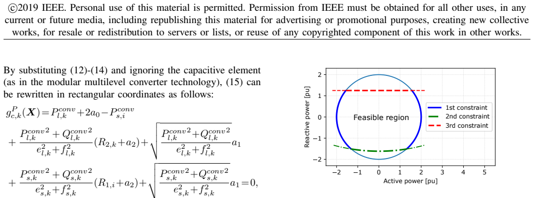
- [Appendix] The Appendix contains algebraic errors in the claimed exact Hessian matrices. For constraint (16), the a1 terms should scale as |S| (for voltage derivatives) and as |S|^-3 (for P/Q derivatives), but the printed formulas use |S|^2 and |S|^-6; e.g., ∂2g/∂P^2 should be 2(R+a2)/V^2 + a1 Q^2/(V |S|^3), not with |S|^6 in the denominator. For constraint (18), the voltage second derivative has the wrong sign: hIconv = P^2+Q^2-(Imax)^2(e^2+f^2), so ∂2h/∂e^2 = -2(Imax)^2, not +2(Imax)^2. For constraint (20), the e-derivative should have a b-term Q+b(3e^2+f^2) and a separate -2k_V^2 term, not the printed Q+b(e^2+3f^2)-2k_V^2 inside the 4b factor; the f-derivative has a similar swap, and constraint (21), which has opposite signs on the g and b terms, requires its own formulas that are not given. Because the exact Hessians are a stated contribution and are used to justify the solver's efficiency, these errors must be corrected.
- [§V, Table V] The penalty-based rounding of shunt capacitors to discrete values is introduced without a feasibility or optimality guarantee. The comparison with BONMIN in Table V covers only two test systems and reports only objective values and iteration counts; it does not demonstrate that the final discrete solution satisfies all constraints or that the penalty heuristic reaches the same feasible set as BONMIN. Please either provide a formal statement of the conditions under which the rounding step preserves feasibility/optimality, or explicitly label the method as heuristic and add a post-hoc constraint-violation check for the reported solutions.
minor comments (7)
- [§IV-E, Eq. (16)] The subscripts i and k are mixed in Eq. (16) (P_conv_s,i, R1,i) for the same converter; use k consistently.
- [§VI-B] Case 1 is described only as 'a given power dispatch'; please specify the generator, shunt, and converter set points so the 4.86% baseline is reproducible.
- [§VI-C, Table V] Table V would be more informative if it reported feasibility tolerances and the discrete feasibility of the IPOPT solution, since IPOPT solves the continuous relaxation only.
- [§VII] The conclusion's '3% loss reduction' should be stated as '3.02 percentage points' (4.86% to 1.84%) to avoid misinterpretation.
- [§VI-B, Table III] The text mentions 'red numbers' in Table III, but no red numbers are visible in the printed table; clarify which entries are binding.
- [§VI-B] The choice α2 = 0.2 in Case 3 is not justified; a brief sensitivity discussion would help the reader understand the loss-versus-switching trade-off.
- [§II] The claim that 'no research has been done to solve OPF in multi-frequency HVac power systems' is difficult to verify; consider softening to 'to the best of our knowledge' and citing adjacent HVDC/multi-frequency OPF works.
Circularity Check
No circularity: the loss-reduction numbers are outputs of an optimization against a self-contained model, with converter-loss coefficients taken from external references and the solver cross-checked against independent solvers.
full rationale
The paper's central derivation chain is: formulate a multi-period OPF (objective Eq. 2, constraints Eqs. 3-22), solve it with a modified PCPDIPM, and compare the resulting optimized losses with an arbitrary-dispatch power-flow baseline (Case 1). The headline 4.86%-to-1.84% loss reduction is the minimized objective value, not a fitted or pre-imposed quantity. The converter switching-loss coefficients in Table I are taken from external references [11], [25] and are not estimated from the test system, so the prediction is not statistically forced by its inputs. The authors' own prior PF tool [10] is used only to generate the Case 1 baseline and warm starts; the central OPF solution is independently grounded by cross-checking against IPOPT and BONMIN in Table V, where the objective values closely match (1,505.84, 1,505.97, and 1,505.17 MW). Thus the result does not reduce to a self-citation chain or to a definition. The noted weaknesses (identical switching-loss coefficients assumed for all converters, and the rectifier/inverter a2 ambiguity between Table I and Eq. 16) are modeling-accuracy or correctness concerns, not circularity: they do not make the output equivalent to the input by construction.
Assumptions & free parameters
free parameters (1)
- alpha2 (weighting coefficient for capacitor switching penalty) =
0.0 in Case 2, 0.2 in Case 3
assumptions (5)
- domain assumption The LF-HVac grid does not serve any loads.
- domain assumption BTB VSC converters are modeled as controllable voltage sources behind impedance with no harmonics.
- domain assumption Switching losses follow a0 + a1*I + a2*I^2 with coefficients from Table I, identical across converters.
- domain assumption The modular multilevel converter has no shunt capacitive branch, so simplified converter constraints (16), (18), (20), (21) apply.
- ad hoc to paper The penalty-based rounding of discrete shunt capacitor variables yields a feasible discrete solution in the nonconvex MINLP.
Cite this review
Pith. "Pith review of Loss Minimization with Optimal Power Dispatch in Multi-Frequency HVac Power Systems." pith.science (2026). https://pith.science/paper/RHQ75CAL
@misc{pith2026190802832,
  author       = {Pith},
  title        = {Pith review of: Loss Minimization with Optimal Power Dispatch in Multi-Frequency HVac Power Systems},
  year         = {2026},
  howpublished = {\url{https://pith.science/paper/RHQ75CAL}},
  note         = {Machine review of arXiv:1908.02832}
}
read the original abstract
Low-frequency high voltage ac transmission scheme has recently been proposed as an alternative approach for bulk power transmission. This paper proposes a multi-period optimal power flow (OPF) for a multi-frequency HVac transmission system that interconnects both conventional 50/60-Hz and low-frequency grids using back-to-back converters with a centralized control scheme. The OPF objective is to minimize system losses by determining the optimal dispatch for generators, shunt capacitors, and converters. The OPF constraints include the operational constraints of all HVac grid and converter stations. The resulting mixed-integer nonlinear programing problem is solved using a proposed framework based on the predictor-corrector primal-dual interior-point method. The proposed OPF formulation and solution approach are verified using a multi-frequency HVac transmission system that is modified from the IEEE 57-bus system. The results with the optimal dispatch from the proposed method during a simulated day show a significant loss reduction and an improved voltage regulation compared to those when an arbitrary dispatch is chosen.
Figures

Figures from the paper (7 more)


Reference graph
Works this paper leans on
-
[1]
Feasibility of the low frequency AC transmission,
T. Funaki and K. Matsuura, “Feasibility of the low frequency AC transmission,” in Power Engineering Society Winter Meeting, 2000. IEEE, vol. 4, 2000, pp. 2693–2698 vol.4
2000
-
[2]
Low frequency high voltage offshore grid for transmission of renewable power,
W. Fischer, R. Braun, and I. Erlich, “Low frequency high voltage offshore grid for transmission of renewable power,” in 2012 3rd IEEE PES Innovative Smart Grid Technologies Europe (ISGT Europe) , Oct 2012, pp. 1–6
work page 2012
-
[3]
Low frequency transmission,
“Low frequency transmission,” PSERC Publication, Tech. Rep., 2012
2012
-
[4]
Steady-state analysis and perfor- mance of low frequency ac transmission lines,
T. Ngo, M. Lwin, and S. Santoso, “Steady-state analysis and perfor- mance of low frequency ac transmission lines,” IEEE Transactions on Power Systems, vol. 31, no. 5, pp. 3873–3880, Sept 2016
2016
-
[5]
V oltage stability of low frequency ac transmission systems,
T. Ngo, Q. Nguyen, and S. Santoso, “V oltage stability of low frequency ac transmission systems,” in 2016 IEEE/PES Transmission and Distri- bution Conference and Exposition (TnD) , May 2016, pp. 1–5
work page 2016
-
[6]
D. Rosewater, Q. Nguyen, and S. Santoso, “Optimal field voltage and energy storage control for stabilizing synchronous generators on flexible ac transmission systems,” in 2018 IEEE/PES Transmission and Distribution Conference and Exposition (T D) , April 2018, pp. 1–9. 9 c©2019 IEEE. Personal use of this material is permitted. Permission from IEEE must be o...
work page 2018
-
[7]
ScottishPower Renewables Investigates low frequency transmission for EA3,
T. Russell, “ScottishPower Renewables Investigates low frequency transmission for EA3,” https://www .4coffshore.com/windfarms/ scottishpower-renewables-investigates-low-frequency-transmission-for- ea3-nid4661.html, Tech. Rep., 2016
work page 2016
-
[8]
Low frequency ac for offshore wind power transmission - prospects and challenges,
I. Erlich, F. Shewarega, H. Wrede, and W. Fischer, “Low frequency ac for offshore wind power transmission - prospects and challenges,” in 11th IET International Conference on AC and DC Power Transmission , Feb 2015, pp. 1–7
2015
Show all 29 references
-
[9]
Design of vsc connected low frequency ac offshore transmission with long hvac cables,
J. Ruddy, R. Meere, C. OLoughlin, and T. ODonnell, “Design of vsc connected low frequency ac offshore transmission with long hvac cables,” IEEE Transactions on Power Delivery , vol. 33, no. 2, pp. 960– 970, April 2018
2018
-
[10]
Power flow in a multi- frequency hvac and hvdc system: Formulation, solution, and validation,
Q. Nguyen, G. Todeschini, and S. Santoso, “Power flow in a multi- frequency hvac and hvdc system: Formulation, solution, and validation,” IEEE Transactions on Power Systems , vol. 34, no. 4, pp. 2487–2497, July 2019
2019
-
[11]
Generalized steady-state VSC MTDC model for sequential AC/DC power flow algorithms,
J. Beerten, S. Cole, and R. Belmans, “Generalized steady-state VSC MTDC model for sequential AC/DC power flow algorithms,” IEEE Transactions on Power Systems , vol. 27, no. 2, pp. 821–829, May 2012
2012
-
[12]
A multi-option unified power flow approach for hybrid AC/DC grids incorporating multi-terminal VSC- HVDC,
M. Baradar and M. Ghandhari, “A multi-option unified power flow approach for hybrid AC/DC grids incorporating multi-terminal VSC- HVDC,” IEEE Transactions on Power Systems, vol. 28, no. 3, Aug 2013
2013
-
[13]
Power flow solution for multi- frequency AC and multi-terminal HVDC power systems,
Q. Nguyen, T. Ngo, and S. Santoso, “Power flow solution for multi- frequency AC and multi-terminal HVDC power systems,” in 2016 IEEE Power and Energy Society General Meeting (PESGM) , July 2016, pp. 1–5
2016
-
[14]
Branch flow model: Relaxations and convexificationpart i,
M. Farivar and S. H. Low, “Branch flow model: Relaxations and convexificationpart i,” IEEE Transactions on Power Systems , vol. 28, no. 3, pp. 2554–2564, Aug 2013
2013
-
[15]
Zero duality gap in optimal power flow problem,
J. Lavaei and S. H. Low, “Zero duality gap in optimal power flow problem,” IEEE Transactions on Power Systems , vol. 27, no. 1, pp. 92–107, Feb 2012
2012
-
[16]
Critical review of recent advances and further devel- opments needed in ac optimal power flow,
F. Capitanescu, “Critical review of recent advances and further devel- opments needed in ac optimal power flow,” Electric Power Systems Research, vol. 136, 2016
2016
-
[17]
An interior-point method for non- linear optimal power flow using voltage rectangular coordinates,
G. L. Torres and V . H. Quintana, “An interior-point method for non- linear optimal power flow using voltage rectangular coordinates,” IEEE Transactions on Power Systems , vol. 13, no. 4, Nov 1998
1998
-
[18]
An extended nonlinear primal-dual interior-point algorithm for reactive-power optimization of large-scale power systems with discrete control variables,
M. Liu, S. K. Tso, and Y . Cheng, “An extended nonlinear primal-dual interior-point algorithm for reactive-power optimization of large-scale power systems with discrete control variables,” IEEE Transactions on Power Systems, vol. 17, no. 4, pp. 982–991, Nov 2002
2002
-
[19]
Exact optimal power dispatch in unbalanced distribution systems with high pv penetration,
Q. Nguyen, H. V . Padullaparti, K. Lao, S. Santoso, X. Ke, and N. Samaan, “Exact optimal power dispatch in unbalanced distribution systems with high pv penetration,”IEEE Transactions on Power Systems, vol. 34, no. 1, pp. 718–728, Jan 2019
2019
-
[20]
On the implementation of an interior-point filter line-search algorithm for large-scale nonlinear programming,
A. W ¨achter and L. T. Biegler, “On the implementation of an interior-point filter line-search algorithm for large-scale nonlinear programming,” Mathematical Programming, vol. 106, no. 1, pp. 25–57,
-
[21]
R. H. Byrd, J. Nocedal, and R. A. Waltz, Knitro: An Integrated Package for Nonlinear Optimization . Boston, MA: Springer US, 2006, pp. 35–59. [Online]. Available: https://doi .org/10.1007/0-387-30065-1 4
2006 doi
-
[22]
An algorithmic framework for convex mixed integer nonlinear programs,
P. Bonami, L. T. Biegler, A. R. Conn, G. Cornujols, I. E. Grossmann, C. D. Laird, J. Lee, A. Lodi, F. Margot, N. Sawaya, and A. Wchter, “An algorithmic framework for convex mixed integer nonlinear programs,” Discrete Optimization , vol. 5, no. 2, pp. 186 – 204, 2008, in Memory...
2008
-
[23]
Teodorescu, M
R. Teodorescu, M. Liserre, and P. Rodrguez, Grid converters for photovoltaic and wind power systems . John Wiley, Ltd, 2011
2011
-
[24]
Control of HVDC light system using conventional and direct current vector control approaches,
S. Li, T. A. Haskew, and L. Xu, “Control of HVDC light system using conventional and direct current vector control approaches,” IEEE Transactions on Power Electronics , vol. 25, no. 12, Dec 2010
2010
-
[25]
A sequential AC/DC power flow algorithm for networks containing multi-terminal VSC HVDC systems,
J. Beerten, R. Belmans, and S. Cole, “A sequential AC/DC power flow algorithm for networks containing multi-terminal VSC HVDC systems,” in IEEE PES General Meeting , July 2010, pp. 1–7
2010
-
[26]
A new approach for benefit evaluation of multiterminal VSC HVDC using a proposed mixed AC-DC optimal power flow,
W. Feng, L. A. Tuan, L. B. Tjernberg, A. Mannikoff, and A. Bergman, “A new approach for benefit evaluation of multiterminal VSC HVDC using a proposed mixed AC-DC optimal power flow,”IEEE Transactions on Power Delivery , vol. 29, no. 1, pp. 432–443, Feb 2014
2014
-
[27]
It is time to connect with offshore wind supplement,
ABB, “It is time to connect with offshore wind supplement,” https://library.e.abb.com/public/1bad1970cd0766eec1257b28005757df/ Pow0038%20R6%20LR.pdf, Tech. Rep., 2010
2010
-
[28]
[Online]
Literature-based power flow test cases. [Online]. Available: http: //icseg.iti.illinois.edu/power-cases/ Quan Nguyen (S’15) is currently pursuing a PhD at The University of Texas at Austin. His research interests are power system control and optimization, renewable energy integ...
-
[2006]
Available: http://dx.doi.org/10.1007/s10107-004-0559-y
[Online]. Available: http://dx.doi.org/10.1007/s10107-004-0559-y
Reviewed August 14, 2026 · model on record in the stance chip above.
Discussion (0). Continue with ORCID to comment.