REVIEW 3 major objections 5 minor 28 references
Fast longitudinal beam dynamics optimization in x-ray FEL linear accelerators
T0 review · 3 major / 5 minor · reviewed 2026-08-14 · deepseek-v4-flash
Pith's one-line read A lumped one-dimensional longitudinal beam dynamics model, embedded in a multi-objective differential evolution optimizer, finds LCLS-II linac settings with core peak current above 1.2 kA, about 50% higher than the design baseline.
desk verdict Fast lumped 1D longitudinal model with collective effects is a genuinely useful optimization tool, but the headline 50% peak-current gain is read from the 1D model and not confirmed by a numerical 3D value. read the letter →
The pith
A machine-rendered reading of the paper's core claim, the machinery that carries it, and where it could break.
The reading
What carries the argument
The load-bearing object is the lumped one-dimensional longitudinal beam dynamics model. Each macroparticle carries $(z,\Delta\gamma)$ and a charge weight; RF sections are collapsed to a single accelerating element with a phase-dependent energy kick, and bunch compressors become a thin-lens map with $R_{56}\approx 2\theta^2(L_{db}+\frac{2}{3}L_b)$, $T_{566}\approx -\frac{3}{2}R_{56}$, and $U_{5666}\approx 2R_{56}$. All collective forces enter as convolutions evaluated by FFT, and CSR is applied through the last dipole of each chicane using the integrated transient and steady-state wake functions given in Section II; the paper also notes a 0.5% upward calibration of $R_{56}$ to match the 3D code's current profile. This machinery converts a few hundred slice macroparticles into a near-instant objective-function evaluation, making an ~76,000-evaluation Pareto search feasible in 1.5 hours on 64 cores.
What would settle it
Run the optimized settings through a fully 3D element-by-element simulation with the measured injector slice energy spread and report the peak current in the same $\pm5\,\mu\mathrm{m}$ core window; if it comes out well below 1.2 kA, the claimed improvement would not survive. A complementary check is to measure the bunch current or FEL gain at the undulator entrance on the real machine with those settings.
Extended reading notes
Core claim
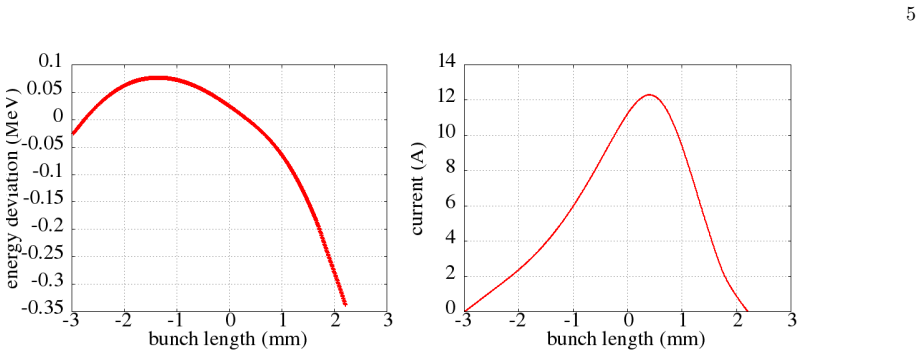
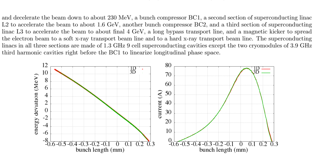
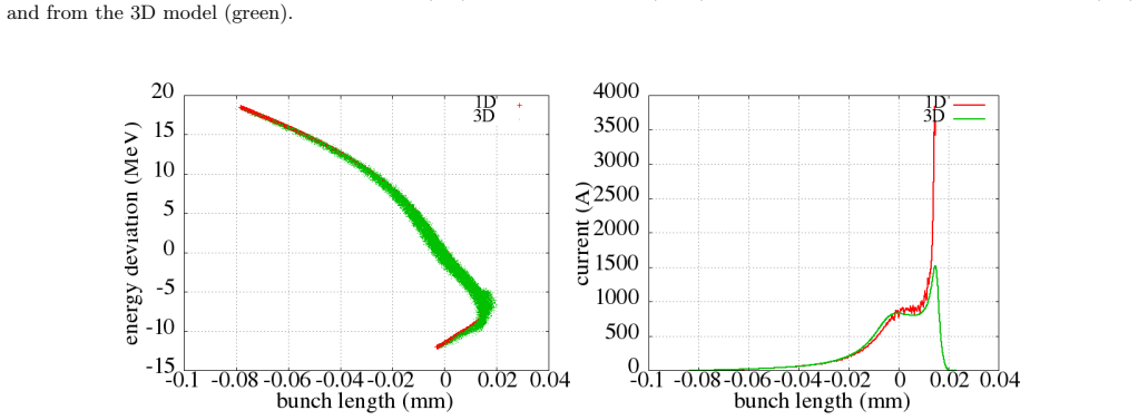
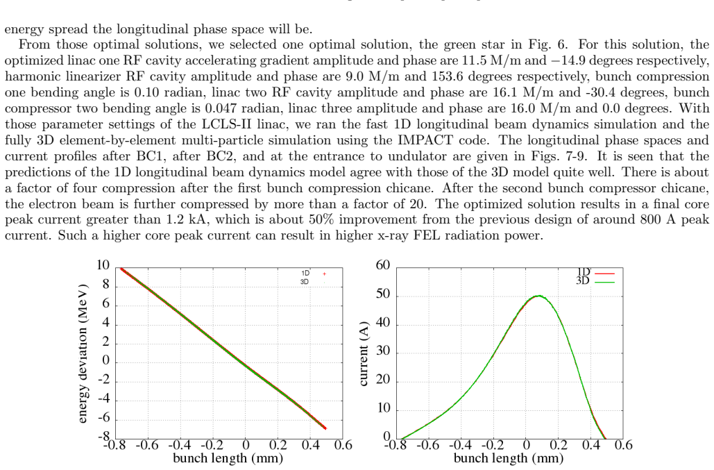
On its own terms, the paper establishes that longitudinal dynamics through a modern superconducting linac can be captured by a small set of lumped elements: one RF kick per accelerating section, a thin-lens magnetic chicane with $R_{56}$, $T_{566}$, and $U_{5666}$ terms, and FFT-convolved wakes for space charge, structure, resistive wall, and CSR, using only a few hundred to a thousand weighted macroparticles. With this model, the paper finds a multi-objective optimum for LCLS-II with 10 control parameters where the core peak current rises from ~800 A to above 1.2 kA, while the rms energy spread in the chosen $\pm5\,\mu\mathrm{m}$, $\pm8\,\mathrm{MeV}$ window is minimized along the Pareto front. The paper reports that at the selected optimal setting the 1D model's longitudinal phase space and current profile agree qualitatively with full 3D multi-particle simulations after both bunch compressors and at the undulator entrance.
Load-bearing premise
The 1.2 kA prediction relies on each longitudinal slice starting with zero internal energy spread, while the 3D comparison shown is visual rather than a measured peak-current number, so real slice energy spread at the optimized settings could reduce the claimed 50% gain.
Editorial extensions
If this is right
- If the lumped model is as faithful as the Section II benchmarks indicate, linac designers can replace expensive element-by-element searches with this fast surrogate, enabling scans over more parameters and more objectives.
- The reported >1.2 kA core current at the selected Pareto point implies higher x-ray FEL radiation power for the same LCLS-II hardware, provided the 1D prediction survives a quantitative 3D peak-current check.
- The method turns longitudinal design into a compact control-parameter optimization, so it can be re-run when injector conditions, wake models, or target energies change.
- Because the model includes longitudinal space charge, CSR, and structure and resistive-wall wakes, it directly targets the regime after final compression, where analytic chirp-removal models fail.
- The Pareto front demonstrates a controllable trade: more charge in the core window comes at the cost of larger correlated energy spread, giving designers an explicit menu of solutions rather than a single point.
Reading between the lines
- Beyond the paper, the same lumped cost-geometry could become an online tuning tool: if the model runs in milliseconds, one could re-optimize between beam pulses or during commissioning.
- A direct extension would feed the measured initial longitudinal phase space, including uncorrelated slice energy spread, into the model; the paper's own Section II notes that zero uncorrelated spread makes 1D current spikes exceed 3D simulation, so including measured spread may lower the predicted 1.2 kA and sharpen the trade-off curve.
- The Pareto front implies an experimental test: scan the ten control parameters around the selected optimum on a real linac and compare core current and FEL pulse energy against the predicted front.
- The lumped-model approach may transfer to other high-brightness linac concepts whenever longitudinal collective effects dominate after compression, provided transverse-longitudinal coupling stays weak above roughly 100 MeV.
Signed reviews
Editorial analysis
A structured set of objections, weighed in public.
Referee Report
Summary. The paper proposes a lumped, one-dimensional longitudinal beam dynamics model for fast optimization of the longitudinal phase space in x-ray FEL linacs. The model represents RF cavities, chicanes, and drifts as lumped elements and includes longitudinal space charge, structure and resistive-wall wakefields, and CSR, using FFT-based convolutions and a weighted macroparticle description. It benchmarks this model against IMPACT for a nominal LCLS-II design at three locations (after BC1, after BC2, and at the undulator entrance) and reports qualitative agreement. It then couples the model to a parallel multi-objective differential evolution algorithm with variable population and external archive, optimizing ten linac control parameters for two objectives (negative charge fraction and rms energy spread in a ±5 micron window). The paper reports a Pareto front and a selected solution with 'final core peak current greater than 1.2 kA, which is about 50% improvement from the previous design of around 800 A peak current,' with 3D IMPACT validation shown visually at the optimized settings.
Significance. If the claimed improvement is reliable, the paper would provide a practical, computationally efficient tool—about 76,000 objective evaluations in 1.5 hours on 64 cores—for longitudinal phase space optimization of FEL linacs, complementing slower element-by-element tracking. The model's inclusion of collective effects with FFT methods and the multi-objective DE algorithm with variable population are useful contributions, and the paper applies them to a realistic LCLS-II design rather than a toy problem. However, the central quantitative claim is not yet supported by quantitative 3D validation: the 1D model is acknowledged to overestimate current spikes because of zero initial slice energy spread, and the 3D check at the optimized solution is visual only. The result is therefore promising but should be treated as preliminary pending quantitative verification.
major comments (3)
- [Section IV, Figs. 7-9; Section II, Figs. 4-5] The claimed 'final core peak current greater than 1.2 kA, about 50% improvement from the previous design of around 800 A' is read from the 1D model, but the paper's own Section II states that the 1D model starts with zero uncorrelated energy spread and consequently overestimates current spikes near the bunch head. At the optimized settings, the 3D IMPACT comparison is presented only as plots, with no numerical 3D peak current or quantitative error metric. Because the optimizer explicitly rewards concentrating charge in the ±5 micron window, the known 1D overestimate can inflate the optimized core current. Please report the 3D core peak current at the selected Pareto solution, the corresponding 3D baseline current, and a quantitative comparison (for example, RMS difference in current profile or phase space) for both nominal and optimized settings.
- [Section II, Eqs. (7)-(11)] The model contains two calibrated free parameters: the +0.5% R56 correction factor and the effective cylinder radius a in the longitudinal space-charge field. The paper does not report the numerical values used for these parameters, nor does it give a sensitivity study showing that the optimized solution and the Pareto front are not artifacts of these calibration choices. Please report the values and test robustness of the selected optimum under moderate perturbations of these parameters.
- [Section III, Eqs. (27)-(32); Section IV] The multi-objective differential evolution algorithm is stochastic, but only a single optimization run is reported. The selected 'green star' solution and the stated 50% improvement could depend on the particular random seed; a few repeated runs or a convergence statistics summary would establish that the reported Pareto point is representative rather than a favorable outlier.
minor comments (5)
- [Section IV] The units 'M/m' for accelerating gradient (for example, 11.5 M/m, 9.0 M/m, 16.1 M/m) should be 'MV/m'.
- [Section II, after Eq. (11)] The word 'distriubtion' should be 'distribution'.
- [Section II, paragraph after Fig. 4] The phrase 'from the the above 1D longitudinal beam dynamics model' contains a duplicated 'the'.
- [Reference [22]] The volume number '1a1' in the citation for Storn and Price appears to be a typo; it should likely be '11'.
- [Section IV, paragraph after Fig. 6] The text says 'the more charge inside the core of the beam, the larger correlated energy spread,' but the objective being plotted is rms energy spread; using the latter term consistently would be clearer.
Circularity Check
No circularity found: the 1D model is benchmarked against independent 3D simulation, and the reported improvement is an optimization outcome, not a quantity derived from its own inputs.
full rationale
The paper's derivation chain is self-contained. The lumped 1D longitudinal model in Section II is assembled from standard transport and collective-effect physics (drift, RF kicks, chicane R56/T566/U5666 map, longitudinal space-charge, wakefield, and CSR integrals from Saldin et al.), none of which is defined in terms of the optimized result. The single calibration, 'we need to increase the R56 by 0.5% in order to match the current profile after the chicane with that from the 3D model,' is a transparent benchmark adjustment of a physical parameter, not a parameter fitted to the 1.2 kA headline, so it does not make the final claim equivalent to an input by construction. The central claim in Section IV is an evolutionary-optimization result: the objectives are negative charge fraction and rms energy spread in a +/-5 micron window, while the reported quantity is core peak current; although related, they are not identical, and the selected setting is cross-checked with the independent 3D IMPACT code in Figures 7-9. Self-citations to the author's prior differential-evolution and CSR work are used as implementation components and external published benchmarks, not as proof of the LCLS-II improvement. The paper's own limitation that zero uncorrelated energy spread makes 1D current spikes higher than 3D (Section II, Figures 4-5) is a correctness risk for the quantitative 1.2 kA value, but it is an approximation caveat rather than circularity; nothing in the derivation reduces the claimed prediction to the model's inputs.
Assumptions & free parameters
free parameters (2)
- R56 correction factor =
1.005 (0.5% increase)
- Effective space-charge cylinder radius a =
not stated
assumptions (5)
- domain assumption Transverse and longitudinal beam dynamics decouple at energies above ~100 MeV; quadrupoles can be treated as drifts.
- domain assumption Each RF linac section can be represented by a single lumped accelerating element with one amplitude and phase.
- domain assumption CSR is important only through the last dipole magnet of each bunch compressor.
- domain assumption For longitudinal space charge, the beam is a round cylinder with uniform transverse density.
- domain assumption The initial longitudinal phase space has zero uncorrelated energy spread within each slice.
Cite this review
Pith. "Pith review of Fast longitudinal beam dynamics optimization in x-ray FEL linear accelerators." pith.science (2026). https://pith.science/paper/XGRVIACI
@misc{pith2026190803290,
  author       = {Pith},
  title        = {Pith review of: Fast longitudinal beam dynamics optimization in x-ray FEL linear accelerators},
  year         = {2026},
  howpublished = {\url{https://pith.science/paper/XGRVIACI}},
  note         = {Machine review of arXiv:1908.03290}
}
read the original abstract
A high peak current, flat longitudinal phase space electron beam is desirable for efficient x-ray free electron laser (FEL) radiation in next generation light sources. To attain such a beam requires the extensive design of the linear accelerator (linac) including both linear and nonlinear effects. In this paper, we propose a lumped longitudinal beam dynamics model for fast optimization of the electron beam longitudinal phase space through the accelerator. This model is much faster than available tracking programs and also shows good agreement with the fully three-dimensional element-by-element multi-particle simulations. We applied this model in a parallel multi-objective differential evolution optimization program to an existing LCLS-II superconducting linac design and obtained an optimal solution with significantly higher core peak current than the original design.
Figures

Figures from the paper (6 more)




Reference graph
Works this paper leans on
- [1]
- [2]
-
[3]
H. Weise and W. Decking, in Proceedings of the 2017 Free Electron Laser Conference, (JACoW, Geneva, 2017), pp. 913
work page 2017
-
[4]
Tanaka et al., A compact x-ray free-electron laser emitting in the sub-angstrom region, Nat
H. Tanaka et al., A compact x-ray free-electron laser emitting in the sub-angstrom region, Nat. Photonics 6, 540 (2012)
work page 2012
-
[5]
Kang et al., PAL-XFEL technical design report, Pohang Accelerator Laboratory, 2014
H.-S. Kang et al., PAL-XFEL technical design report, Pohang Accelerator Laboratory, 2014
work page 2014
-
[6]
Milne et al., SwissFEL: The Swiss x-ray free electron laser, Appl
C. Milne et al., SwissFEL: The Swiss x-ray free electron laser, Appl. Sci. 7, 720 (2017)
work page 2017
-
[7]
I. Zagorodnov and M. Dohlus, Phys. Rev. ST Accel. Beams 14, 014403, 2011
work page 2011
-
[8]
DiMitri et al., Physics Reports 539, p.1, 2014
S. DiMitri et al., Physics Reports 539, p.1, 2014
work page 2014
Show all 28 references
-
[9]
Emma et al., in Proceedings of the 2014 Free Electron Laser Conference, Basel, Switzerland, (JACoW, Geneva, 2014), pp
P. Emma et al., in Proceedings of the 2014 Free Electron Laser Conference, Basel, Switzerland, (JACoW, Geneva, 2014), pp. 743-747
2014
-
[10]
T. O. Raubenheimer et al., in Proceedings of the 2015 Free Electron Laser Conference, Daejeon, Korea, (JACoW, Geneva, 2015), pp. 618624
2015
-
[11]
K.L.F. Bane, P. Emma, LiTrack: A Fast longitudinal phase space tracking Code with graphical user interface, SLAC- PUB-11037, 2005
2005
-
[12]
Borland, Elegant, APS LS-287, presented at ICAP 2000, Darmstadt, Germany
M. Borland, Elegant, APS LS-287, presented at ICAP 2000, Darmstadt, Germany
2000
-
[13]
Qiang, R
J. Qiang, R. D. Ryne, S. Habib, V. Decyk, J. Comput. Phys. 163, 434, 2000
2000
-
[14]
Qiang, R
J. Qiang, R. D. Ryne, M. Venturini, A. A. Zholents, and I. V. Pogorelov, Phys. Rev. ST Accel. Beams, vol. 12, 100702, 2009
2009
-
[15]
Bunch compression for linac-based FELs,
M. Dohlus, T. Limberg, P. Emma, “Bunch compression for linac-based FELs,” in ICFA Beam Dynamics Newsletter, No. 38, p.15, 2005
2005
-
[16]
Hockney, J.W
R.W. Hockney, J.W. Eastwood, Computer Simulation Using Particles, Adam Hilger, New York, 1988
1988
-
[17]
Qiang, S
J. Qiang, S. Lidia, R. D. Ryne, and C. Limborg-Deprey, Phys. Rev. ST Accel. Beams 9, 044204, 2006
2006
-
[18]
Saldin, E.A
E.L. Saldin, E.A. Schneidmiller, M.V. Yurkovb Nuclear Instruments and Methods in Physics Research Section A398 (2012) 373
2012
-
[19]
Qiang, C
J. Qiang, C. Mitchell, R. Ryne., Nuclear Instruments and Methods in Physics Research Section A682 (2012) 49
2012
-
[20]
Mitchell, J
C. Mitchell, J. Qiang, R. Ryne., Nuclear Instruments and Methods in Physics Research Section A715 (2013) 119
2013
-
[21]
Mitchell, J
C. Mitchell, J. Qiang, P. Emma, Phys. Rev. ST Accel. Beams, vol. 16, 060703 (2013)
2013
-
[22]
Storn and K
R. Storn and K. Price, Journal of Global Optimization 1a1:341-359, (1997)
1997
-
[23]
M. M. Ali and A. Torn, Computers and Operations Research, Elsevier, no. 31, p. 1703, 2004
2004
-
[24]
Price et al., Differential Evolution - A Practical Approach to Global Optimization, Springer, Berlin, 2005
K. Price et al., Differential Evolution - A Practical Approach to Global Optimization, Springer, Berlin, 2005
2005
-
[25]
K. V. Price, ”An introduction to differential evolution,” in New Ideas in Optimization, D. Corne, M. Dorigo, and V. Glover, Eds. London, U.K.: McGraw-Hill, 1999, pp. 79-108
1999
-
[26]
Qiang et al., in Proceedings of IPAC2013, p
J. Qiang et al., in Proceedings of IPAC2013, p. 1031, Shanghai, 2013
2013
-
[27]
Advances in global optimization of high brightness beams,
J. Qiang, “Advances in global optimization of high brightness beams,” to appear in Int. J. Mod. Phys. A, 2019
2019
-
[28]
Qiang, C
J. Qiang, C. Mitchell, and A. Qiang, in Proc. CEC2016, Vancouver, p. 4061, 2016
2016
Reviewed August 14, 2026 · model on record in the stance chip above.
Discussion (0). Continue with ORCID to comment.