REVIEW 3 major objections 5 minor 12 references
New Wing Stroke and Wing Pitch Approaches for Milligram-scale Aerial Devices
T0 review · 3 major / 5 minor · reviewed 2026-08-14 · deepseek-v4-flash
Pith's one-line read A planar resonant spring converts any linear actuator's motion into a ±60° wing stroke for milligram-scale fliers, and a centripetal-force pitch mechanism decouples wing pitch from aerodynamic load.
desk verdict A fresh resonant-transmission concept for flapping-wing MAVs that is plausible but quantitatively under-validated; worth peer review, but the static torque argument has an error and the fabricated device is not measured. read the letter →
The pith
A machine-rendered reading of the paper's core claim, the machinery that carries it, and where it could break.
The reading
What carries the argument
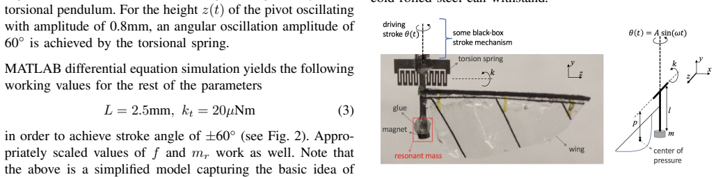
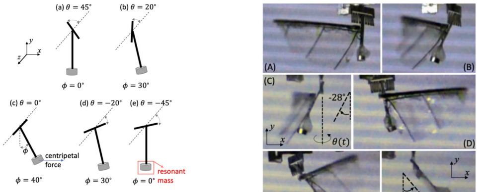
The load-bearing object is the linearly driven torsional pendulum: a lumped point mass on a torsional spring whose base is driven sinusoidally, with equation $I_x\ddot{\theta} = -k_t\theta - bL_w^2\dot{\theta} - bL_w\dot{z}\cos\theta - m_r L\cos\theta\,\ddot{z}$. At resonance this amplifies small base motion to large rotation. Physically it is realized as a planar, single-material compliant pivot—16 parallel beams laser-cut from 301 stainless steel—which rotates about one axis with low stress. The pitch mechanism uses the same torsional-spring idea but replaces the aerodynamic restoring torque with centripetal forces generated by a resonant mass (a small magnet) placed off-axis, described by equation (4). The resonance mass is the tuning knob: changing $m_r$ or the added magnet changes both stroke and pitch amplitude post-fabrication.
What would settle it
Measure the frequency response of the bare laser-cut spring on a shaker: if the resonance peak does not occur at the predicted $\omega=\sqrt{k_t/(m_r L^2)}$ (with $m_r\approx18$ mg at $L=2.5$ mm) or if the steady-state rotation amplitude falls below $60^\circ$ under the actuator's specified displacement, the lumped transmission model is falsified. Similarly, for the pitch mechanism, vary wing area or add artificial damping to a fixed wing and check whether pitch amplitude changes by more than the few degrees that would indicate sensitivity to aerodynamic loading.
Extended reading notes
Core claim
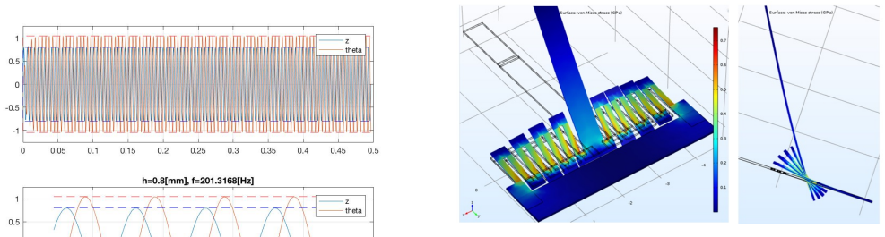
On the paper's own terms, the central discovery is that a linearly driven torsional pendulum—a point mass $m_r$ at radius $L$ on a torsional spring of stiffness $k_t$, driven by vertical motion $z(t)=z_{\max}\sin(\omega t)$—can convert small linear actuator displacements into $\pm60^\circ$ rotary wing stroke, provided the drive frequency $\omega$ matches resonance $\sqrt{k_t/I_x}$. With $z_{\max}=0.8$ mm, $m_r=2$ mg, $L=2.5$ mm, and $k_t=20\,\mu$N$\cdot$m, the simulated amplitude reaches $60^\circ$, and a laser-cut 301 stainless-steel compliant pivot with 16 parallel beams realizes the torsional spring. The same paper claims a passive pitch mechanism where the centripetal force $m l \sin(\phi)(A\omega\cos(\omega t))^2 l\cos(\phi)$ from a 4 mg magnet at distance $l=5$ mm dominates the aerodynamic torque, producing $\phi=\pm45^\circ$ pitch with little dependence on wing loading.
Load-bearing premise
The load-bearing premise is that the real laser-cut steel spring with its distributed resonant mass behaves exactly like the ideal lumped point-mass torsional pendulum of Eq. (1), so that the chosen $L=2.5$ mm and $k_t=20\,\mu$N$\cdot$m produce a $\pm60^\circ$ stroke in practice; the paper presents no modal analysis, measured stiffness, or frequency-response data to verify that this lumped idealization transfers to the fabricated device.
Editorial extensions
If this is right
- Any linear actuator that can deliver enough power can be attached directly: the transmission amplifies whatever periodic linear displacement it produces to ±60° stroke.
- Stroke and pitch mechanisms are planar and single-material, so fabrication is a single laser-cutting step with no assembly.
- Pitch amplitude can be retuned post-fabrication by adjusting the resonant mass, removing the need to redesign the flexure hinge.
- Pitch is decoupled from aerodynamic loading, so wing morphology (shape, size, weight) can be changed without iterating on hinge stiffness.
- Because inertial forces dominate over damping, the design could extend to heavier wings and non-air fluid media such as water.
Reading between the lines
- The lumped-point-mass model neglects the distributed mass of the actual steel spring; if the real mode shape differs substantially from a rigid pendulum, the resonance frequency and amplitude could shift with fabrication variance, so a modal or frequency-response measurement would be the next test.
- The same resonant-transmission idea could be adapted to other micro-scale mechanisms that need large rotations from small linear strokes, such as scanning mirrors or micro-valves, where the universal-actuator property would be attractive.
- Because the pitch mechanism relies on centripetal acceleration, it would be interesting to test whether the decoupling degrades at stroke frequencies far from resonance, where the aerodynamic term might no longer be negligible.
- A stronger experimental demonstration would measure pitch amplitude versus wing size (or versus wind speed) to quantify the claimed insensitivity.
Signed reviews
Editorial analysis
A structured set of objections, weighed in public.
Referee Report
Summary. The manuscript proposes two mechanisms for milligram-scale flapping-wing aerial devices: a planar compliant transmission that converts linear actuator motion into ±60° rotary wing stroke via a linearly driven torsional pendulum, and a passive wing-pitch mechanism driven by centripetal forces that is claimed to be largely independent of aerodynamic loading. The design is described by lumped-parameter ODEs, with parameter values selected from MATLAB simulations, and demonstrated qualitatively on a benchtop setup at 70 Hz.
Significance. If these mechanisms work as claimed, they would offer a genuinely simple, single-material, assembly-free transmission for insect-scale robots and a passive pitch mechanism that decouples wing kinematics from aerodynamic load. The conceptual move from displacement-amplification transmissions to resonant transmissions is interesting and potentially important for simplifying microfabrication. Contributions include the explicit ODE models, the design recipes for k_t and L, and proof-of-concept demonstrations. However, as presented, the quantitative claims rest on an incorrect static torque argument and on demonstrations that do not measure the claimed amplitudes, so the significance is presently prospective rather than established.
major comments (3)
- [Section II.A (Eq. (1) and static torque argument)] The static justification for the spring constant is incorrect. The base-excitation torque amplitude in Eq. (1) is mr L ω² zmax, which with the stated values (mr=2 mg, L=2.5 mm, zmax=0.8 mm, ω=2π·200 Hz) is about 6.3 µNm, not the claimed mrω²L·L ≈ 20 µNm. The centripetal force mrω²L is radial and produces no torque about the pivot, so the relation T/k_t = 1 rad does not follow. Moreover, at resonance the steady-state amplitude is governed by damping, not by the static torque-balance relation. This error undermines the numerical values in Eq. (3) and the associated claim that the transmission recipe is universally applicable.
- [Section II.B and Section III (lumped-model-to-hardware transfer)] The paper explicitly acknowledges that the real 16-beam steel spring has a distributed resonant mass, unlike the point mass mr assumed in Eq. (1), but it supplies no modal analysis, no measured torsional stiffness, and no frequency-response data for the fabricated spring. The only validation is a bench demonstration at 70 Hz with a hand-tuned mr≈18 mg, judged from photographs. This does not verify the quantitative design recipe (L=2.5 mm, k_t=20 µNm at 200 Hz with mr=2 mg), and it leaves open the possibility that the fabricated spring's first mode is not the assumed rigid-body rotation. Consequently, the central universality claim is not supported by the experimental evidence.
- [Section III (pitch mechanism validation)] The pitch mechanism is demonstrated only qualitatively: the resonant mass is 'tuned using glue and attaching smaller magnets till a decent wing pitch amplitude is observed,' and no quantitative pitch amplitude is reported. The claim that pitch motion has little dependence on aerodynamic loading is based solely on estimated torque magnitudes (2.5 µNm aerodynamic vs. 8 µNm inertial) rather than on measurements with varying wing loading. A controlled experiment that varies aerodynamic load (e.g., wing size or airspeed) and measures pitch amplitude is needed to support the decoupling claim.
minor comments (5)
- [Abstract and Introduction] The phrase 'simplest transmission mechanism ever designed' is an unverifiable superlative; please either provide a systematic comparison with existing planar compliant transmissions or soften the wording.
- [Section II.A (static torque argument)] The statement '1rad ≈ π/3 rad = 60°' is incorrect: 1 rad ≈ 57.3°, while π/3 rad ≈ 1.047 rad. Although the intended approximation may be acceptable, the displayed equality should be fixed.
- [Section II.B / Table I] The bench demonstration in Section III uses a spring with dimensions given in Table I, but the text does not state whether the tuned mr≈18 mg is added to the same spring or to a different version; please clarify the experimental configuration.
- [Section II.C (Eq. (4))] The notation 'ml sin(φ)(Aω cos(ωt))2l cos(φ)' is ambiguous; please rewrite the centripetal torque term as ml² sin φ cos φ (Aω cos ωt)² or an equivalent explicit expression.
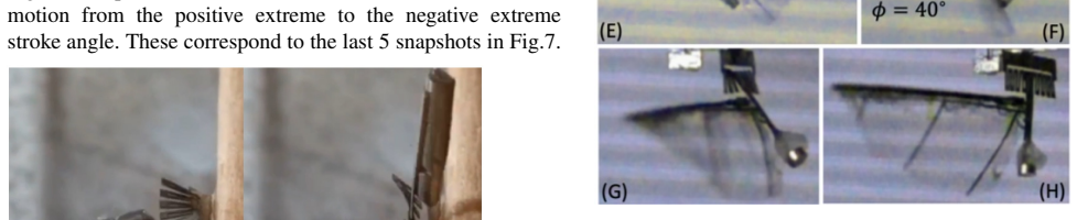
- [Section III (Fig. 6)] Please add a scale bar or known reference dimension to Fig. 6 so that the claimed 'amplitudes exceeding ±60°' can be independently assessed from the photograph rather than taken on faith.
Circularity Check
No significant circularity: design parameters are synthesis choices, and the bench demonstrations are qualitative rather than quantitative predictions.
full rationale
The paper's derivation chain is self-contained: Section II.A sets up a driven torsional-pendulum ODE (Eq. 1), chooses representative actuator inputs (zmax=0.8 mm, f≈200 Hz, mr=2 mg) and an estimated damping law (Eq. 2), then solves the ODE to obtain L=2.5 mm and kt=20 µNm for a ±60° stroke. This is inverse design: parameters are selected to meet a target, not fitted to data and then relabeled as predictions. The Section III experiment is explicitly a demonstration at 70 Hz with mr tuned to ≈18 mg 'to observe resonance', and the result is reported qualitatively as amplitudes 'exceeding ±60°'; no measured quantity is compared to a quantitative model prediction, so there is no fitted-input-called-prediction step. The pitch mechanism likewise uses Eq. (4) to select l=5 mm and k=20 µNm 'in order to achieve φ=±45°'—again design synthesis, not prediction. The claim of weak dependence on aerodynamic loading is supported by independent order-of-magnitude estimates of the inertial term (8 µNm) versus the aerodynamic term (2.5 µNm); these estimates rely on model parameters but are not equivalent to the conclusion by construction. The fabrication method is cited to the authors' prior work [6], [9], but the load-bearing physics (Eqs. 1 and 4) is stated and analyzed in the present paper, and no uniqueness theorem or external authority is invoked to force a choice. The static-torque sentence in Section II.A ('20 µNm acting on a kt=20 µNm spring will cause an angular displacement of 1rad ≈ π/3 rad') is numerically imprecise and ignores resonance, but it is an informal consistency check rather than the derivation, which is the ODE simulation. The absence of measured stiffness or frequency-response data is a validation and correctness concern, not a circularity, because the paper does not claim to have quantitatively predicted the experimental amplitudes. Accordingly, no circular step can be exhibited from the text, and the score is 0.
Assumptions & free parameters
free parameters (5)
- mr (transmission resonant mass) =
2 mg (simulation), ~18 mg (experiment)
- kt (torsional spring constant) =
20 µNm
- L (resonant mass radius) =
2.5 mm
- l (pitch magnet offset) =
5 mm
- b (aerodynamic damping coefficient) =
Computed via Eq. (2), approximately 1.5e-3 / (Lw ω π/3 + zmax ω)
assumptions (5)
- standard math A harmonically driven torsional pendulum (Eq. 1) adequately models the wing stroke transmission.
- domain assumption Aerodynamic forces on the wing can be represented by a linear damping coefficient b, and inertial/elastic forces dominate.
- domain assumption The fabricated distributed resonant mass and compliant spring behave like the idealized point-mass pendulum.
- domain assumption In the pitch mechanism, centripetal forces on the magnet drive wing pitch, and aerodynamic torque can be neglected.
- ad hoc to paper Any linear actuator with 'sufficient power' can drive the transmission universally.
Cite this review
Pith. "Pith review of New Wing Stroke and Wing Pitch Approaches for Milligram-scale Aerial Devices." pith.science (2026). https://pith.science/paper/VPUYKWGH
@misc{pith2026190803422,
  author       = {Pith},
  title        = {Pith review of: New Wing Stroke and Wing Pitch Approaches for Milligram-scale Aerial Devices},
  year         = {2026},
  howpublished = {\url{https://pith.science/paper/VPUYKWGH}},
  note         = {Machine review of arXiv:1908.03422}
}
abstract
Here we report the construction of the simplest transmission mechanism ever designed capable of converting linear motions of any actuator to $\pm$60$^\circ$ rotary wing stroke motion. It is planar, compliant, can be fabricated in a single step and requires no assembly. Further, its design is universal in nature, that is, it can be used with any linear actuator capable of delivering sufficient power, irrespective of the magnitude of actuator displacements. We also report a novel passive wing pitch mechanism whose motion has little dependence on the aerodynamic loading on the wing. This exponentially simplifies the job of the designer by decoupling the as of yet highly coupled wing morphology, wing kinematics and flexure stiffness parameters. Like the contemporary flexure-based methods it is an add-on to a given wing stroke mechanism. Moreover, the intended wing pitch amplitude could easily be changed post-fabrication by tuning the resonance mass in the mechanism.
Figures

Figures from the paper (2 more)
Reference graph
Works this paper leans on
-
[1]
K. Ma, P. Chirarattanon, S. Fuller, and R.J. Wood, ``Controlled Flight of a Biologically Inspired, Insect-Scale Robot,'' Science , vol. 340, pp. 603-607, 2013
work page 2013
-
[2]
X. Yan, Z. Liu, M. Qi, L. Lin, ``Low Voltage Electromagnetically Driven Artificial Flapping Wings,'', MEMS , pp 1149-1152, Jan. 2016
work page 2016
-
[3]
Z. Liu, X. Yan, M. Qi, Y. Yang, X. Zhang, L. Lin, ``Lateral Moving of an Artificial Flapping-Wing Insect Driven by Low Voltage Electromagnetic Actuator,'', MEMS , pp 777-780, Jan. 2016
work page 2016
-
[4]
X. Yan, M. Qi, and L. Lin, ``Self-Lifting Artificial Insect Wings via Electrostatic Flapping Actuators,'' Proceedings of 28th IEEE Micro Electro Mechanical Systems Conference , pp. 22-25, Portugal, Jan. 2015
work page 2015
-
[5]
Y. Zou, W. Zhang, and Z. Zhang, ``Liftoff of an Electromagnetically Driven Insect-Inspired Flapping-Wing Robot,'' IEEE Transactions on Robotics , vol. 32, no. 5, October 2016
work page 2016
-
[6]
P. Bhushan and C.J. Tomlin, ``Milligram-scale Micro Aerial Vehicle Design for Low-voltage Operation,'' IROS , Madrid, Spain, Oct. 2018
work page 2018
-
[7]
J. P. Whitney and R. J. Wood, ``Aeromechanics of passive rotation in flapping flight,'' J. Fluid Mech. , vol. 660, pp. 197-220, 2010
work page 2010
-
[8]
M. Karpelson, G-Y. Wei, and R.J. Wood, ``A Review of Actuation and Power Electronics Options for Flapping-Wing Robotic Insects,'' IEEE Int. Conf. on Robotics and Automation , Pasadena, CA, May, 2008
work page 2008
Show all 12 references
-
[9]
Bhushan and C.J
P. Bhushan and C.J. Tomlin, ``Design of the first sub-milligram flapping wing aerial vehicle,'' MEMS , Seoul, South Korea, Jan. 2019
2019
-
[10]
Malka, A.L
R. Malka, A.L. Desbiens, Y. Chen, and R. J. Wood, ``Principles of Microscale Flexure Hinge Design for Enhanced Endurance,'' IROS , Chicago, IL, Sept. 2014
2014
-
[11]
R. J. Wood, ``Liftoff of a 60mg flapping-wing MAV,'' IROS , San Diego, CA, Oct. 2007
2007
-
[12]
q 2 #B R 3br w !1 AQ aq
11em plus .33em minus .07em 4000 4000 100 4000 4000 500 `\.=1000 = #1 \@IEEEnotcompsoconly \@IEEEcompsoconly #1 * [1] 0pt [0pt][0pt] #1 * [1] 0pt [0pt][0pt] #1 * \| ** #1 \@IEEEauthorblockNstyle \@IEEEcompsocnotconfonly \@IEEEauthorblockAstyle \@IEEEcompsocnotconfonly \@IEEEco...
1999
Reviewed August 14, 2026 · model on record in the stance chip above.
Discussion (0). Continue with ORCID to comment.