REVIEW 2 major objections 5 minor 23 references
Ultrafast Laser Inscription of High Performance Mid-Infrared Waveguides in Chalcogenide Glass
T0 review · 2 major / 5 minor · reviewed 2026-08-14 · deepseek-v4-flash
Pith's one-line read Multicore waveguides written by ultrafast laser inscription in chalcogenide glass guide 4.5 µm light with 0.20 ± 0.05 dB/cm loss and over 60% coupling efficiency.
desk verdict The 0.20 dB/cm mid-IR loss claim is a plausible record, but it rests on one back-reflection measurement with no cutback check; worth reviewing, needs experimental corroboration. read the letter →
The pith
A machine-rendered reading of the paper's core claim, the machinery that carries it, and where it could break.
The reading
What carries the argument
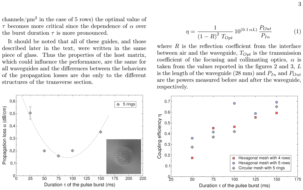
The central object is the multicore waveguide: an array of parallel positive-refractive-index channels, each produced by a femtosecond-laser filament whose diameter is fixed by the glass, with the channels arranged on a hexagonal or concentric-ring mesh. The index contrast $\Delta n$ of each channel is controlled by the burst duration $\tau$ of the pulse train, which sets the compromise between poor confinement (small $\tau$) and field localization inside single channels (large $\tau$); the optimal $\tau$ minimizes propagation loss. The overall transverse size is set separately by the number and spacing of channels, giving independent control of $\Delta n$ and guide diameter. Losses are obtained with the back-reflection method; coupling efficiency is derived from Eq. (1), which corrects the power ratio for Fresnel reflection, optics transmission, and propagation loss.
What would settle it
A cutback test with identical guides of several lengths (for example 10, 20, and 40 mm) would settle the loss claim: the slope of measured insertion loss versus length must equal $0.20$ dB/cm and the intercept must match an independently calibrated coupling loss. Separately calibrating $T_{\mathrm{Opt}}$ with a reference optic of known transmission would check the reported coupling efficiencies above 60%.
Extended reading notes
Core claim
On its own terms, the paper's discovery is that a multicore geometry—parallel positive-index channels written on a hexagonal or concentric-ring mesh—lets ultrafast laser inscription produce a single-mode mid-infrared waveguide in an arsenic-free chalcogenide glass with propagation loss $0.20 \pm 0.05$ dB/cm at 4.5 µm and coupling efficiency higher than 60%. The authors find the minimal loss is identical for 4-row and 5-row hexagonal meshes and for a 5-ring circular mesh, and take this as evidence that the index-contrast channels are homogeneous and that stitching successive transverse slices introduces no extra scattering. They further show the index contrast $\Delta n$ can be tuned through the burst duration $\tau$ while the overall guide diameter is set independently by the channel spacing and count, so mode size and confinement can be engineered for efficient light collection. Combining these results with the earlier $0.11 \pm 0.03$ dB/cm at 1.55 µm, the authors conclude the method can cover the 1.5–4.5 µm range in one glass platform.
Load-bearing premise
The load-bearing premise is that the back-reflection measurement on a single 28 mm guide, whose total loss is only about 0.56 dB, gives the true propagation loss without an independent cutback check, and that the optics transmission $T_{\mathrm{Opt}}$ in Eq. (1) is correctly calibrated.
Editorial extensions
If this is right
- A laser-written chalcogenide waveguide can carry 4.5 µm light at propagation loss below 0.2 dB/cm, a level the paper argues is better than current photowritten and silicon-based mid-IR waveguides.
- The same inscription procedure yields low loss at 1.55 µm and at 4.5 µm, so one material and one writing method can serve devices across the 1.5–4.5 µm band.
- Because the guide diameter and index contrast are independently adjustable, the transverse mode can be matched to fibers or free-space beams, reducing coupling losses in practical systems.
- The burst duration can be chosen according to device length: short devices should prefer higher $\tau$ to maximize coupled power, while long devices should prefer the $\tau$ that minimizes loss.
- The loss minimum being independent of channel density suggests the writing method is stable across mesh designs, which supports extension to curved guides and more complex circuits.
Reading between the lines
- If an independent cutback measurement on several guide lengths confirms the 0.20 dB/cm figure, femtosecond-laser-written chalcogenide waveguides would move into the loss class needed for practical mid-IR evanescent-wave gas sensors, not just laboratory demonstrations.
- The equality of the loss minimum across different meshes suggests the residual loss is set by the glass matrix or the channel material rather than by mesh geometry; writing the same multicore structure in glasses with different germanium/gallium ratios would test this.
- Eq. (1) implies a design rule the paper states only qualitatively: for a fixed input power, the best $\tau$ maximizes transmitted power, which for a given device length is a trade-off between $\alpha$ and $\eta$ that could be plotted explicitly.
- The paper projects but does not demonstrate operation beyond 4.5 µm; measuring the same guides at 7–10 µm would check whether the method's advantage persists up to the glass's transmission edge.
Signed reviews
Editorial analysis
A structured set of objections, weighed in public.
Referee Report
Summary. The manuscript reports ultrafast laser inscription of multicore waveguides in 72GeS2-18Ga2S3-10CsCl chalcogenide glass and characterizes them at 4.5 µm. Two hexagonal-mesh configurations and one circular-mesh configuration are written with varying burst duration τ. The authors report a minimum propagation loss of 0.20 ± 0.05 dB/cm, coupling efficiencies above 60%, and Gaussian-like near-field mode profiles, and they interpret the results as evidence of homogeneous refractive-index channels with no additional scattering from slice concatenation. They also discuss the trade-off between coupling efficiency and propagation loss as τ varies.
Significance. The reported value of 0.20 ± 0.05 dB/cm at 4.5 µm would be a substantial improvement over previously published photowritten chalcogenide and silicon-based mid-IR waveguides, and the ability to independently control Δn and structure diameter is useful for practical coupling. Strengths of the paper include the direct, non-circular measurement procedure: all quantities are measured externally, the Fresnel correction uses an independently known refractive index [23], and the back-reflection method has been established for waveguide loss measurement [22]. If the loss value is confirmed by an independent method, the result would be of clear interest to the mid-IR photonics community.
major comments (2)
- [Section III, Fig. 2] The central claim of 0.20 ± 0.05 dB/cm rests on a single back-reflection measurement on a 28 mm waveguide. The one-way loss over this length is only about 0.56 dB, and the stated uncertainty corresponds to ±0.14 dB over the same length; systematic errors in the back-reflection method (spatial separation of input and output reflections, back-coupling at the exit facet, mode conversion in the multicore structure, and Fresnel-coefficient calibration) can easily be of this magnitude. No cutback, length-dependent, or independently repeated measurement is reported, so the accuracy of the headline loss value is not externally established. I ask the authors to add a cutback or two-length verification, or at minimum to report the repeatability and the dominant systematic-error budget.
- [Eq. (1), Fig. 4] The coupling-efficiency values rely on the optics transmission TOpt, but the manuscript does not state how TOpt was calibrated or measured, nor are uncertainties in η, R, or the power measurements given. Although the propagation-loss correction 10^(0.1αL) is only about 1.14 for α = 0.2 dB/cm and L = 28 mm, an uncalibrated system-level factor in TOpt could shift η by a larger, unknown amount. Please report the TOpt calibration procedure and propagate uncertainties into η, including error bars in Fig. 4; without this information, the 'higher than 60%' coupling claim is not quantitatively supported.
minor comments (5)
- [Section IV] The first sentence of the conclusions states 'propagation loss below 0.2 dB/cm,' which is not consistent with the abstract's measured value of 0.20 ± 0.05 dB/cm; use the same number with its uncertainty throughout.
- [Section III and Section IV] The final sentence of the conclusions says that the authors 'do not take into account Fresnel loss' after reporting efficiencies obtained with Eq. (1), which includes the (1 − R)^2 factor; clarify whether η is Fresnel-corrected and whether the 'carried power' statement refers to η or to a different quantity.
- [Section II] The text contains 'channelx' and 'channely' that should read 'channel x' and 'channel y', and 'in the plan of the transverse section' should be 'in the plane of the transverse section'.
- [Fig. 4] The coupling efficiencies are presented as point measurements without error bars, so it is unclear whether the ranking of the three structures at a given τ is significant; add repeat-measurement statistics.
- [Section III, Fig. 5] The single-mode claim is based solely on a near-Gaussian near-field image; a mode-cutoff study or an M² measurement would make this claim more robust.
Circularity Check
No significant circularity; all reported values are direct measurements using standard external methods.
full rationale
The paper's central claims—propagation loss of 0.20 ± 0.05 dB/cm and coupling efficiencies above 60%—are presented as direct measurements, not as predictions derived from a model. The propagation loss is obtained via the back-reflection method with the method cited to an external reference [22], and the Fresnel reflection correction uses an independently published refractive index [23]. Equation (1) uses the measured α to de-embed coupling efficiency from power measurements; this is a standard correction, not a fitted input renamed as a prediction. The authors' self-citations [18,20,21,23] provide prior context and material characterization, but the load-bearing loss and efficiency values do not reduce to those citations. The absence of a cutback verification and the unspecified calibration of T_opt are legitimate experimental-support concerns, but they are not circularity. The derivation chain, such as it is, is self-contained in the sense that the reported quantities are measured rather than defined into existence.
Assumptions & free parameters
assumptions (4)
- domain assumption The back-reflection loss measurement [22] accurately yields propagation loss without cutback verification.
- domain assumption Quantitative phase microscopy with Abel inversion gives correct refractive index contrast Δn values for the written channels.
- domain assumption The concatenation of transverse slices along the writing direction does not add significant irregularity or scattering.
- domain assumption A Gaussian-like near-field profile implies single-mode behavior.
Cite this review
Pith. "Pith review of Ultrafast Laser Inscription of High Performance Mid-Infrared Waveguides in Chalcogenide Glass." pith.science (2026). https://pith.science/paper/O6NL3SZJ
@misc{pith2026190803452,
  author       = {Pith},
  title        = {Pith review of: Ultrafast Laser Inscription of High Performance Mid-Infrared Waveguides in Chalcogenide Glass},
  year         = {2026},
  howpublished = {\url{https://pith.science/paper/O6NL3SZJ}},
  note         = {Machine review of arXiv:1908.03452}
}
abstract
We present the realization of mid-infrared waveguide by ultrafast laser inscription technique in a chalcogenide glass. Our approach is based on multicore waveguide that consists in an alignment on a mesh of positive refractive index channels placed parallel to each other. Two different meshes are investigated with different refractive index contrasts between the channel and the glass matrix. A detailed analysis of the performances at a wavelength of 4.5 $\mu$m shows propagation losses of 0.20 $\pm$ 0.05 dB/cm and coupling efficiencies higher than 60 %.
Figures


Figures from the paper (1 more)

Reference graph
Works this paper leans on
-
[23]
P. Masselin, D. Le Coq, L. Calvez, E. Petracovschi, E. Lépine, E. Bychkov, and X. Zhang, Applied Physics A: Materials Science & Processing106, 697 (2012)
work page 2012
-
[22]
R. Ramponi, R. Osellame, and M. Marangoni, Review of Scientific Instruments73, 1117 (2002)
work page 2002
-
[1]
Mid-Infrared Technologies for Health and the Environment,
Project MIRTHE, “Mid-Infrared Technologies for Health and the Environment,” http://www.mirthe-erc.org/ mirthecenter
-
[2]
Mid to NEaR infrared spec- troscopy for improVed medical diAgnostic,
Project FP7 MINERVA, “Mid to NEaR infrared spec- troscopy for improVed medical diAgnostic,”http://www. minerva-project.eu
-
[3]
Flying ultrA-broadband single-shot Infra-Red sensor,
Project FLAIR, “Flying ultrA-broadband single-shot Infra-Red sensor,”https://www.h2020flair.eu/
-
[4]
Mid InfraRed Innovative lasers For Improved SENSor of hazardeous substances,
Project FP7 MIRIFISENS, “Mid InfraRed Innovative lasers For Improved SENSor of hazardeous substances,” http://www.mirifisens-project.eu
- [5]
-
[6]
J. Soler Penades, A. Ortega-Moñux, M. Nedeljkovic, J. G. Wangüemert-Pérez, R. Halir, A. Z. Khokhar, C. Alonso-Ramos, Z. Qu, I. Molina-Fernández, P. Cheben, and G. Z. Mashanovich, Opt. Express 24, 22908 (2016)
work page 2016
Show all 23 references
-
[7]
P. T. Lin, V. Singh, Y. Cai, L. C. Kimerling, and A. Agarwal, Opt. Lett.38, 1031 (2013)
2013
-
[8]
F. Li, S. D. Jackson, C. Grillet, E. Magi, D. Hudson, S. J. Madden, Y. Moghe, C. O’Brien, A. Read, S. G. Duvall, P. Atanackovic, B. J. Eggleton, and D. J. Moss, Opt. Express 19, 15212 (2011)
2011
-
[9]
Singh, D
N. Singh, D. D. Hudson, Y. Yu, C. Grillet, S. D. Jackson, A. Casas-Bedoya, A. Read, P. Atanackovic, S. G. Duvall, S. Palomba, B. Luther-Davies, S. Madden, D. J. Moss, and B. J. Eggleton, Optica2, 797 (2015)
2015
-
[10]
Chang, V
Y.-C. Chang, V. Paeder, L. Hvozdara, J.-M. Hartmann, and H. P. Herzig, Opt. Lett.37, 2883 (2012)
2012
-
[11]
M. Brun, P. Labeye, G. Grand, J.-M. Hartmann, F. Boulila, M. Carras, and S. Nicoletti, Opt. Express 22, 508 (2014)
2014
-
[12]
J. M. Ramirez, V. Vakarin, C. Gilles, J. Frigerio, A. Bal- labio, P. Chaisakul, X. L. Roux, C. Alonso-Ramos, G. Maisons, L. Vivien, M. Carras, G. Isella, and D. Marris-Morini, Opt. Lett.42, 105 (2017)
2017
-
[13]
J. M. Ramirez, Q. Liu, V. Vakarin, J. Frigerio, A. Bal- labio, X. L. Roux, D. Bouville, L. Vivien, G. Isella, and D. Marris-Morini, Opt. Express26, 870 (2018)
2018
-
[14]
Osellame, G
R. Osellame, G. Cerullo, and R. Ramponi,Femtosecond Laser Micromachining: Photonic and Microfluidic De- vices in Transparent Materials, Topics in Applied Physics (Springer, 2012)
2012
-
[15]
Ródenas, G
A. Ródenas, G. Martin, B. Arezki, N. Psaila, G. Jose, A. Jha, L. Labadie, P. Kern, A. Kar, and R. Thomson, Opt. Lett. 37, 392 (2012)
2012
-
[16]
D’Amico, G
C. D’Amico, G. Cheng, C. Mauclair, J. Troles, L. Calvez, V. Nazabal, C. Caillaud, G. Martin, B. Arezki, E. LeCoarer, P. Kern, and R. Stoian, Opt. Express22, 13091 (2014). 5
2014
-
[17]
H. L. Butcher, D. G. MacLachlan, D. Lee, R. R. Thom- son, and D. Weidmann, Opt. Express26, 10930 (2018)
2018
-
[18]
Masselin, E
P. Masselin, E. Bychkov, and D. Le Coq, Opt. Lett.41, 3507 (2016)
2016
-
[19]
Ampem-Lassen, S
E. Ampem-Lassen, S. T. Huntington, N. M. Dragomir, K. A. Nugent, and A. Roberts, Opt. Express13, 3277 (2005)
2005
-
[20]
Caulier, D
O. Caulier, D. Le Coq, L. Calvez, E. Bychkov, and P. Masselin, Opt. Express19, 20088 (2011)
2011
-
[21]
Caulier, D
O. Caulier, D. Le Coq, E. Bychkov, and P. Masselin, Opt. Lett. 38, 4212 (2013)
2013
Reviewed August 14, 2026 · model on record in the stance chip above.
Discussion (0). Continue with ORCID to comment.