REVIEW 3 major objections 4 minor 21 references
Optimization-based Settingless Algorithm Combining Protection and Fault Identification
T0 review · 3 major / 4 minor · reviewed 2026-08-14 · deepseek-v4-flash
Pith's one-line read A settingless protection algorithm decides whether a power line is healthy or faulted by solving convex optimization problems that fit measured waveforms to both line models, and it locates and classifies the fault in the same step.
desk verdict A genuinely new convex model-selection approach to settingless line protection with strong simulation work, but the fault-identifiability claim is undercut by a real linear-algebra gap and the model-selection rule lacks a complexity penalty. read the letter →
The pith
A machine-rendered reading of the paper's core claim, the machinery that carries it, and where it could break.
The reading
What carries the argument
The load-bearing object is the pair of line models in equations (1)-(4): a healthy lumped-parameter R-L line and the same line with a shunt fault represented by a $3\times 3$ fault-resistance matrix $Z_F$ parameterized by $R_a,R_b,R_c,R_g$ and location $\alpha$. Around these models the paper builds a model-selection procedure: for each hypothesis about the observation window it minimizes the mean squared mismatch of the model equations, which for fixed measurement matrices becomes a convex quadratic program $x^T H x + F^T x + d$ with bound constraints that can be solved to global optimality. This convexity is what lets one calculation both make the trip decision and estimate fault characteristics quickly enough for protection.
What would settle it
Run the algorithm on a large set of fault-free windows generated by the same grid model with Gaussian measurement noise near a 60 dB signal-to-noise ratio and count how often it declares an internal fault; because the faulted model has five free parameters, a nonzero false-trip rate would show that the raw error comparison needs a model-complexity penalty. A sharper test is to take a healthy-line window, deliberately mis-synchronize a few samples at one end, and check whether the faulted model absorbs the glitch and trips.
Extended reading notes
Core claim
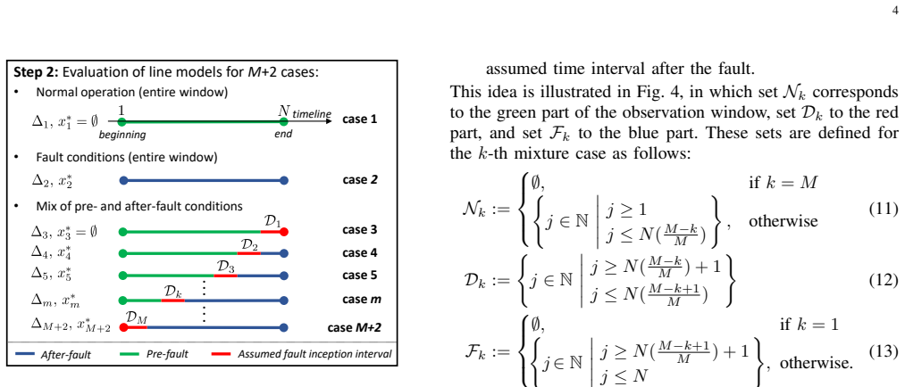
The central claim is that a settingless time-domain unit protection algorithm can decide whether a medium-voltage line is healthy or internally faulted purely by comparing how well two physics-based models explain one window of synchronized measurements. The healthy model is the differential equation of a lumped R-L line; the faulted model is the same line with a fault at relative distance $\alpha$ and resistance parameters $R_a$, $R_b$, $R_c$, $R_g$. The algorithm enumerates $M+2$ hypotheses: normal operation over the whole window, faulted operation over the whole window, and $M$ mixtures in which a suspected fault-inception interval slides across the window. For each hypothesis it computes the smallest mean squared residual of the model equations by solving a convex quadratic program in the fault parameters, then selects the hypothesis with the smallest error as the true state, using a ratio-based tie-break when the healthy case and the first mixture case are numerically close. The paper reports 100% detection of all simulated internal faults, no false trips for normal operation or external faults, accurate fault-location and resistance estimates, correct inception-interval identification, and stable performance with converter-based generation for signal-to-noise ratios down to roughly 60 dB and line-parameter errors up to about 10%.
Load-bearing premise
The algorithm assumes that the model with the smaller average squared fitting error is the true state of the line, even though the faulted model has five extra adjustable parameters and can therefore fit noise and measurement glitches more easily.
Editorial extensions
If this is right
- Because the same optimization problems yield both the trip decision and the fault parameters, a relay using the algorithm can send a trip signal and a fault report (location, type, resistances, inception interval) to operators at the same time.
- Removing threshold set-points means the algorithm does not need to be re-tuned when grid conditions or fault characteristics change, which the paper shows by testing across different source types, noise levels, and line-parameter errors.
- The algorithm's security against external faults and normal operation was maintained in all reported scenarios, so it can replace phasor-based relays that may be unreliable with converter-based distributed generation.
- Within a 2 ms observation window and with communication-plus-propagation delays below 1 ms, the remaining computation budget of under 1 ms is achievable with dedicated hardware, so the approach is compatible with sub-cycle protection speeds.
Reading between the lines
- An immediate testable extension would be to add a model-complexity penalty (e.g., an information criterion) to the mean squared error comparison; the paper's Section III-D heuristic $a_1$ vs $a_2$ suggests the authors already saw the need to break ties at low error levels, and a principled penalty could remove the heuristic altogether.
- The same model-selection machinery could be applied to transmission lines, but only if the lumped R-L model is replaced by a distributed-parameter model, which would make the optimization non-convex; the paper marks this as future work.
- The sliding inception-interval design implies a natural refinement: once a faulted window is found, run the mixture cases again with a finer grid over the selected interval only, which should improve inception-time estimates without increasing the original computational budget.
- A practical deployment constraint not explored in the paper is sensitivity to synchronization errors between the two line ends; because equations (1)-(4) assume time-aligned samples, the 100 kHz sampling and optical-transformer requirements could be paired with a synchronization-error test to see how much misalignment the convex fit tolerates.
Signed reviews
Editorial analysis
A structured set of objections, weighed in public.
Referee Report
Summary. The manuscript proposes a settingless time-domain unit protection algorithm for medium-voltage lines. The algorithm evaluates M+2 hypotheses for each observation window: a healthy line over the full window, a faulty line over the full window, and M mixed pre-/post-fault windows. Each faulty hypothesis is formulated as a small convex quadratic program in the fault resistances Ra, Rb, Rc, Rg and the fault location α, and the hypothesis with the smallest mean-squared error is selected. The optimized resistances and α are then used for fault type identification and fault location. The authors evaluate the algorithm on a Simulink implementation of a lumped R-L line model under normal operation, external faults, internal faults, converter-based generation, measurement noise, and line-parameter uncertainty, reporting 100% dependability and security over the tested scenarios and accurate fault-parameter estimates for SNR ≥ 60 dB and ±10% line-parameter errors.
Significance. The central idea—recasting protection as a model-selection problem solved by small convex programs with no empirical thresholds—is novel and potentially useful for MV time-domain protection. The authors also provide extensive simulation coverage of generation types and operating conditions, and the computational footprint appears compatible with relay time budgets. However, the paper's as-stated claim that the algorithm merges protection, fault location, and fault type identification is stronger than what the presented evidence supports: the fault-resistance identification problem is rank-deficient for common fault types, the model-selection rule has no complexity penalty, and the validation uses the same lumped R-L model that the algorithm assumes. These issues are load-bearing for the merged-functionality claim and need to be addressed in revision.
major comments (3)
- [Section III-C, Eq. (10)] The claim that H is positive definite is not correct for typical fault types. For a single-line-to-ground fault, KCL at the fault node gives I1p+I2p ≈ 0 for the two unfaulted phases, so in the regression matrix implied by W(RF, α) in Eq. (7) the columns corresponding to Rb and Rc are near zero; for phase-to-phase faults the column for the unfaulted phase vanishes. Consequently H is only positive semidefinite, the optimal Rb/Rc are non-unique, and a QP solver will return arbitrary values for those components. This undermines the claimed fault-type identification from RF and makes the resistance-error averages in Tables III and V uninterpretable for components whose true value is infinite or unidentifiable. The protection decision may still be reliable, but the fault-identification function needs to be reformulated, for example by solving separate structured models for each fault type or by reporting only identifiable parameters.
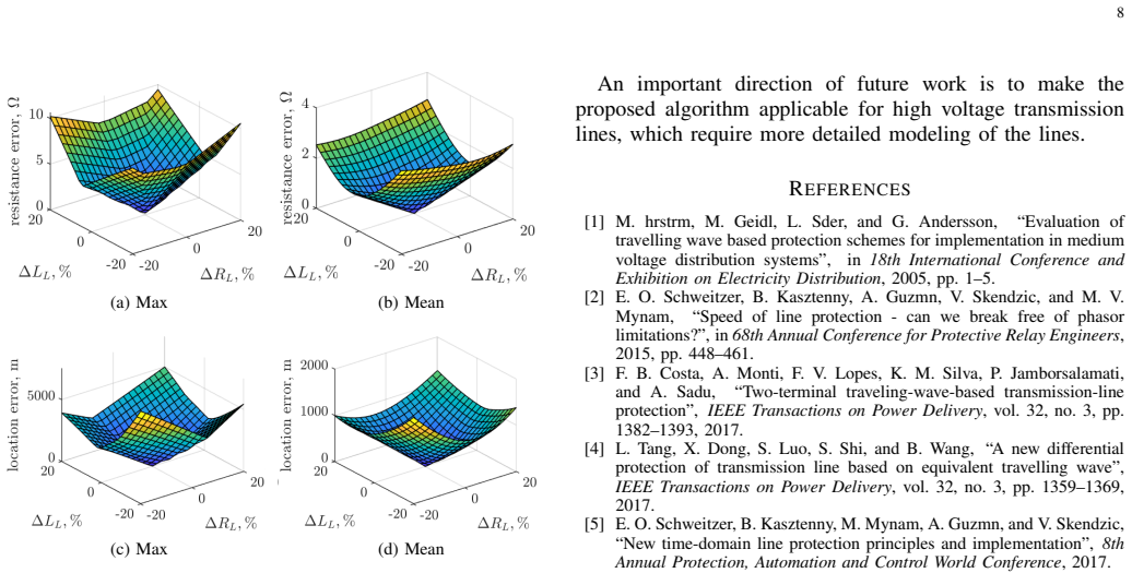
- [Section III-D] The case-selection rule compares raw mean-squared errors without penalizing the larger number of adjustable parameters of the faulty model. The healthy model has no fault parameters, whereas each faulty/mixed case has five free parameters (Ra, Rb, Rc, Rg, α); under noise the more flexible faulty model can fit the data spuriously. The heuristic a1 := ∆1/∆3 and a2 := ∆4/∆1 introduced in Section III-D is not justified by any statistical model-complexity criterion. This is the most likely reason that the security results in Section IV-F, Figure 6, degrade sharply below SNR = 60 dB. The authors should introduce a principled penalty (e.g., AIC/BIC or a chi-square test with proper degrees of freedom) or otherwise justify the model comparison; otherwise the 'settingless' claim that no thresholds are needed is not supported.
- [Section IV, simulation setup] The validation is circular in an important respect: the protected line in the Simulink model is represented with the same lumped series R-L equations, Eqs. (1)–(4), that the algorithm itself uses, with no shunt capacitance or distributed-parameter effects. The tests therefore demonstrate internal consistency between the algorithm and its own assumed model, not robustness to the dominant modeling errors of real MV lines. Since the final paragraph of the paper already notes that HV lines require more detailed modeling, the claims should be correspondingly limited for MV applications, or the algorithm should be tested on a higher-fidelity EMTP-type line model (e.g., frequency-dependent distributed-parameter) to establish that the model mismatch does not cause misoperation.
minor comments (4)
- [Section IV-A] The text states that xmax provides an upper bound on RF, but the simulation setup sets xmax := [∞, ∞, ∞, ∞, 1]^T. Please clarify whether a finite bound is actually used in the reported tests; with truly infinite bounds and rank-deficient H, the QP can have unbounded or arbitrary solutions.
- [Section IV-D, Table III] For K1 faults, Table II sets Rb = Rc = ∞, so the reported small mean resistance errors cannot be reproduced without stating how errors are computed for components whose true value is infinite; please specify whether the average is taken only over finite fault resistances.
- [Equations (3) and (4)] The current reference directions are not fully specified; in particular, the appearance of (I1+I2) in Eq. (7) presumes a particular sign convention at the fault node. Please state the directions explicitly so that the identifiability discussion is unambiguous.
- [References] Reference [1] contains garbled author names ('M. hrstrm', 'L. Sder', 'G. Andersson') and [15] says '72rd' instead of '72nd'; a careful copyedit of the reference list is needed.
Circularity Check
No circularity: the fault-characteristic outputs are the optimized fit variables of an inverse problem, and no load-bearing self-citation was found.
full rationale
The paper's derivation chain is an inverse-problem formulation rather than a prediction derived from assumptions that already contain the result. The healthy and faulted model mismatch matrices S and W are constructed directly from the line differential equations (1)-(4), and the optimization problems (9) and (14) minimize the mismatch between these model equations and the measured voltage and current samples. The outputs (R_F, alpha) are by definition the best-fit fault parameters, so reporting them as the estimated fault characteristics is the intended estimation task, not a prediction that was presupposed. The comparison of the mean squared errors Delta_m across the M+2 cases is a model-selection heuristic; it may be statistically under-penalized because the faulted model has extra adjustable parameters, and the assertion that H in (10) is positive definite is questionable for fault types where some unfaulted-phase columns vanish. However, these are correctness and robustness concerns, not circularity. The simulation validation generates data with the same lumped R-L model used by the algorithm, so it does not independently validate the model form, but this is a standard in-model-class test rather than a circular derivation. There are no load-bearing self-citations: references [11] and [12] are prior external work on setting-less protection, not the authors' own, and no uniqueness theorem or ansatz is imported from the authors' previous papers. Accordingly, no circular step can be exhibited, and the appropriate circularity score is 0.
Assumptions & free parameters
free parameters (5)
- N (observation window length) =
200 samples at 100 kHz (2 ms)
- M (number of mixture cases) =
10
- l (samples for derivative estimation) =
5
- Sampling rate =
100 kHz
- Rmax_F (upper bound on fault resistances) =
infinity (unbounded in simulation)
assumptions (4)
- domain assumption The protected line is accurately represented by a lumped R-L circuit without shunt capacitance or frequency-dependent parameters (equations 1-4).
- domain assumption Measurements from both line ends are synchronized, unbiased, and have low noise, and current derivatives can be reliably estimated from sampled data.
- ad hoc to paper The residual comparison across models with different numbers of parameters is a valid model-selection criterion without a complexity penalty.
- domain assumption The fault model of equations (3)-(4) with resistance matrix (5) covers all internal faults of interest, including high-impedance faults.
Cite this review
Pith. "Pith review of Optimization-based Settingless Algorithm Combining Protection and Fault Identification." pith.science (2026). https://pith.science/paper/A3MSYNUD
@misc{pith2026190803753,
  author       = {Pith},
  title        = {Pith review of: Optimization-based Settingless Algorithm Combining Protection and Fault Identification},
  year         = {2026},
  howpublished = {\url{https://pith.science/paper/A3MSYNUD}},
  note         = {Machine review of arXiv:1908.03753}
}
read the original abstract
The demand for faster protection algorithms is growing due to the increasingly faster dynamics in the system. The majority of existing algorithms require empirically selected set-points, which may reduce sensitivity to internal faults and cause security problems. This paper addresses these challenges by proposing a settingless time-domain unit protection algorithm for medium-voltage lines. The main idea of the algorithm is to identify which model of a protected line, i.e. healthy or with an internal fault, is more consistent with the input measurements. This is done by solving a number of small-scale convex optimization problems, which at the same time determine the characteristics of an internal fault that best fit the measurements. Thus, the proposed algorithm merges protection, fault location and fault type identification functionalities. The algorithm's performance is extensively tested on a grid model in MATLAB Simulink for different types of generation and grid operating conditions. The results demonstrate that the algorithm can operate quickly and reliably, and accurately estimate fault characteristics even in the presence of noisy measurements and uncertain line parameters.
Figures


Figures from the paper (3 more)


Reference graph
Works this paper leans on
-
[1]
M. hrstrm, M. Geidl, L. Sder, and G. Andersson, “Evaluation of travelling wave based protection schemes for implementation in medium voltage distribution systems”, in 18th International Conference and Exhibition on Electricity Distribution , 2005, pp. 1–5
work page 2005
-
[2]
Speed of line protection - can we break free of phasor limitations?
E. O. Schweitzer, B. Kasztenny, A. Guzmn, V . Skendzic, and M. V . Mynam, “Speed of line protection - can we break free of phasor limitations?”, in 68th Annual Conference for Protective Relay Engineers , 2015, pp. 448–461
work page 2015
-
[3]
Two-terminal traveling-wave-based transmission-line protection
F. B. Costa, A. Monti, F. V . Lopes, K. M. Silva, P. Jamborsalamati, and A. Sadu, “Two-terminal traveling-wave-based transmission-line protection”, IEEE Transactions on Power Delivery , vol. 32, no. 3, pp. 1382–1393, 2017
work page 2017
-
[4]
A new differential protection of transmission line based on equivalent travelling wave
L. Tang, X. Dong, S. Luo, S. Shi, and B. Wang, “A new differential protection of transmission line based on equivalent travelling wave”, IEEE Transactions on Power Delivery , vol. 32, no. 3, pp. 1359–1369, 2017
work page 2017
-
[5]
New time-domain line protection principles and implementation
E. O. Schweitzer, B. Kasztenny, M. Mynam, A. Guzmn, and V . Skendzic, “New time-domain line protection principles and implementation”, 8th Annual Protection, Automation and Control World Conference , 2017
work page 2017
-
[6]
An ultra-high-speed directional relay based on correlation of incremental quantities
A. Lei, X. Dong, and V . Terzija, “An ultra-high-speed directional relay based on correlation of incremental quantities”, IEEE Transactions on Power Delivery, vol. 33, no. 6, pp. 2726–2735, 2018
work page 2018
-
[7]
S. M. Hashemi, M. T. Hagh, and H. Seyedi, “Transmission-line protection: A directional comparison scheme using the average of superimposed components”, IEEE Transactions on Power Delivery , vol. 28, no. 2, pp. 955–964, 2013
work page 2013
-
[8]
Y . Kong, B. Zhang, and Z. Hao, “Study of ultra-high-speed protection of transmission lines using a directional comparison scheme of transient energy”, IEEE Transactions on Power Delivery, vol. 30, no. 3, pp. 1317– 1322, 2015
work page 2015
Show all 21 references
-
[9]
Traveling- wave and incremental quantity directional elements speed up directional comparison protection schemes
A. Guzmn, M. V . Mynam, V . Skendzic, and J. L. Eternod, “Traveling- wave and incremental quantity directional elements speed up directional comparison protection schemes”, 14th International Conference on Developments in Power System Protection , 2018
2018
-
[10]
Practical setting considerations for protective relays that use incremen- tal quantities and traveling waves
B. Kasztenny, A. Guzmn, N. Fischer, M. V . Mynam, and D. Taylor, “Practical setting considerations for protective relays that use incremen- tal quantities and traveling waves”, 43rd Annual Western Protective Relay Conference, 2016
2016
-
[11]
Setting-less protection: Feasibility study
A. P. S. Meliopoulos, G. J. Cokkinides, Z. Tan, S. Choi, Y . Lee, and P. Myrda, “Setting-less protection: Feasibility study”, in 46th Hawaii International Conference on System Sciences , 2013, pp. 2345–2353
2013
-
[12]
Dynamic state estimation based protection on series compensated transmission lines
Y . Liu, A. P. S. Meliopoulos, R. Fan, L. Sun, and Z. Tan, “Dynamic state estimation based protection on series compensated transmission lines”, IEEE Trans. on Power Delivery , vol. 32, no. 5, pp. 2199–2209, 2017
2017
-
[13]
Estimation of transmission line parameters using multiple methods
E. C. M. Costa and S. Kurokawa, “Estimation of transmission line parameters using multiple methods”, Transmission Distribution IET Generation, vol. 9, no. 16, pp. 2617–2624, 2015
2015
-
[14]
Online optimal transmission line parameter estimation for relaying applications
Y . Liao and M. Kezunovic, “Online optimal transmission line parameter estimation for relaying applications”, IEEE Transactions on Power Delivery, vol. 24, no. 1, pp. 96–102, 2009
2009
-
[15]
Protection and testing considerations for iec 61850 sampled values-based distance and line current differential schemes
S. Chase, E. Jessup, M. Silveira, J. Dong, and Q. Yang, “Protection and testing considerations for iec 61850 sampled values-based distance and line current differential schemes”, 72rd Annual Conference for Protective Relay Engineers , 2019
2019
-
[16]
Wavelet transforms in power systems. I. General introduction to the wavelet transforms
Chul Hwan Kim and Raj Aggarwal, “Wavelet transforms in power systems. I. General introduction to the wavelet transforms”, Power Engineering Journal, vol. 14, no. 2, pp. 81–87, 2000
2000
-
[17]
Tu- torial on single-pole tripping and reclosing
E. Godoy, A. Celaya, H. J. Altuve, N. Fischer, and A. Guzmn, “Tu- torial on single-pole tripping and reclosing”, in 39th Annual Western Protective Relay Conference , 2012, pp. 1–22
2012
-
[18]
Optical current sensors eliminate CT saturation
J. D. P. Hrabluik, “Optical current sensors eliminate CT saturation”, 2002, vol. 2, pp. 1478–1481 vol.2
2002
-
[19]
Gurobi optimizer reference manual
LLC Gurobi Optimization, “Gurobi optimizer reference manual”, 2019
2019
-
[20]
Progress on protection strategies to mitigate the impact of renewable distributed generation on distribution systems
M. Norshahrani, H. Mokhlis, A. H. Abu Bakar, J. J. Jamian, and S. Sukumar, “Progress on protection strategies to mitigate the impact of renewable distributed generation on distribution systems”, Energies, vol. 10, no. 11, pp. 1864, 2017
2017
-
[21]
Optical current sensors for high power systems: A review
Ricardo M. Silva, Hugo Martins, Ivo Nascimento, Jos M. Baptista, Antnio Lobo Ribeiro, Jos L. Santos, Pedro Jorge, and Orlando Frazo, “Optical current sensors for high power systems: A review”, Applied Sciences, vol. 2, no. 3, pp. 602–628, 2012
2012
Reviewed August 14, 2026 · model on record in the stance chip above.
Discussion (0). Continue with ORCID to comment.