REVIEW 3 major objections 4 minor 24 references
Coherent control of light for non-line-of-sight imaging
T0 review · 3 major / 4 minor · reviewed 2026-08-14 · deepseek-v4-flash
Pith's one-line read Coherent wavefront shaping refocuses laser light through a scattering wall to image hidden objects with sub-millimetre resolution.
desk verdict A genuine coherent-control NLOS imaging advance, but the sub-mm result depends on a camera placed at the hidden object position during calibration; the paper is honest about this, yet the abstract oversells it slightly. read the letter →
The pith
A machine-rendered reading of the paper's core claim, the machinery that carries it, and where it could break.
The reading
What carries the argument
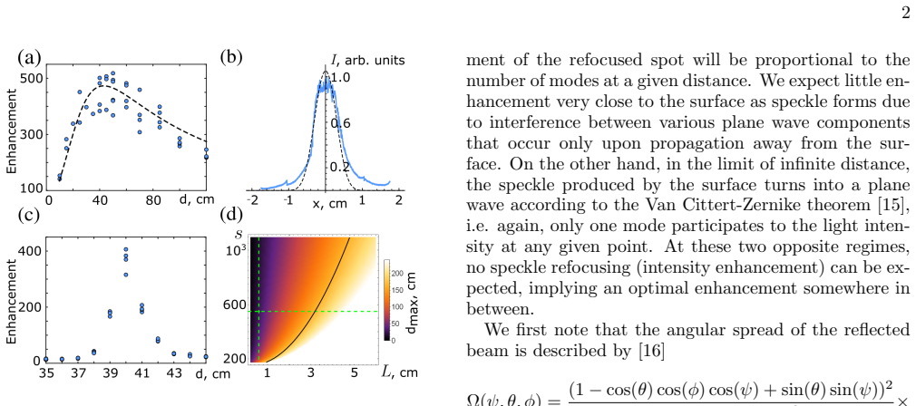
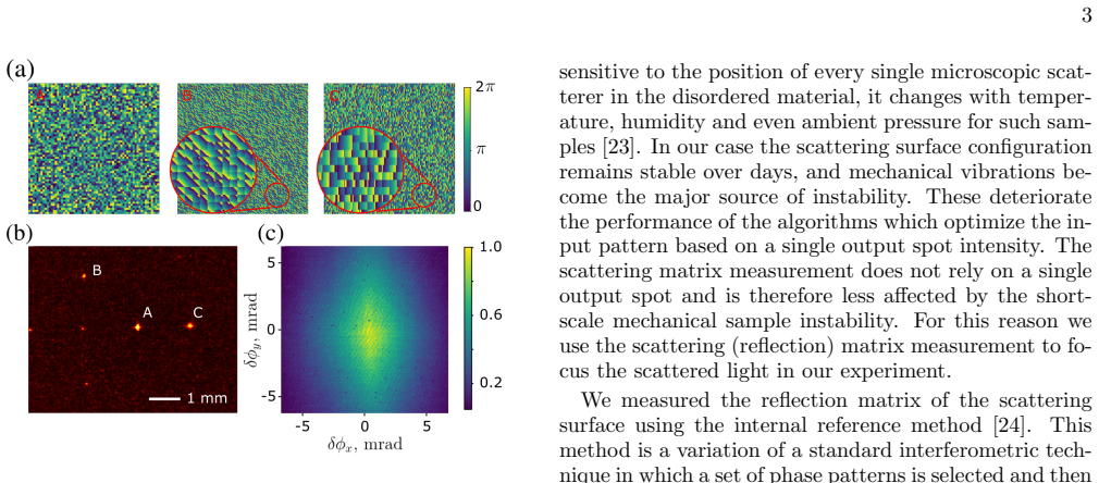
The load-bearing mechanism is the combination of three optical effects: wavefront shaping via the measured reflection matrix of the rough surface, which focuses scattered laser light into a bright spot; the speckle memory effect, which lets a phase gradient on the spatial light modulator translate that spot without re-measuring the surface; and time-of-flight gating, which separates photons reflected from the hidden object from the much stronger background returning from the wall. A theoretical model, Eq. (3), predicts an optimal focusing distance where the number of controllable speckle modes peaks, and the experiment operates at that distance (40 centimetres) and matches the predicted enhancement curve.
What would settle it
Repeat the imaging sequence with the hidden object in place and no camera ever placed at its location; if the focused spot cannot be formed from the measured reflection matrix and the memory-effect scan fades beyond a few millimetres, the practical claim of non-invasive sub-millimetre imaging fails.
Extended reading notes
Core claim
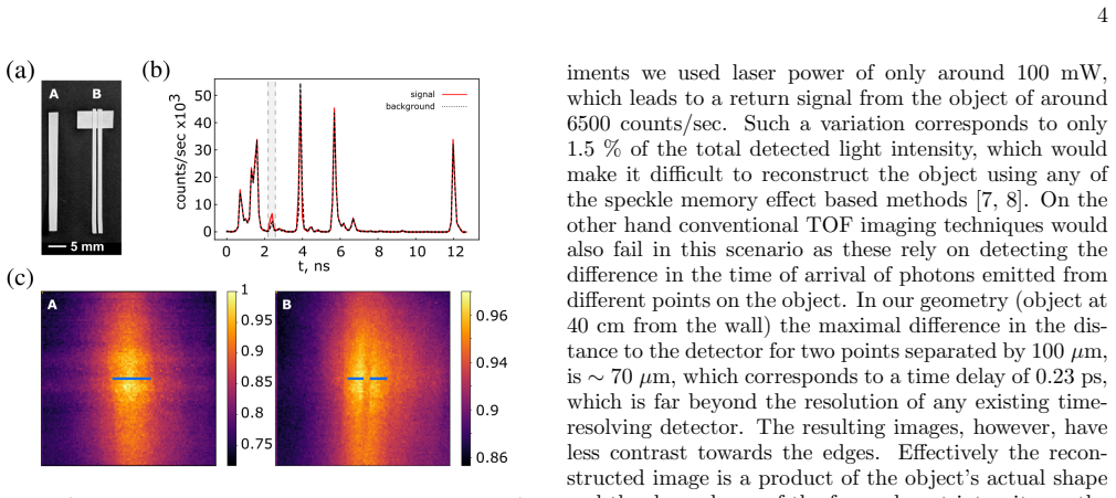
The central discovery is that combining coherent wavefront shaping, the speckle memory effect, and time-of-flight gating converts a scattering wall into a scanning virtual lens for the hidden region. A reflection matrix measured with the spatial light modulator creates a tight focus in the speckle field; a linear phase gradient applied to the modulator then translates that focus by several millimetres (and, in principle, about plus or minus 1 centimetre within the memory-effect range). Scanning the focus across the object and integrating the returned time-of-flight histogram only in a 0.5 nanosecond window around the object's arrival time suppresses background and yields a direct intensity picture. This produces images of objects a few millimetres across, with the resolution determined by the focused spot rather than by detector timing.
Load-bearing premise
The demonstrated method requires first placing a camera at the hidden object's position to measure the reflection matrix, and it assumes that matrix stays valid across the scanned region; if the hidden region is truly inaccessible or the scattering wall drifts, the imaging procedure breaks down.
Editorial extensions
If this is right
- If the method scales as claimed, non-line-of-sight imagers can resolve millimetre-scale features rather than the centimetre-scale features typical of time-of-flight reconstruction.
- Because the reconstruction is a direct intensity measurement, it avoids the heavy computational inversion used by time-of-flight non-line-of-sight algorithms.
- The focusing step's resolution can, in principle, approach the diffraction limit, so the ultimate resolution is set by how much laser energy can be concentrated into the spot.
- The temporal gate makes the method robust to strong background from the first wall reflection, enabling operation in geometries where memory-effect-only imaging fails.
- The measured memory-effect range of about plus or minus 1 centimetre implies a scan field of roughly 2 centimetres at 40 centimetres distance, matching the demonstrated field of view.
Reading between the lines
- A galvanometric mirror paired with the spatial light modulator could remove the phase-gradient limit and turn the demonstrated invasive calibration into a fully non-invasive scan behind an obstacle; the authors mention this possibility but did not implement it.
- If the calibration camera were replaced by an active beacon or retroreflector on the hidden side, the same technique could work in dynamic scenes where the wall's scattering properties drift slowly, provided occasional re-calibration.
- The coherent-focus-and-scan principle might transfer to other wavelengths or to ultrasound, where similar memory effects exist, though the optimal distance would shift with the scattering parameters.
- Resolution being tied to spot size suggests that adaptive optics could push the method toward diffraction-limited non-line-of-sight imaging, but only if the scattered field can be measured over a sufficiently large angular aperture.
Signed reviews
Editorial analysis
A structured set of objections, weighed in public.
Referee Report
Summary. The paper demonstrates a hybrid non-line-of-sight (NLOS) imaging approach that combines wavefront shaping, the speckle memory effect, and time-of-flight gating. Laser light is focused through a spatial light modulator onto a rough scattering wall; the reflected speckle is optimized (via reflection-matrix measurement) to produce a tight spot at a chosen position behind the wall; the spot is then scanned by adding linear phase gradients to the SLM pattern. Back-reflected light from a small object is collected by a SPAD and time-gated to reject background. The authors present a theoretical model for the optimal focusing distance, validate it with enhancement measurements, and show 100×100 scans of two small objects, claiming a spatial resolution below 1 mm. The main caveat, acknowledged in the conclusion, is that the initial focusing requires placing a camera at the hidden-object position, so the fully non-invasive version of the method was not achieved in this experiment.
Significance. If the claims are substantiated, the method would offer a meaningful advance: direct intensity-based NLOS imaging with sub-millimetre resolution, well beyond the centimetre-scale resolution of conventional time-of-flight NLOS techniques and without requiring a self-luminous hidden object as in earlier memory-effect correlation methods. The underlying physical idea is sound and the demonstration is conceptually clean, with a plausible analytic model and a useful temporal filtering step. The strength of the paper is that the imaging result is a direct measurement rather than an inverse reconstruction, and the authors are honest about the principal limitation. However, the significance is tempered by the invasive calibration step and by the absence of a direct resolution measurement, so the abstract's claims currently outrun the demonstrated evidence.
major comments (3)
- [Refocusing diffuse light for NLOS imaging; Conclusion] The calibration step is invasive: the authors write 'we put a camera at the supposed position of the object and perform an optimization by measuring the reflection matrix' and then 'replaced the camera with an object.' The Conclusion explicitly admits that 'fully non-invasive reconstruction was not achieved.' As a result, the experiment does not demonstrate coherent refocusing behind an actual obscuring obstacle, and the abstract's statement that the method 'refocus[es] the beam behind the obscuring obstacle' and 'open[s] the way to high-resolution NLOS imaging' overstates the demonstrated scope. Please either add an experiment with a non-invasive calibration (for example, using the memory effect to extend a reflection matrix measured on an accessible portion of the wall) or explicitly qualify the claims to the 'quasi-NLOS' geometry with access to the hidden position during calibration.
- [Results; Fig. 4] The claimed 'spatial resolution of less than 1 mm' is not directly evidenced. No resolution target, point-spread-function measurement, or edge-response measurement is presented, and no error bars or repeated scans are shown. The images in Fig. 4(c) are of objects of size 2.1 mm and 2.8 mm, and the text itself states that the reconstructed image is a product of the object shape and the spot-intensity envelope of Fig. 3(c). Please quantify the focused-spot size at the object plane, add a line-cut or resolution target, and report repeatability before the sub-millimetre claim can be accepted.
- [Results] The scan step is stated as '2.34 mrad (93 µm at 40 cm)'; these two numbers are inconsistent by a factor of 10, since 2.34 mrad at 40 cm corresponds to approximately 0.94 mm. Please correct the angular value or the displacement value, because the scan step and field of view directly support the resolution claim.
minor comments (4)
- [Fig. 2; Theoretical model] The statement that the fit in Fig. 2(a) has 'the only fitting parameter N0' is incomplete: s is also determined by a fit to the measured angular intensity distribution in Fig. 2(b). This two-step calibration should be described accurately, though it is not a flaw in the model itself.
- [Eq. (3)] Equation (3) would benefit from a definition of the normalization constant N0 and a statement of its dimensions; as written, the reader cannot easily verify the physical units of N(d).
- [Figs. 2 and 3] The enhancement and attenuation curves in Figs. 2(a), 2(c), and 3(c) are presented without error bars or multiple-trial statistics; adding measurement uncertainties would strengthen the quantitative claims.
- [Scanning the focused spot] There is a small typographical error: 'wile' should be 'while' in the sentence describing the memory-effect scan.
Circularity Check
Minor circularity: the optimal refocusing distance is read off a curve fitted to the same data, while the central imaging claim remains a direct measurement.
-
fitted input called prediction
[Theoretical model / Eq. (3) / Fig. 2(a)-2(d)]
"In Fig. 2(a) we also show the fit of the theoretical dependence N(d), Eq. (3) to our data, where the only fitting parameter is the normalisation constant N0, while s is determined by fitting Nθ, Eq. (2), which is proportional to the average intensity distribution of the scattered light, to an experimentally measured distribution, see Fig. 2(b)."
The model is presented as predicting an optimal refocusing distance dmax, but the two model parameters are fitted to the experimental data: s is fitted to the measured angular intensity distribution, and N0 is fitted to the enhancement-vs-distance curve whose maximum is then identified as dmax ≈ 40 cm. The subsequent experiments place the object at this same fitted distance, so the 'optimal distance' is not an independent prediction but a read-off from the calibration data. This is a fitted input called a prediction. It does not affect the central imaging result, which is obtained by directly scanning a calibrated focused spot and measuring the back-reflected gated intensity.
full rationale
The core imaging claim is self-contained: after calibration, the focused spot is scanned with memory-effect phase gradients and the back-reflected, time-gated intensity is measured directly, so the reconstructed image is not derived from the fitted model. The only reduction-to-inputs occurs in the theoretical-model section, where dmax is obtained by fitting Eq. (3) to the same enhancement-vs-distance data that is then used to choose the working distance. This is a non-central fitted-input-as-prediction, meriting a score of 2 rather than 0. The admitted inability to achieve a fully non-invasive calibration is an honest experimental limitation, not a circularity in the derivation.
Assumptions & free parameters
free parameters (4)
- N0 normalization =
approximately 10^5 (from Fig. 2a fit)
- Surface roughness ratio s =
approximately 550 (from Fig. 2b)
- Time gate window =
0.5 ns
- Scan step =
2.34 mrad (approximately 93 um at 40 cm)
assumptions (4)
- domain assumption The Van Cittert-Zernike theorem and the Bass-Fuks rough-surface scattering model Eq. (1) describe the angular distribution of light scattered by the brushed aluminium surface.
- domain assumption The scattering surface is stable over hours or days and the measured reflection matrix remains valid when the camera is replaced by the object.
- domain assumption The speckle memory effect holds over the scanned angular range, so adding a linear phase gradient shifts the focused spot without changing its shape.
- domain assumption The 0.5 ns time window isolates photons reflected from the object and rejects background from the first wall reflection.
Cite this review
Pith. "Pith review of Coherent control of light for non-line-of-sight imaging." pith.science (2026). https://pith.science/paper/SRR23LGU
@misc{pith2026190804094,
  author       = {Pith},
  title        = {Pith review of: Coherent control of light for non-line-of-sight imaging},
  year         = {2026},
  howpublished = {\url{https://pith.science/paper/SRR23LGU}},
  note         = {Machine review of arXiv:1908.04094}
}
read the original abstract
Non-line-of-sight (NLOS) imaging relies on collecting light that is rendered incoherent from the multiple scattering events and is then post-processed to provide an estimate of the hidden scene. Here we employ coherent phase control of the outgoing laser beam phase front so as to refocus the beam behind the obscuring obstacle and then use the speckle memory effect to scan the focused spot across the scene. The back-reflected light intensity provides a direct measurement of the scene with a signal-to-noise ratio that is greatly improved when measured using a temporally gated detector. A spatial resolution of less than 1 mm is demonstrated, opening the way to high-resolution NLOS imaging.
Figures

Figures from the paper (1 more)
Reference graph
Works this paper leans on
- [1]
-
[2]
Freund, Physica A: Statistical Mechanics and its Ap- plications 168, 49 (1990)
I. Freund, Physica A: Statistical Mechanics and its Ap- plications 168, 49 (1990)
work page 1990
-
[3]
A. Kirmani, T. Hutchison, J. Davis, and R. Raskar, in 2009 IEEE 12th International Conference on Computer Vision (IEEE, 2009) pp. 159–166
work page 2009
-
[4]
N. Naik, C. Barsi, A. Velten, and R. Raskar, J. Opt. Soc. Am. A 31, 957 (2014)
work page 2014
- [5]
- [6]
-
[7]
J. Bertolotti, E. G. Van Putten, C. Blum, A. Lagendijk, W. L. Vos, and A. P. Mosk, Nature 491, 232 (2012)
work page 2012
-
[8]
O. Katz, E. Small, and Y. Silberberg, Nature photonics 6, 549 (2012)
work page 2012
Show all 24 references
-
[9]
O. Katz, P. Heidmann, M. Fink, and S. Gigan, Nature photonics 8, 784 (2014)
2014
-
[10]
Gariepy, F
G. Gariepy, F. Tonolini, R. Henderson, J. Leach, and D. Faccio, Nature Photonics 10, 23 (2016)
2016
-
[11]
Sanzaro, P
M. Sanzaro, P. Gattari, F. Villa, A. Tosi, G. Croce, and F. Zappa, IEEE Journal of Selected Topics in Quantum Electronics 24, 1 (2017)
2017
-
[12]
I. M. Vellekoop and A. Mosk, Optics letters 32, 2309 (2007)
2007
-
[13]
Freund, M
I. Freund, M. Rosenbluh, and S. Feng, Phys. Rev. Lett. 61, 2328 (1988)
1988
-
[14]
S. Feng, C. Kane, P. A. Lee, and A. D. Stone, Phys. Rev. Lett. 61, 834 (1988)
1988
-
[15]
Goodman, Speckle Phenomena in Optics: Theory and Applications (Roberts & Company, 2007)
J. Goodman, Speckle Phenomena in Optics: Theory and Applications (Roberts & Company, 2007)
2007
-
[16]
F. G. Bass and I. M. Fuks, Wave scattering from statisti- cally rough surfaces (Pergamon Press, Oxford New York, 1979)
1979
-
[17]
I. M. Vellekoop, Optics express 23, 12189 (2015)
2015
-
[18]
I. M. Vellekoop and A. Mosk, Optics communications 281, 3071 (2008)
2008
-
[19]
D. B. Conkey, A. N. Brown, A. M. Caravaca-Aguirre, and R. Piestun, Opt. Express 20, 4840 (2012)
2012
-
[20]
L. Fang, H. Zuo, Z. Yang, X. Zhang, and L. Pang, Jour- nal of Applied Physics 124, 083104 (2018)
2018
-
[21]
C. W. J. Beenakker, Rev. Mod. Phys. 69, 731 (1997)
1997
-
[22]
S. M. Popoff, G. Lerosey, M. Fink, A. C. Boccara, and S. Gigan, New Journal of Physics 13, 123021 (2011)
2011
-
[23]
Albertazzi, M
A. Albertazzi, M. Viotti, F. Silva, C. Veiga, E. Barrera, M. Benedet, A. Fantin, and D. Willemann, in Optical Micro-and Nanometrology VII, Vol. 10678 (International Society for Optics and Photonics, 2018) p. 1067802
2018
-
[24]
Popoff, G
S. Popoff, G. Lerosey, R. Carminati, M. Fink, A. Boc- cara, and S. Gigan, Physical review letters 104, 100601 (2010)
2010
Reviewed August 14, 2026 · model on record in the stance chip above.
Discussion (0). Continue with ORCID to comment.