REVIEW 3 major objections 5 minor 47 references
A Building-Block Approach to State-Space Modeling of DC-DC Converter Systems
T0 review · 3 major / 5 minor · reviewed 2026-08-14 · deepseek-v4-flash
Pith's one-line read A complete DC-DC converter system model can be assembled from reusable building blocks by two standardized state-space connection operations, with no need to re-derive frequency-domain transfer functions when filters, loads, or control…
desk verdict A genuinely useful and mostly correct modular state-space composition method for DC-DC converters, but the closed-loop step misses D13 feedthrough corrections and needs a scope statement before it can be accepted. read the letter →
The pith
A machine-rendered reading of the paper's core claim, the machinery that carries it, and where it could break.
The reading
What carries the argument
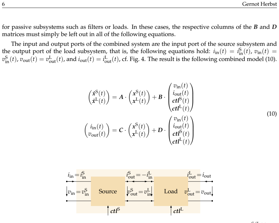
The central object is the generic two-port state-space model with inputs $v_{\mathrm{in}}(t)$, $i_{\mathrm{out}}(t)$, and $\mathrm{ctl}(t)$ and outputs $i_{\mathrm{in}}(t)$ and $v_{\mathrm{out}}(t)$: an inverse-hybrid (g-parameter) representation that treats input voltage and output current as independent variables. Two operations carry the argument: controller insertion, which augments the state vector and updates the $A$ matrix via $A_{\mathrm{CL}} = A_{\mathrm{OL}} - B_{\mathrm{OL}} K$ with $K$ choosing the controlled variable; and series connection, whose matrix formulas (13)-(15) eliminate the shared internal voltage and current between source and load. Their defining property is that each operation returns another model of the same two-port structure, which is what makes the frequency-domain extraction formulas collected in Table 2 valid at every modeling stage.
What would settle it
Take a converter model whose $D$ matrix has a nonzero $D_{13}$ or $D_{23}$ term, apply the closed-loop update $A_{\mathrm{CL}} = A_{\mathrm{OL}} - B_{\mathrm{OL}} K$ with $B$, $C$, $D$ unchanged, and compare the resulting output impedance or control-to-output gain with the exact model obtained by substituting the feedback law directly; any measurable discrepancy refutes the generality of the operation.
Extended reading notes
Core claim
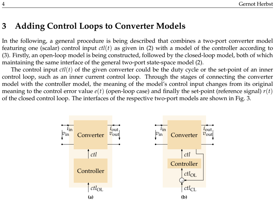
The central claim is that a two-port inverse-hybrid (g-parameter) state-space description, augmented with control inputs, is closed under the two operations needed to build practical converter systems: adding a controller and series-connecting a source with a load. Closing a loop is done by augmenting the state vector with the controller states, connecting the controller output to the converter control input, and updating the system matrix through $A_{\mathrm{CL}} = A_{\mathrm{OL}} - B_{\mathrm{OL}} K$, where $K$ selects the variable to feed back; $B$, $C$, and $D$ are left unchanged under the stated assumption that direct feedthrough from the control input to the controlled variable is negligible. Series-connecting two subsystems is done by eliminating the shared internal voltage and current with the coupling formulas (13)-(15), which produce a combined model of the same two-port form. Because the operations preserve the structure, one state-space model represents the whole system at every stage, and the transfer functions listed in Table 2 can be extracted from it at any point.
Load-bearing premise
The load-bearing premise is that the control input has no direct feedthrough to the measured controlled variable or to the input current, because the closed-loop construction updates only the system matrix $A$ while leaving $B$, $C$, and $D$ fixed; if either direct path is nonzero, the closed-loop model is only approximate.
Editorial extensions
If this is right
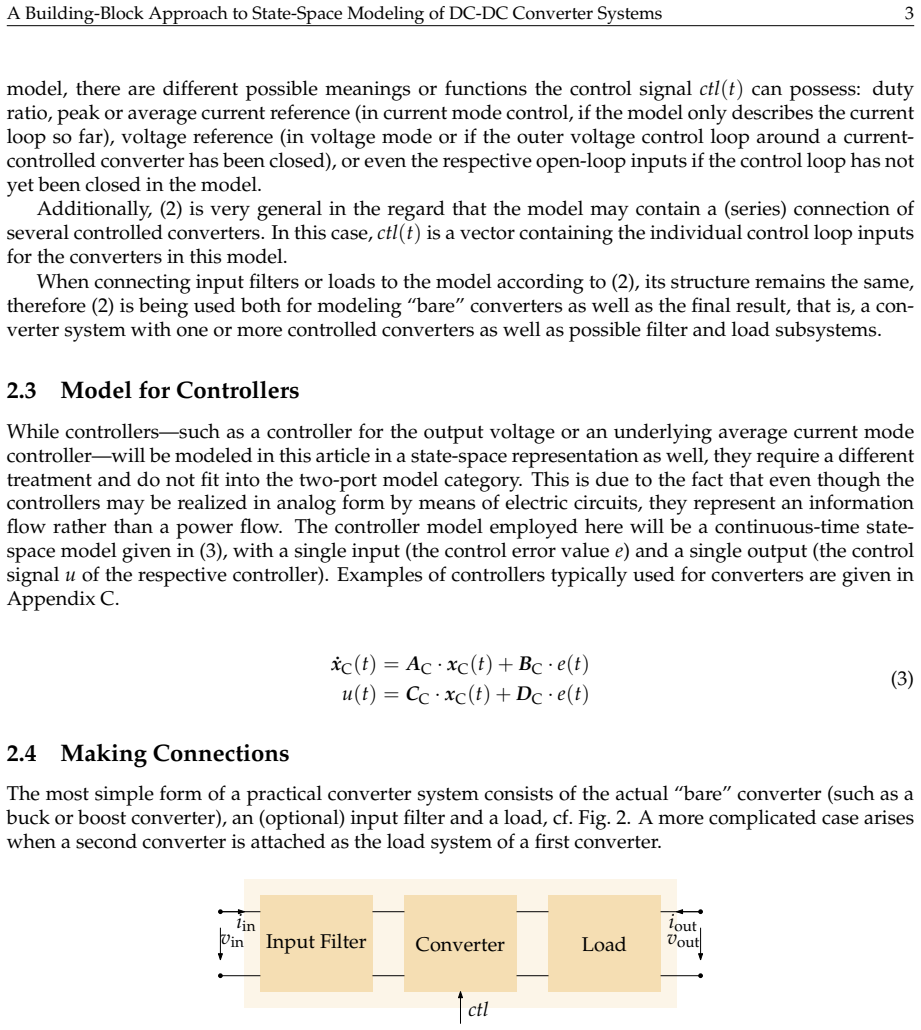
- After adding an input filter, a non-trivial load, or another converter stage, the existing model is updated by a connection operation instead of a full re-derivation of the state-space equations.
- Control loops can be closed one at a time, innermost first, with control-to-output and impedance transfer functions available after each step.
- The same connection rules apply to passive elements, controlled converters, and entire series-connected systems, so a model built once can be reused as a building block in a larger system.
- Because the operations preserve the two-port structure and linearity, all small-signal frequency-domain analyses remain valid at any modeling stage.
- Controller tuning can take source and load interactions into account directly, since the impedance seen at any port is extractable from the same model at any point in the assembly.
Reading between the lines
- Going beyond the paper, the series-connection formulas are pure matrix arithmetic, so the entire assembly procedure could be automated: a user would supply building-block matrices and a connection list, and a simple computer-algebra program would generate the full model and all Table 2 transfer functions.
- The paper's closed-loop update is exact only when the feedthrough terms $D_{13}$ and $D_{23}$ vanish; a natural generalization would be to substitute the feedback law algebraically into the output equations as well, covering converters with nonzero direct control feedthrough.
- Because the operations do not depend on the physical nature of the building blocks, the same two-port assembly rules could be tried on averaged models of other power-electronic subsystems, such as bidirectional converters or inverter input stages, as long as those models fit the same g-parameter state-space form.
Signed reviews
Editorial analysis
A structured set of objections, weighed in public.
Referee Report
Summary. This paper proposes a modular state-space modeling framework for DC-DC converter systems. It defines a generic two-port state-space model with an additional control input, a controller model, and two standardized connection operations: adding controllers and closing control loops (Section 3) and series-connecting two two-port subsystems (Section 4). In Section 6, three examples (a multiloop buck converter, a boost converter with input filter, and a cascaded boost-buck system) are built from these operations and validated against time-domain circuit simulations. The paper claims that control-oriented and impedance transfer functions can be extracted from the single resulting model at any modeling stage, open or closed loop, single converter or series connection of converters.
Significance. If correct, the framework would be a practically useful way to assemble and maintain converter system models without re-deriving state-space equations. The series-connection derivation leading to Equations (13)–(15) is algebraically sound, and the examples are validated against independent circuit simulations with no fitted parameters, which is a real strength. However, the control-loop operation in Section 3 is mathematically incomplete for the general controller and converter models stated, which undermines the claim that impedance transfer functions can be extracted after loop closure in all cases. Since the main contribution is the generality of the two connection operations, this gap is load-bearing and needs to be fixed before the paper can be accepted.
major comments (3)
- [Section 3, Eq. (5)] The open-loop model is incomplete. Substituting the controller output u(t)=CC xC(t)+DC e(t) into the two-port model (2) gives iin = C1 x + D13(CC xC + DC e) + D11 vin + D12 iout and vout = C2 x + D23(CC xC + DC e) + D21 vin + D22 iout. Therefore COL in (5) should be [C1, D13 CC; C2, D23 CC], not [C1, 0; C2, 0] as printed. As written, the open-loop model drops the contribution of the controller states to both outputs whenever D13 or D23 is nonzero, which occurs for buck-type converters where iin depends on the duty cycle (D13 = IL ≠ 0). This affects any input-current or input-admittance transfer function extracted from the open-loop model.
- [Section 3, Eqs. (6) and (8)] The closed-loop construction is also incomplete. If the feedback variable is the output voltage, the error is e = r − vout with vout = C2 x + D21 vin + D22 iout + D23 ctl, not e = r − C2 x unless D21 = D22 = D23 = 0. The K-matrix choice in (8) only feeds back C2 x. Consequently, even with the paper's assumption D23 ≈ 0, the closed-loop state and output equations miss the terms −BOL,3 D21 vin, −BOL,3 D22 iout, and the corresponding DOL corrections. The sentence 'The B, C, D matrices of the open-loop and closed-loop case are identical' is thus correct only under additional unstated conditions (e.g., D13 = D21 = D22 = 0 and DC = 0). Since Table 2 promises extraction of Zout, Yin, and other transfer functions at any modeling stage, this is a load-bearing gap rather than a cosmetic one.
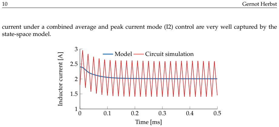
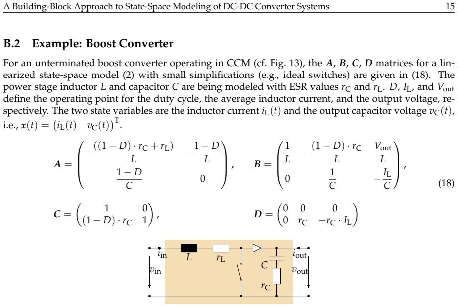
- [Section 6 and Appendix C] The numerical examples do not exercise the problematic terms in the general loop-closing operation. All controller models in Appendix C have DC = 0, and the boost model in (18) has D13 = 0; the buck converter is cited from Reference [27] rather than given, so the reader cannot check whether D13 is nonzero. The time-domain validations compare inductor current and output voltage (state variables or outputs with small feedthrough), but never the input current iin after loop closure. Thus the examples are consistent with a restricted case and do not demonstrate the claimed generality. I recommend adding a benchmark with D13 ≠ 0 and/or DC ≠ 0, or explicitly narrowing the scope of Section 3.
minor comments (5)
- [References] Many DOIs in the reference list appear garbled (e.g., 'doi:1A.11AJ/...' in [1], [2], and others); these should be corrected to the standard DOI format.
- [Section 4, Eq. (15)] In the line defining the abbreviations, the term 'D1 11L' appears to be a typo for DL11; the notation should be fixed.
- [Section 6.1] The superscript notation for 'I2 control' is inconsistent (sometimes rendered as 'I2' and sometimes as 'I²'); please standardize.
- [Figure 8] The caption states that solid and dashed lines correspond to 'with input filter' and 'without input filter', but the figure legend is not explicit; please make the line styles unambiguous in the figure itself.
- [General terminology] The abstract uses 'cascaded converters' while the main text predominantly uses 'series connections of converters'; consider unifying the terminology.
Circularity Check
No significant circularity found: the connection operations are derived algebraically from the stated two-port models and validated against independent circuit simulations.
full rationale
The paper's central contribution is a set of standardized operations for connecting two-port state-space models. The series-connection formulas in Section 4 are obtained by direct algebraic substitution of the terminal constraints vL_in = vS_out and iS_out = -iL_in into the source and load state equations, with no target result assumed and no fitted parameters. The closed-loop construction in Section 3 uses the standard state-feedback expression ACL = AOL - BOL*K with B, C, D unchanged; this is a stated algebraic choice rather than a circular one. The paper explicitly acknowledges the assumption D23 ≈ 0 for voltage-mode control, and while the treatment of D13 feedthrough is arguably incomplete as a general procedure, that is a correctness limitation, not circularity. The validation examples compare the assembled state-space models against time-domain circuit simulations without adjusting any model parameters to match those simulations, so the predictions are not forced by fitting. External converter models from the literature are used as building blocks as claimed, and the paper does not rename any known result as a new derivation. Therefore there are no load-bearing steps that reduce to their own inputs.
Assumptions & free parameters
assumptions (5)
- domain assumption All converter and filter subsystems can be represented by linear time-invariant state-space two-port models in inverse-hybrid (g-parameter) form with inputs vin, iout, ctl and outputs iin, vout.
- domain assumption The series connection is well-posed, meaning the scalar 1 + D11^L * D22^S is nonzero.
- domain assumption Direct feedthrough from the control input to the controlled variable is negligible when closing a loop.
- domain assumption Controllers are SISO linear continuous-time state-space systems with a single error input and a single control output.
- domain assumption The converter building blocks imported from cited references, such as the PCM buck model from reference [27] and two-port models from references [30] and [34], are valid averaged small-signal models at the stated operating points.
Cite this review
Pith. "Pith review of A Building-Block Approach to State-Space Modeling of DC-DC Converter Systems." pith.science (2026). https://pith.science/paper/TN5MVRXW
@misc{pith2026190804594,
  author       = {Pith},
  title        = {Pith review of: A Building-Block Approach to State-Space Modeling of DC-DC Converter Systems},
  year         = {2026},
  howpublished = {\url{https://pith.science/paper/TN5MVRXW}},
  note         = {Machine review of arXiv:1908.04594}
}
read the original abstract
Small-signal models of DC-DC converters are often based on a state-space averaging approach, from which both control-oriented and other frequency-domain characteristics, such as input or output impedance, can be derived. Updating these models when extending the converter by filters or non-trivial loads, or adding control loops, can become a tedious task, however. To simplify this potentially error-prone process, a modular modeling approach is being proposed in this article. It consists of small state-space models for certain building blocks of a converter system on the one hand, and standardized operations for connecting these subsystem models to an overall converter system model on the other hand. The resulting state-space system model builds upon a two-port converter description and allows the extraction of control-oriented and impedance characteristics at any modeling stage, be it open loop or closed loop, single converter or series connections of converters. The ease of creating more complex models enabled by the proposed approach is also demonstrated with examples comprising multiple control loops or cascaded converters.
Figures

Figures from the paper (10 more)


Reference graph
Works this paper leans on
-
[27]
Sean C. Smithson and Sheldon S. Williamson. A unified state-space model of constant-frequency current-mode controlled power converters in continuous conduction mode. IEEE Transactions on Industrial Electronics, 62(7):4514–4524, 2015. doi:1A.11AJ/eIE.CA15.CE1C51E
work page 2015
-
[1]
Reza Ahmadi and Mehdi Ferdowsi. Controller design method for a cascaded converter system comprised of two DC-DC converters considering the effects of mutual interactions. In2012 Twenty- Seventh Annual IEEE Applied Power Electronics Conference and Exposition (APEC) , pages 1838–1844,
-
[2]
Reza Ahmadi and Mehdi Ferdowsi. Modeling closed-loop input and output impedances of DC-DC power converters operating inside DC distribution systems. In 2014 IEEE Applied Power Electronics Conference and Exposition (APEC), pages 1131–1138, 2014. doi:1A.11AJ/RPET.CA1E.GIADEEJ
work page 2014
-
[3]
Reza Ahmadi, Darren Paschedag, and Mehdi Ferdowsi. Analyzing stability issues in a cascaded converter system comprised of two voltage-mode controlled DC-DC converters. In 2011 Twenty- Sixth Annual IEEE Applied Power Electronics Conference and Exposition (APEC), pages 1769–1775, 2011. doi:1A.11AJ/RPET.CA11.57EEIDG
work page 2011
-
[4]
Behavioral modeling for parallel- and cascade-connected DC-DC converters
Husan Ali, Xiancheng Zheng, Haider Zaman, Huamei Liu, and Xiaohua Wu. Behavioral modeling for parallel- and cascade-connected DC-DC converters. Journal of Circuits, Systems and Computers , 28(4), 2019. doi:1A.11EC/dAC1I1CGG1J5AA5IA
work page 2019
-
[5]
System-level black-box DC-to- DC converter models
Luis Arnedo, Rolando Burgos, Dushan Boroyevich, and Fred Wang. System-level black-box DC-to- DC converter models. In 2009 Twenty-Fourth Annual IEEE Applied Power Electronics Conference and Exposition (APEC), pages 1476–1481, 2009. doi:1A.11AJ/RPET.CAAJ.EIACIG1
work page 2009
-
[6]
Designing Control Loops for Linear and Switching Power Supplies: A Tutorial Guide
Christophe Basso. Designing Control Loops for Linear and Switching Power Supplies: A Tutorial Guide . Artech House, Boston, 2012
work page 2012
-
[7]
Switch-Mode Power Supplies: SPICE Simulations and Practical Designs
Christophe Basso. Switch-Mode Power Supplies: SPICE Simulations and Practical Designs . McGraw- Hill, New York, NY, USA, 2 edition, 2014
work page 2014
Show all 47 references
-
[8]
Why ideal constant power loads are not the worst case condition from a control standpoint
Marco Cupelli, Lin Zhu, and Antonello Monti. Why ideal constant power loads are not the worst case condition from a control standpoint. IEEE Transactions on Smart Grid , 6(6):2596–2606, 2015. doi:1A.11AJ/edG.CA1E.CDG1GDA
2015
-
[9]
Lee, and Dong Dong
Igor Cvetkovic, Dushan Boroyevich, Paolo Mattavelli, Fred C. Lee, and Dong Dong. Untermi- nated small-signal behavioral model of DC-DC converters. IEEE Transactions on Power Electronics, 28(4):1870–1879, 2013. doi:1A.11AJ/ePEL.CA1C.CC15A5G
2013
-
[10]
Kazimierczuk
Dariusz Czarkowski and Marian K. Kazimierczuk. Energy-conservation approach to modeling PWM DC-DC converters. IEEE Transactions on Aerospace and Electronic Systems , 29(3):1059–1063,
-
[11]
Numerical state-space average-value modeling of PWM DC-DC converters operating in DCM and CCM
Ali Davoudi, Juri Jatskevich, and Tom De Rybel. Numerical state-space average-value modeling of PWM DC-DC converters operating in DCM and CCM. IEEE Transactions on Power Electronics , 21(4):1003–1012, 2006. doi:1A.11AJ/ePEL.CAAG.I7GIEI
2006
-
[12]
A black-box mod- eling approach for DC nanogrids
Airan Francés, Rafael Asensi, Oscar García, Roberto Prieto, and Javier Uceda. A black-box mod- eling approach for DC nanogrids. In 2016 IEEE Applied Power Electronics Conference and Exposition (APEC), pages 1624–1631, 2016. doi:1A.11AJ/RPET.CA1G.7EGIAIE
2016
-
[13]
How to model a DC microgrid: Towards an automated solution
Airan Francés, Rafael Asensi, Oscar García, Roberto Prieto, and Javier Uceda. How to model a DC microgrid: Towards an automated solution. In 2017 IEEE Second International Conference on DC Microgrids (ICDCM), pages 609–616, 2017. doi:1A.11AJ/ITDTM.CA17.IAA111A
2017
-
[14]
Modeling elec- tronic power converters in smart DC microgrids—An overview
Airan Francés, Rafael Asensi, Oscar García, Roberto Prieto, and Javier Uceda. Modeling elec- tronic power converters in smart DC microgrids—An overview. IEEE Transactions on Smart Grid , 9(6):6274–6287, 2018. doi:1A.11AJ/edG.CA17.C7A7DE5
2018
-
[15]
Power exchange among microgrids using modular-isolated bidirectional DC-DC converter
Reza Haghmaram, Farzad Sedaghati, and Reza Ghafarpour. Power exchange among microgrids using modular-isolated bidirectional DC-DC converter. Electrical Engineering, 99(1):441–454, 2017. doi:1A.1AA7/sAACAC-A1G-AED7-7 . A Building-Block Approach to State-Space Modeling of DC-DC ...
2017
-
[16]
Synthesis of canonical elements for power processing in DC distribution systems using cascaded converters and sliding-mode control
Reham Haroun, Angel Cid-Pastor, Abdelali El Aroudi, and Luis Martíinez-Salamero. Synthesis of canonical elements for power processing in DC distribution systems using cascaded converters and sliding-mode control. IEEE Transactions on Power Electronics, 29(3):1366–1381, 2014. d...
2014
-
[17]
Hung, and R
Siyu He, John Y. Hung, and R. Mark Nelms. Small-signal modeling of I2 average current mode control. IEEE Transactions on Power Electronics , 31(5):3849–3858, 2016. doi:1A.11AJ/ePEL.CA15. CE5JJ1C
2016
-
[18]
A novel stability analysis method based on Floquet theory for cascaded DC-DC converters system
Hong Li, Jianing Shang, Xiaojie You, Trillion Zheng, Bo Zhang, and Jinhu Lü. A novel stability analysis method based on Floquet theory for cascaded DC-DC converters system. In2015 IEEE En- ergy Conversion Congress and Exposition (ECCE) , pages 2679–2683, 2015. doi:1A.11AJ/ETTE...
2015
-
[19]
Analysis, simulation and experimental evaluation of constant-frequency trailing-edge-modulated I2 average current-mode control
Ruqi Li, Kan Seto, Jessica Kiefer, and Sean Li. Analysis, simulation and experimental evaluation of constant-frequency trailing-edge-modulated I2 average current-mode control. In 2016 IEEE 8th International Power Electronics and Motion Control Conference (IPEMC-ECCE Asia) , pa...
2016
-
[20]
Two-port characterization of PWM voltage regulators at low frequencies.IEEE Transactions on Industrial Electronics, 35(3):444–450, 1988
Piero Giuseppe Maranesi, Valerio Tavazzi, and Vincenzo Varoli. Two-port characterization of PWM voltage regulators at low frequencies.IEEE Transactions on Industrial Electronics, 35(3):444–450, 1988. doi:1A.11AJ/E1.D1CA
1988
-
[21]
Some new results on the averaging theory approach for the analy- sis of power electronic converters.IEEE Transactions on Industrial Electronics, 65(12):9367–9377, 2018
Santolo Meo and Luisa Toscano. Some new results on the averaging theory approach for the analy- sis of power electronic converters.IEEE Transactions on Industrial Electronics, 65(12):9367–9377, 2018. doi:1A.11AJ/eIE.CA1I.CIC1GCA
2018
-
[22]
A general unified approach to modelling switching- converter power stages
Robert David Middlebrook and Slobodan ´Cuk. A general unified approach to modelling switching- converter power stages. In 1976 IEEE Power Electronics Specialists Conference , pages 18–34, 1976. doi:1A.11AJ/PEdT.1J7G.7A7CIJ5
1976
-
[23]
Stability analysis of cascaded DC-DC power electronic system
Veerachary Mummadi and Bala Sudhakar Singamaneni. Stability analysis of cascaded DC-DC power electronic system. IEEJ Transactions on Electrical and Electronic Engineering, 4(6):763–770, 2009. doi:1A.1AAC/tee.CAE7I
2009
-
[24]
Petrovi´ c and Aleksandar Ž
Trajko B. Petrovi´ c and Aleksandar Ž. Raki´ c. Linear robust approach to DC/DC converter modeling—I: Deterministic switching. Electrical Engineering, 86(5):267–273, 2004. doi:1A.1AA7/ sAACAC-AAD-AC1A-G
2004
-
[25]
Control design and loop gain analysis of DC-to- DC converters intended for general load subsystems
Syam Kumar Pidaparthy and Byungcho Choi. Control design and loop gain analysis of DC-to- DC converters intended for general load subsystems. Mathematical Problems in Engineering , 2015. doi:1A.1155/CA15/ECGD15
2015
-
[26]
Modeling, control, and implementation of DC-DC converters for variable frequency opera- tion
Robert Priewasser, Matteo Agostinelli, Christoph Unterrieder, Stefano Marsili, and Mario Hue- mer. Modeling, control, and implementation of DC-DC converters for variable frequency opera- tion. IEEE Transactions on Power Electronics, 29(1):287–301, 2014. doi:1A.11AJ/ePEL.CA1D.CCEI751
2014
-
[28]
Mitchell, Matthew F
Jian Sun, Daniel M. Mitchell, Matthew F. Greuel, and Philip T. Krein. Averaged modeling of PWM converters operating in discontinuous conduction mode. IEEE Transactions on Power Electronics , 16(4):482–492, 2001. doi:1A.11AJ/GD.JD1A5C
2001
-
[29]
Unified average and small-signal modeling of direct-on-time control
Teuvo Suntio. Unified average and small-signal modeling of direct-on-time control. IEEE Transac- tions on Industrial Electronics, 53(1):287–295, 2006. doi:1A.11AJ/eIE.CAA5.IGCCC1
2006
-
[30]
Dynamic Profile of Switched-Mode Converter: Modeling, Analysis and Control
Teuvo Suntio. Dynamic Profile of Switched-Mode Converter: Modeling, Analysis and Control . Wiley- VCH, Weinheim, Germany, 2009
2009
-
[31]
Dynamic modeling and analysis of PCM-controlled DCM-operating buck converters—a reexamination
Teuvo Suntio. Dynamic modeling and analysis of PCM-controlled DCM-operating buck converters—a reexamination. Energies, 11(5), 2018. doi:1A.DDJA/en11A51CG7. 18 Gernot Herbst
2018
-
[32]
On dynamic modeling of PCM-controlled converters—buck converter as an ex- ample
Teuvo Suntio. On dynamic modeling of PCM-controlled converters—buck converter as an ex- ample. IEEE Transactions on Power Electronics , 33(6):5502–5518, 2018. doi:1A.11AJ/ePEL.CA17. C7D7G7J
2018
-
[33]
Modeling and analysis of a PCM-controlled boost converter designed to operate in DCM
Teuvo Suntio. Modeling and analysis of a PCM-controlled boost converter designed to operate in DCM. Energies, 12(1), 2019. doi:1A.DDJA/en1CA1AAAE
2019
-
[34]
Wiley-VCH, Weinheim, Germany, 2017
Teuvo Suntio, Tuomas Messo, and Joonas Puukko.Power Electronic Converters: Dynamics and Control in Conventional and Renewable Energy Applications. Wiley-VCH, Weinheim, Germany, 2017
2017
-
[35]
Dynamic char- acterization of power electronic interfaces
Teuvo Suntio, Jukka Viinamäki, Juha Jokipii, Tuomas Messo, and Alon Kuperman. Dynamic char- acterization of power electronic interfaces. IEEE Journal of Emerging and Selected Topics in Power Electronics, 2(4):949–961, 2014. doi:1A.11AJ/JEdePE.CA1E.CD1D7AE
2014
-
[36]
A comparison of stability analysis of constant power load with detailed model in DC microgrids
Hesamoddin Mazaheri Tehrani, Airan Francés, Rafael Asensi, and Javier Uceda. A comparison of stability analysis of constant power load with detailed model in DC microgrids. In 2018 7th In- ternational Conference on Renewable Energy Research and Applications (ICRERA), pages 487...
2018
-
[37]
Optimum feedback amplifier design for control systems
Harlan Dean Venable. Optimum feedback amplifier design for control systems. Venable Technical Paper #3, Venable Industries, Austin, TX
-
[38]
Effect of control method on impedance-based interactions in a buck converter.IEEE Transactions on Power Electronics, 28(11):5311–5322, 2013
Sanna Kaarina Vesti, Teuvo Suntio, Jesús Ángel Oliver, Roberto Prieto, and José Antonio Cobos. Effect of control method on impedance-based interactions in a buck converter.IEEE Transactions on Power Electronics, 28(11):5311–5322, 2013. doi:1A.11AJ/ePEL.CA1D.CCE7ECC
2013
-
[39]
Simplified analysis of PWM converters using model of PWM switch
Vatché Vorpérian. Simplified analysis of PWM converters using model of PWM switch. part I: Continuous conduction mode. IEEE Transactions on Aerospace and Electronic Systems, 26(3):490–496,
-
[40]
Modeling PWM DC/DC converters out of basic converter units
Tasi-Fu Wu and Yu-Kai Chen. Modeling PWM DC/DC converters out of basic converter units. IEEE Transactions on Power Electronics, 13(5):870–881, 1998. doi:1A.11AJ/GD.71CCJE
1998
-
[41]
Lee, Paolo Mattavelli, and Pei-Hsin Liu
Yingyi Yan, Fred C. Lee, Paolo Mattavelli, and Pei-Hsin Liu. I2 average current mode control for switching converters. IEEE Transactions on Power Electronics, 29(4):2027–2036, 2014. doi:1A.11AJ/ ePEL.CA1D.CCG5DI1
2027
-
[42]
Dynamic properties of interconnected power systems - a system theoretic approach
Kai Zenger, Ali Altowati, and Teuvo Suntio. Dynamic properties of interconnected power systems - a system theoretic approach. In 2006 1st IEEE Conference on Industrial Electronics and Applications , pages 1–6, 2006. doi:1A.11AJ/ITIER.CAAG.C571J7
2006
-
[43]
A generalized model of nonisolated multi- phase DC-DC converter based on novel switching period averaging method
Difu Zhan, Li Wei, Yicheng Zhang, and Yongtao Yao. A generalized model of nonisolated multi- phase DC-DC converter based on novel switching period averaging method. IEEE Transactions on Power Electronics, 30(9):5181–5191, 2015. doi:1A.11AJ/ePEL.CA1E.CDG1A1J
2015
-
[1990]
doi:1A.11AJ/7.1AG1CG
-
[1993]
doi:1A.11AJ/7.CCAJ55
-
[2012]
doi:1A.11AJ/RPET.CA1C.G1GGA7C
-
[2016]
doi:1A.11AJ/IPEMT.CA1G.751CG17
Reviewed August 14, 2026 · model on record in the stance chip above.
Discussion (0). Continue with ORCID to comment.