REVIEW 3 major objections 5 minor 21 references
Non-reciprocity using quadrature-phase time-varying slab resonators
T0 review · 3 major / 5 minor · reviewed 2026-08-14 · deepseek-v4-flash
Pith's one-line read This paper claims that two spatially uniform, sinusoidally time-modulated Fabry-Perot slabs with a quadrature phase difference can produce near-total non-reciprocity at the incident frequency.
desk verdict Plausible and worth reviewing, but the headline non-reciprocity is verified only by the same analytical solver that produces it, while the FDTD check runs in a very different regime. read the letter →
The pith
A machine-rendered reading of the paper's core claim, the machinery that carries it, and where it could break.
The reading
What carries the argument
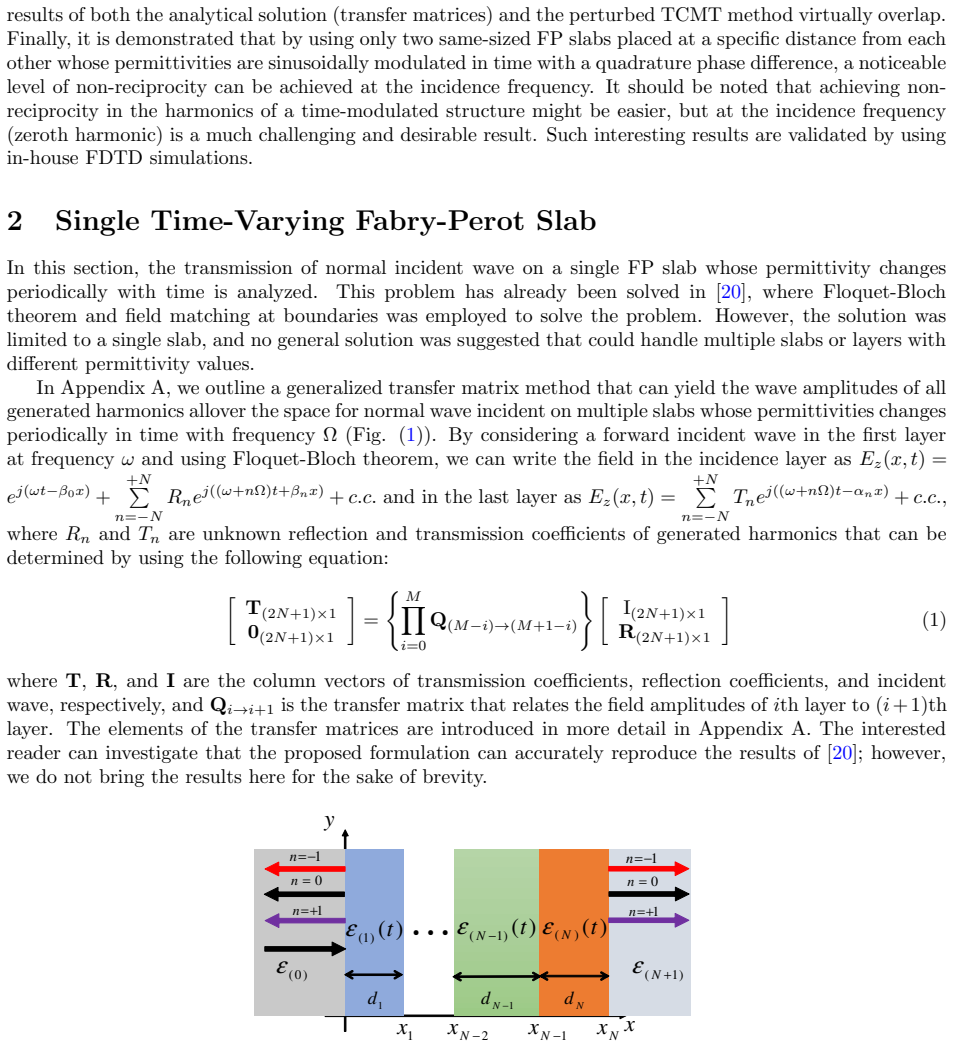
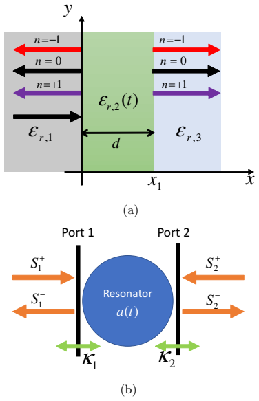
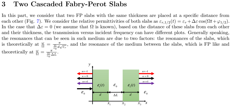
The argument is carried by three tools. A generalized transfer matrix built on Floquet-Bloch harmonics relates all sideband amplitudes across any stack of time-periodic slabs. A time-perturbed temporal coupled-mode theory replaces each slab system by resonant modes with time-modulated resonance frequencies and couplings; for two coupled slabs it keeps two supermodes split by $\Delta\omega_0$. Tuning $\Omega=2\Delta\omega_0$ makes the sinusoidal time modulation resonate with the mode splitting, and the $\pi/2$ phase difference rotates the perturbation asymmetrically so that forward and reverse transmissions acquire different complex amplitudes. The fitted parameters $z_0$ and $w_0$ are the direction-sensitive terms responsible for the effect.
What would settle it
Measure the zeroth-harmonic transmission from both sides of two identical slabs with the paper's $d$, $\Delta L$, and modulation phase difference $\pi/2$, sweeping the incident frequency near the coupled resonances: if the forward and reverse transmission spectra coincide, the proposed non-reciprocity is absent. A second check: replace $\pi/2$ by $0$; the paper predicts reciprocity, so any observed asymmetry there would also invalidate the mechanism.
Extended reading notes
Core claim
The central discovery is that two spatially uniform time-modulated Fabry-Perot slabs, whose permittivities oscillate as $\varepsilon_r(t)=\varepsilon_r+\Delta\varepsilon\cos(\Omega t+\phi_{1/2})$ with $\phi_2-\phi_1=\pi/2$, yield strongly asymmetric transmission at the incidence frequency $\omega$: the forward direction transmits near unity while the reverse direction transmits near zero. The effect appears when the modulation frequency $\Omega$ equals the splitting between the even and odd supermodes of the coupled slabs, and it is absent for equal phases or for a single slab. Physically, the quadrature phase makes the time-perturbation coefficients of the two supermodes differ for the two incidence directions, so the reverse path acquires an additional coupling channel that the forward path does not.
Load-bearing premise
The result holds only if each slab's permittivity is uniform in space and oscillates as a perfect sinusoid with an exact $\pi/2$ phase lag between the two slabs; any spatial gradient in the modulation effectively introduces a hidden travelling-wave component and changes the balance.
Editorial extensions
If this is right
- Microwave isolators, gyrators, and circulators could be built without a travelling-wave pump or any spatial gradient in the modulating signal, removing a major implementation obstacle.
- The effect delivers non-reciprocity at the incidence frequency itself, the zeroth harmonic, which the paper notes is harder and more desirable than achieving asymmetry only in generated sidebands.
- The generalized transfer-matrix method gives an exact harmonic-by-harmonic description for arbitrary stacks of time-periodic slabs, so the same analysis tool applies to other multilayer time-varying designs.
- The perturbed temporal coupled-mode theory reproduces both the single-slab and coupled-slab transmission spectra, giving a compact design rule: choose slab thickness, gap, and modulation frequency so that the modulation locks to the mode splitting.
- The FDTD validation at higher modulation amplitude confirms the predicted harmonic amplitudes in both propagation directions, so the non-reciprocity is not an artifact of the analytical truncation.
Reading between the lines
- The same quadrature-phase argument should transfer to any pair of evanescently coupled resonators with split modes, such as rings, microdisks, or photonic-crystal cavities, because only the existence of two split modes and a time-modulated coupling is used.
- The paper leaves oblique incidence and polarization untreated; for p-polarized waves the layer matrices gain a magnetic-field component, and the quadrature condition may shift with angle.
- Because the effect lives near the split-mode frequency and needs $\Omega$ exactly at the splitting, it is narrowband; cascading several phase-staggered pairs might widen the isolation window while keeping pure time-only modulation.
- The paper does not quantify sensitivity to modulation-phase error or amplitude mismatch, but the fitted coefficients imply the contrast degrades continuously as the phase difference moves away from $\pi/2$.
Signed reviews
Editorial analysis
A structured set of objections, weighed in public.
Referee Report
Summary. The manuscript analyzes normal-incidence propagation through one-dimensional slabs whose permittivities are modulated periodically in time. It develops a generalized Floquet transfer-matrix method that gives all harmonic amplitudes in multilayer stacks, and it introduces a phenomenologically perturbed temporal coupled-mode theory (TCMT) whose coefficients are fitted to the transfer-matrix results. The central claim is that two identical Fabry-Perot slabs modulated sinusoidally with a quadrature phase difference produce strong non-reciprocity in transmission at the incidence frequency, with near-unity contrast for the chosen parameters. An in-house FDTD code is used to check the transfer-matrix method at one high-modulation-depth, low-frequency operating point, and the TCMT is fitted to the exact solution in several single-slab and two-slab configurations.
Significance. If the headline result holds, the paper identifies a conceptually simple configuration—two time-modulated slab resonators with a fixed phase offset—that yields carrier-frequency non-reciprocity without a travelling-wave pump. The generalized transfer-matrix method itself is a useful extension of single-slab treatments to multilayers and appears mathematically sound. The TCMT fits provide a compact design description, although their explanatory power is limited by construction. The FDTD check at one extreme parameter set is a genuine effort at independent validation, but its scope does not cover the regime in which the main quantitative claim is made.
major comments (3)
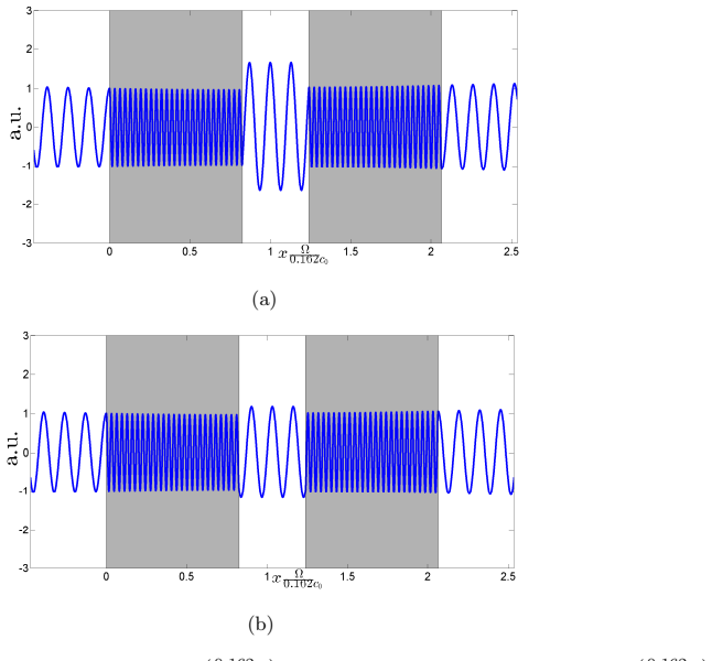
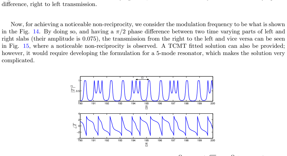
- [Section 4, Fig. 16] The independent FDTD validation is run at Δε=4 and ω/Ω=3.86, whereas the headline incidence-frequency contrast is demonstrated at Δε=0.075 and ω/Ω≈193 (Fig. 15). These are different regimes by roughly a factor of 50 in both modulation depth and normalized frequency. The FDTD check therefore validates the transfer-matrix solver for deep modulation at low frequency, but it does not verify the near-unity contrast at the incidence frequency claimed for the weakly modulated, high-frequency resonance. No convergence data are provided for the harmonic truncation N in Appendix A or for the FDTD discretization. Please add an independent check at or near the headline parameters, or supply a convergence study and a clear statement of accuracy in that regime; without this, the central quantitative claim rests on a single unverified solver.
- [Abstract; Introduction; Section 4] The claim that the approach avoids spatio-temporal modulation is overstated. The two slabs are modulated with phases φ1=0 and φ2=π/2, so the overall permittivity is a piecewise-constant space-time function: ε(x,t) varies in x through the different modulation phases of the two slabs. This is a (stepped) spatio-temporal modulation, even though each slab is spatially uniform. The novelty of the proposal is better described as using a discrete modulation-phase step rather than a travelling wave, and the text should be revised to say so explicitly in the Introduction and Conclusion.
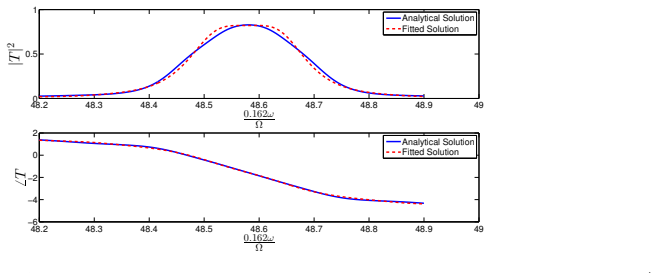
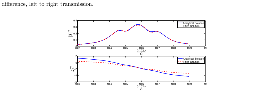
- [Sections 2.1, 3, and Table 1] The TCMT model is fitted rather than derived. The stated check in Section 2.1 that the +1 harmonic from Eq. (10b) agrees with the analytical result is a consistency test of the three-harmonic truncation, but the perturbation parameters themselves are obtained by fitting to the exact transfer-matrix solution. Similarly, the coefficients z_n and w_n in Table 1 are fitted to the analytical transmission at the pole frequencies, so the statement in Section 4 that the difference between z_0, w_0 for left-to-right and right-to-left incidence 'accounts for' the non-reciprocity is a restatement of the fit rather than an independent physical explanation. This does not undermine the transfer-matrix result, but the claimed explanatory role of the TCMT should be appropriately qualified.
minor comments (5)
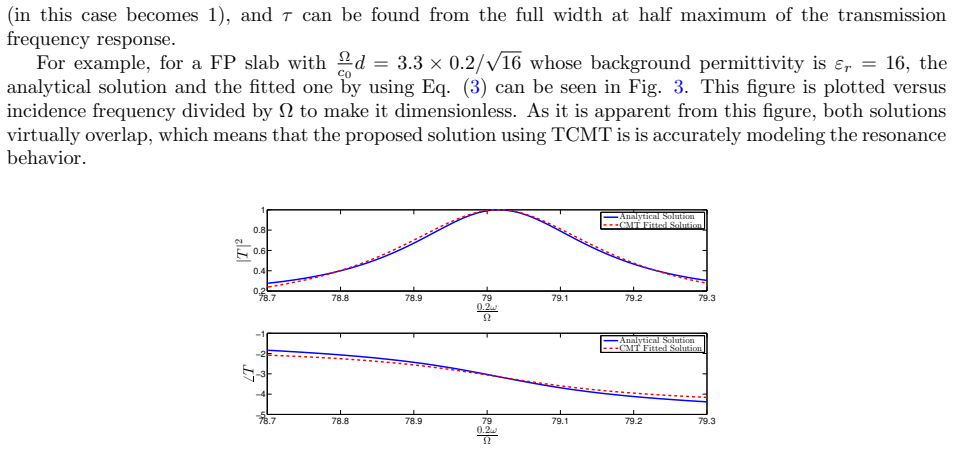
- [Section 2, after Eq. (3)] The sentence 'the proposed solution using TCMT is is accurately modeling the resonance behavior' contains a duplicated 'is'.
- [Equation (15)] The expression for |a⟩(i,1) has e^{+jn(ω+nΩ)t}; the exponent should be j(ω+nΩ)t, with the factor n appearing only in the time-harmonic index, not multiplied inside the exponent.
- [Several figures] The axis labels in Figs. 3, 4, 8, and 10 appear with stray spacing such as '0. 2ω/Ω' and '0. 162ω/Ω'; these should be cleaned to read '0.2 ω/Ω' or similar.
- [Appendix A and numerical results] The number of harmonics N retained in the analytical calculations is not stated anywhere in the main text or figures; please report N for each figure or state that convergence was monitored and specify the criterion.
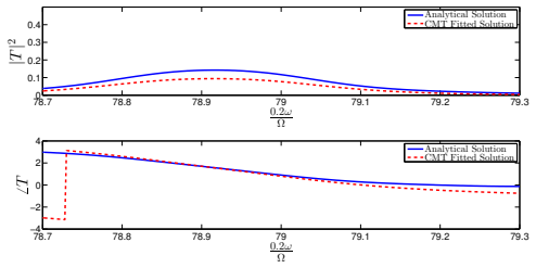
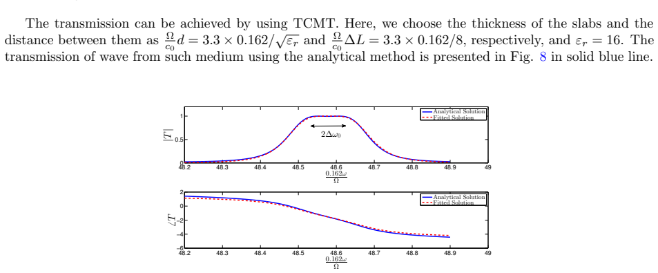
- [Section 3, Fig. 8] The fitted TCMT curve in Fig. 8 is said to have one fitting parameter γ, but the resonance frequencies ω0 and Δω0 are taken from the analytical solution; please state this explicitly so that the reader understands which quantities are fitted and which are extracted.
Circularity Check
The TCMT agreement is a fitted consistency check against the same transfer-matrix solution; the central non-reciprocity claim itself rests on the self-contained GTMM calculation.
-
fitted input called prediction
[Section 2, Eq. (10b), Fig. 5]
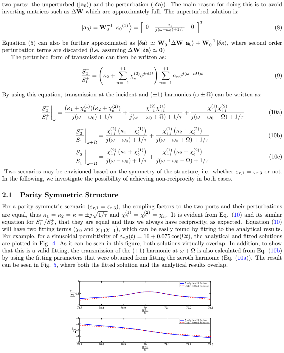
"In addition, to show that this is a valid fitting, the transmission of the (+1) harmonic at ω+Ω is also calculated from Eq. (10b) by using the fitting parameters that were obtained from fitting the zeroth harmonic (Eq. (10a))."
The TCMT parameters are fit to the generalized transfer-matrix solution, called the analytical solution, for the zeroth harmonic; the same analytical solution is then used to verify the +1 harmonic. The agreement in Fig. 5 is therefore a consistency check of the chosen TCMT ansatz, not an independent prediction. Nothing is derived beyond the GTMM output: the fitted coefficients encode the very transfer-matrix response that they later claim to reproduce.
-
fitted input called prediction
[Section 3, after Eq. (18), Table 1 and Figs. 10-13]
"These unknown parameters can be calculated from the transmission response obtained from the analytical method at the frequencies of the denominators of Eq. (18). These values provide six complex numbers, which are sufficient for finding the six unknown complex parameters."
The fitted solution plotted against the analytical solution is obtained by solving for the unknown TCMT coefficients from the analytical transfer-matrix response at selected frequencies. The excellent agreement in Figs. 10-13, and the non-reciprocity explanation built on Table 1, therefore reduce to a parameterization of the very GTMM data they supposedly verify. The central GTMM calculation remains self-contained, but the TCMT does not independently derive the effect.
full rationale
The generalized transfer-matrix method in Appendix A is derived from Maxwell's equations and is not circular; it independently produces the harmonics and the non-reciprocity of Fig. 15. The circularity is confined to the TCMT sections: the paper repeatedly fits TCMT coefficients to the analytical transfer-matrix response and then presents the overlap as excellent agreement. The +1-harmonic check in Fig. 5 uses parameters fitted to the zeroth harmonic of that same analytical solution, so it is a consistency check, not a prediction. Likewise, the two-slab fitted solution in Figs. 10-13 is built from coefficients read off the analytical response, so Table 1's explanation of non-reciprocity is a parameterization of the GTMM data, not an independent derivation. This gives partial circularity. The FDTD run at Δε=4 and ω/Ω=3.86 is a verification gap rather than circularity: it does not cover the headline Δε=0.075, ω/Ω≈193 regime, and so should be evaluated as a correctness or validation concern rather than as a circular step.
Assumptions & free parameters
free parameters (5)
- cavity lifetime τ =
not stated numerically, fitted from static transmission linewidth
- resonance frequency ω0 =
not stated numerically, set to the static transmission maximum
- coupled-mode decay rate γ =
single fitting parameter for two-slab static TCMT, not stated
- TCMT perturbation coefficients α_n and χ_n =
fitted to exact single-slab time-varying transmission
- effective two-slab TCMT coefficients z_n, w_n =
Table 1: w0≈0.01∠−154°, z0≈0.01∠−26°, w1≈0.0012∠140°, z1≈0.0012∠40° for one direction
assumptions (5)
- standard math Floquet-Bloch theorem permits expansion of fields in integer harmonics e^{j(ω+nΩ)t} in a time-periodic medium
- domain assumption Media are linear, lossless, non-magnetic, and the permittivity is periodic in time with frequency Ω in each uniform slab
- ad hoc to paper The time-dependent perturbation only affects the TCMT resonance frequency and coupling coefficients via first-order harmonic terms (n = -1,0,+1)
- ad hoc to paper Higher-order perturbation terms in TCMT can be discarded (ΔW |δa⟩ ≈ 0)
- ad hoc to paper For the two-slab non-reciprocity, the modulation frequency is set equal to the splitting frequency Ω = 2Δω0
Cite this review
Pith. "Pith review of Non-reciprocity using quadrature-phase time-varying slab resonators." pith.science (2026). https://pith.science/paper/QVRYU4ZO
@misc{pith2026190805367,
  author       = {Pith},
  title        = {Pith review of: Non-reciprocity using quadrature-phase time-varying slab resonators},
  year         = {2026},
  howpublished = {\url{https://pith.science/paper/QVRYU4ZO}},
  note         = {Machine review of arXiv:1908.05367}
}
read the original abstract
In this paper, it is shown that non-reciprocity can be observed in time-varying media without employing spatio-temporal modulated permittivities. We show that by using only two one dimensional Fabry-Perot slabs with time-periodic permittivities having quadrature phase difference, it is possible to achieve considerable non-reciprocity in transmission at the incidence frequency. To analyze such scenario,generalized transfer matrices are introduced to find the wave amplitudes of all harmonics in all space. The results are verified by in-house FDTD simulations. Moreover, in order to have a simple model of such time-varying slab resonators, a time-perturbed coupled mode theory is developed for multiple resonances, and it is shown that the results obtained by this method and the analytical method are in excellent agreement.
Figures
Figures from the paper (13 more)





Reference graph
Works this paper leans on
-
[1]
Y. E. Wang, “Time-varying transmission lines (tvtl)-a new pathway to non-reciprocal and intelligent rf front-ends,” in Radio and Wireless Symposium (R WS), 2014 IEEE , pp. 148–150, IEEE, 2014
work page 2014
-
[2]
Non-reciprocity with time-varying transmission lines (tvtls),
Y. E. Wang, “Non-reciprocity with time-varying transmission lines (tvtls),” in Wireless Information Technology and Systems (ICWITS), 2012 IEEE International Conference on , pp. 1–4, IEEE, 2012
work page 2012
-
[3]
S. Taravati, N. Chamanara, and C. Caloz, “Nonreciprocal electromagnetic scattering from a periodically space-time modulated slab and application to a quasisonic isolator,” Physical Review B , vol. 96, no. 16, p. 165144, 2017
work page 2017
-
[4]
Nonrecip- rocal components based on switched transmission lines,
A. Nagulu, T. Dinc, Z. Xiao, M. Tymchenko, D. L. Sounas, A. Al` u, and H. Krishnaswamy, “Nonrecip- rocal components based on switched transmission lines,” IEEE Transactions on Microwave Theory and Techniques, no. 99, pp. 1–20, 2018
work page 2018
-
[5]
Complete optical isolation created by indirect interband photonic transitions,
Z. Yu and S. Fan, “Complete optical isolation created by indirect interband photonic transitions,”Nature photonics, vol. 3, no. 2, p. 91, 2009
work page 2009
-
[6]
Electrically driven nonreciprocity induced by interband photonic transition on a silicon chip,
H. Lira, Z. Yu, S. Fan, and M. Lipson, “Electrically driven nonreciprocity induced by interband photonic transition on a silicon chip,” Physical review letters , vol. 109, no. 3, p. 033901, 2012
work page 2012
-
[7]
Inducing photonic transitions between discrete modes in a silicon optical microcavity,
P. Dong, S. F. Preble, J. T. Robinson, S. Manipatruni, and M. Lipson, “Inducing photonic transitions between discrete modes in a silicon optical microcavity,”Physical review letters, vol. 100, no. 3, p. 033904, 2008
work page 2008
-
[8]
Changing the colour of light in a silicon resonator,
S. F. Preble, Q. Xu, and M. Lipson, “Changing the colour of light in a silicon resonator,” Nature Photonics, vol. 1, no. 5, p. 293, 2007
work page 2007
Show all 21 references
-
[9]
Dynamic release of trapped light from an ultrahigh-q nanocavity via adiabatic frequency tuning,
T. Tanabe, M. Notomi, H. Taniyama, and E. Kuramochi, “Dynamic release of trapped light from an ultrahigh-q nanocavity via adiabatic frequency tuning,” Physical review letters, vol. 102, no. 4, p. 043907, 2009
2009
-
[10]
Simultaneous control of the spatial and temporal spectra of light with space-time varying metasurfaces,
N. Chamanara, Y. Vahabzadeh, and C. Caloz, “Simultaneous control of the spatial and temporal spectra of light with space-time varying metasurfaces,” IEEE Transactions on Antennas and Propagation , 2019
2019
-
[11]
Space-time gradient metasurfaces,
Y. Hadad, D. Sounas, and A. Alu, “Space-time gradient metasurfaces,” Physical Review B , vol. 92, no. 10, p. 100304, 2015
2015
-
[12]
Spacetime processing metasurfaces: Gstc synthesis and prospective applications,
N. Chamanara, Y. Vahabzadeh, K. Achouri, and C. Caloz, “Spacetime processing metasurfaces: Gstc synthesis and prospective applications,” in 2016 IEEE International Symposium on Antennas and Prop- agation (APSURSI) , pp. 365–366, IEEE, 2016. 15
2016
-
[13]
Time-varying metasurfaces and lorentz non-reciprocity,
A. Shaltout, A. Kildishev, and V. Shalaev, “Time-varying metasurfaces and lorentz non-reciprocity,” Optical Materials Express , vol. 5, no. 11, pp. 2459–2467, 2015
2015
-
[14]
Nonreciprocal nongyrotropic magnetless metasurface,
S. Taravati, B. A. Khan, S. Gupta, K. Achouri, and C. Caloz, “Nonreciprocal nongyrotropic magnetless metasurface,” IEEE Transactions on Antennas and Propagation , vol. 65, no. 7, pp. 3589–3597, 2017
2017
-
[15]
New electromagnetic modes in space-time modulated dispersion-engineered media,
N. Chamanara, Z.-L. Deck-L´ eger, C. Caloz, and D. Kalluri, “New electromagnetic modes in space-time modulated dispersion-engineered media,” arXiv preprint arXiv:1710.01625 , 2017
2017 arXiv
-
[16]
Generalized space-time periodic diffraction gratings: Theory and applications,
S. Taravati and G. V. Eleftheriades, “Generalized space-time periodic diffraction gratings: Theory and applications,” arXiv preprint arXiv:1902.09885 , 2019
1902 arXiv
-
[17]
Space-time modulation: Principles and applications,
S. Taravati and A. A. Kishk, “Space-time modulation: Principles and applications,” arXiv preprint arXiv:1903.01272, 2019
1903 arXiv
-
[18]
Determination of guided and leaky modes in lossless and lossy planar multilayer optical waveguides: reflection pole method and wavevector density method,
E. Anemogiannis, E. N. Glytsis, and T. K. Gaylord, “Determination of guided and leaky modes in lossless and lossy planar multilayer optical waveguides: reflection pole method and wavevector density method,” Journal of lightwave technology , vol. 17, no. 5, pp. 929–941, 1999
1999
-
[19]
Temporal coupled-mode theory for the fano resonance in optical resonators,
S. Fan, W. Suh, and J. D. Joannopoulos, “Temporal coupled-mode theory for the fano resonance in optical resonators,” JOSA A , vol. 20, no. 3, pp. 569–572, 2003
2003
-
[20]
Reflection and transmission of a wave incident on a slab with a time-periodic dielectric function ϵ(t),
J. R. Zurita-S´ anchez, P. Halevi, and J. C. Cervantes-Gonzalez, “Reflection and transmission of a wave incident on a slab with a time-periodic dielectric function ϵ(t),” Physical Review A , vol. 79, no. 5, p. 053821, 2009
2009
-
[21]
Temporal coupled-mode theory and the presence of non-orthogonal modes in lossless multimode cavities,
W. Suh, Z. Wang, and S. Fan, “Temporal coupled-mode theory and the presence of non-orthogonal modes in lossless multimode cavities,” IEEE Journal of Quantum Electronics , vol. 40, no. 10, pp. 1511–1518, 2004. 16
2004
Reviewed August 14, 2026 · model on record in the stance chip above.
Discussion (0). Continue with ORCID to comment.