REVIEW 4 major objections 5 minor 9 references
Analysis of Various Transformer Structures for High Frequency Isolation Applications
T0 review · 4 major / 5 minor · reviewed 2026-08-14 · deepseek-v4-flash
Pith's one-line read A family of six transformer structures spans leakage inductance from 5.12 to 736.25 µH and primary-to-secondary parasitic capacitance from 30.6 to 6444 pF, so winding and core layout can be chosen to balance the two parasitics.
desk verdict Useful comparative FEM dataset for transformer parasitics, but the capacitance extraction likely mixes core-to-ground effects into the primary-secondary values and needs validation. read the letter →
The pith
A machine-rendered reading of the paper's core claim, the machinery that carries it, and where it could break.
The reading
What carries the argument
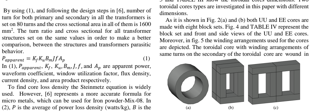
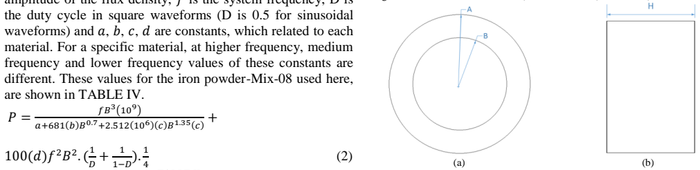
The carrying mechanism is the finite-element energy method for parasitic extraction. Leakage inductance is obtained from the magnetic energy stored in the whole space with the secondary short-circuited, and parasitic capacitance from the electric energy stored with 1 V applied across the windings, so the computed quantities are direct integrals of field solutions rather than closed-form estimates. The simulations use 3D models of toroidal, UU, and EE cores with an Iron Powder-Mix-08 B-H curve, AWG 8 windings, 0.15 mm inter-conductor insulation, and a 2 mm bobbin, with magnetizing inductance held nearly equal across designs so that the parasitic comparison is clean.
What would settle it
Build one of the simulated transformers, say the EE core with P-S-P-S-P-S-P-S interleaving predicted at 5.12 µH leakage and 6704 pF capacitance, measure its open- and short-circuit impedance over 10 kHz to 1 MHz with an impedance analyzer, and check whether the extracted values match the simulation; a large mismatch, or a mesh-refinement study that shifts the FEM results substantially, would overturn the claim.
Extended reading notes
Core claim
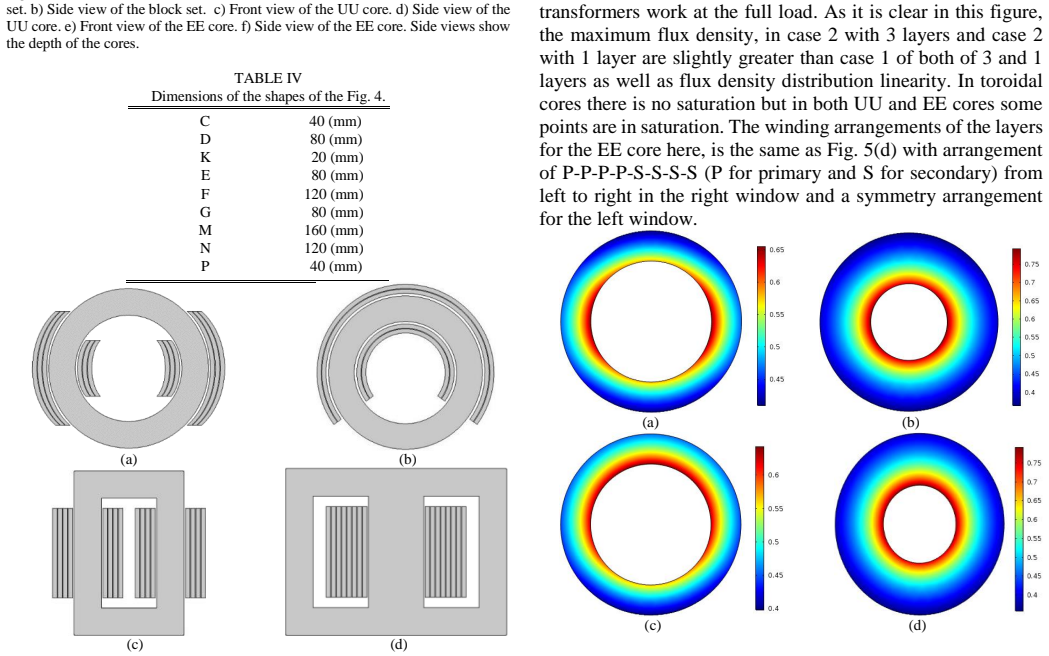
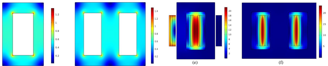
For a 1:1, 400 V, 8 kVA transformer at 10 kHz with 80 turns, 1600 mm² core area, and iron-powder cores, the FEM calculations show that leakage inductance is set mainly by window-area volume and winding layout: the two toroidal non-overlaid cases store the most leakage energy (736.25 and 324.89 µH), while the overlaid toroids and interleaved EE cores store the least (15.21, 9.23, and 5.12 µH). Parasitic capacitance behaves oppositely: overlaid toroids and interleaved EE windings develop the largest primary-secondary capacitances (6444 pF and up to 6704 pF), while non-overlaid toroids and the UU core stay below 76 pF with the iron-powder core. The paper's central claim is that this wide, quantifiable spread is a usable design handle: each structure occupies a different point on a leakage-versus-capacitance map, and interleaving is a deliberate lever that trades inductance down while capacitance goes up.
Load-bearing premise
The computed parasitic values are taken from FEM simulations that assume the Iron Powder-Mix-08 B-H curve, homogeneous winding layers with 0.15 mm insulation, a 2 mm bobbin, and unit relative permeability for non-core materials, without experimental validation or a mesh-convergence check.
Editorial extensions
If this is right
- A designer can intentionally choose a transformer structure whose leakage inductance serves as the resonant tank inductance, removing a separate inductor; the paper cites a prior result where this shrank system volume by 15 percent.
- For fast-switching SiC and GaN converters, low-leakage interleaved EE windings come with high parasitic capacitance, so the injected high-frequency current and resulting EMI must be checked before adoption.
- Because magnetizing inductance is held nearly constant across structures, the wide spread in parasitic values is attributable to geometry and winding layout rather than to different core flux levels.
- Near-identical leakage values can accompany very different capacitances: interleaved EE types a and b give 5.12 versus 19.90 µH and 6704 versus 2875 pF, so selecting a structure should use both parameters together.
- Magnetic saturation also enters the selection: the toroidal cores show no saturation at full load while the UU and EE cores have some saturated points, adding a constraint beyond parasitics.
Reading between the lines
- One consequence the paper leaves implicit is that the six structures trace a leakage-versus-capacitance frontier: the lowest-capacitance designs (non-overlaid toroids, 30–76 pF) sit at the highest leakage (325–736 µH), and the lowest-leakage designs (interleaved EE, below 20 µH) sit above 2.9 nF. A designer could plot these points and pick the nearest structure to a required (L,C) target.
- The strong dependence of capacitance on core conductivity—76.3 pF versus 1.87 pF for one toroid when iron powder is replaced by ferrite-NiZn—suggests core material choice is as powerful a lever as winding geometry. Combining a non-conductive core with interleaving to reach low leakage and low capacitance simultaneously is a natural next simulation.
- Since all results are for one operating point (10 kHz, 1:1, 8 kVA), a testable extension is to sweep frequency and power and see whether the ordering of structures by parasitic severity holds, especially as skin effect changes leakage at higher frequencies.
Signed reviews
Editorial analysis
A structured set of objections, weighed in public.
Referee Report
Summary. The manuscript uses 3D finite-element simulations to compute magnetizing inductance, leakage inductance, AC resistance, and primary-to-secondary parasitic capacitance for six high-frequency transformer configurations (two toroidal, one UU, one EE, plus two toroidal core-size variants) designed for 400 V/400 V, 8 kVA, 10 kHz operation. It also studies three interleaved winding arrangements for the EE core. The central claim is that the investigated structures span a wide range of leakage inductance (5.12 to 736.25 µH) and parasitic capacitance (1.346 to 6444.137 pF) so that designers can choose a structure that balances the two parasitics for a given application.
Significance. If the extracted parasitic values are correct, the paper provides a useful design-oriented comparison of core geometries and winding arrangements, and the interleaving study quantifies an important trade-off. The use of FEM energy-based extraction is standard, and the systematic comparison across six structures, including two core materials, is a strength. However, the capacitance extraction appears to include core-to-winding contributions when a conductive iron-powder core is present, and the absolute values are not validated by measurements, mesh-convergence studies, or analytic checks. The claimed quantitative design map therefore needs correction and additional support before the central conclusion can be accepted.
major comments (4)
- [Section IV-B, Eqs. (7)-(9), Fig. 9, Table VI] The reported 'capacitance between primary and secondary windings' is extracted from total electrostatic stored energy with the secondary held at 0 V. In the companion insulation test of Fig. 8 the cores are explicitly grounded, and the text does not state the core boundary condition for the capacitance extraction. If the conductive iron-powder core is also grounded (or otherwise at a fixed potential), the stored energy includes the primary-to-core capacitance in parallel with the primary-to-secondary capacitance. The low iron-powder entries for types a, b, and e (76.258, 30.603, and 60.577 pF) would then not be comparable with the ferrite entries (1.869, 1.346, and 7.312 pF) as winding-to-winding values, and the abstract's trade-off claim is based on a potentially inflated quantity. Please state the core potential used in the capacitance simulation; if the core is grounded, rerun with the core excluded or with partial capacitances separated, and revise the design-space conclusions accordingly.
- [Section IV-A, Table V] The leakage inductance of case a is 736.25 µH against a magnetizing inductance of 2061.5 µH, implying a coupling coefficient of only about 0.74 for a toroidal transformer. This is a surprising result that likely depends on the assumed homogeneous multi-layer winding model and on mesh resolution. No mesh-convergence study, solver settings, or analytic estimate is reported. Without these, the quantitative range of leakage values in Table V, and the design conclusions drawn from it, are not established.
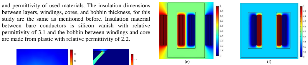
- [Section II and Section IV] The simulations rely on several unvalidated modeling assumptions: the B-H curve of Iron Powder-Mix-08 (Fig. 1), homogeneous winding layers with fixed 0.15 mm insulation, 2 mm bobbin thickness, and relative permeability of 1 for all non-core materials. Since the paper's central claim is a quantitative trade-off map, at least one experimental measurement or a comparison with a published benchmark transformer is needed to confirm that the FEM model reproduces parasitic values with acceptable accuracy. As written, the absolute values are not verifiable.
- [Section IV-C, Table VII] The interleaved-winding capacitance values (6704.1, 2875.0, and 3832.3 pF) are extracted with the same method as Table VI, so they inherit the same core-ground issue. In addition, the conclusion that leakage inductance is reduced while capacitance increases is qualitatively expected, but the quantitative values and the comparison between types a and b should be revisited once the capacitance extraction is corrected.
minor comments (5)
- [Throughout] There are multiple typos and grammatical errors that should be corrected, including 'capacitacne' (Table VI), 'transforemrs' and 'distribuiton' (Fig. 9 caption), and 'silicon vanish' (Section IV-B).
- [Equation (2)] Equation (2) is not typeset correctly: the denominator contains an extra '(c)' and mismatched parentheses, so the core-loss formula is not usable as printed. Please rewrite it with clear notation and define all constants consistently with Table II.
- [Section IV-B] The text says the maximum electric field of 67 kV/mm in Fig. 8(a) is 'much lower' than the dielectric strength of silicon varnish (120 kV/mm); while it is lower, the margin is not large, and the wording should be adjusted to reflect the actual ratio.
- [References] The citation to 'IEEE Std. C57.12.01' is incomplete; the full standard number, year, and title should be provided, and reference [8] should be cited with page numbers or a DOI where available.
- [Section III] The terms 'case 1' and 'case 2' for the toroidal cores are used in the text and figures but are not explicitly defined in Table III; please add labels so that the reader can map the cases to the dimensions.
Circularity Check
No circularity; FEM-based field-energy extraction is self-contained and does not reduce to fitted inputs or self-citation.
full rationale
The paper computes leakage inductance and parasitic capacitance directly from finite-element field solutions using standard energy relations: leakage inductance from stored magnetic energy with the secondary short-circuited (Eqs. 3-6, Table V), and capacitance from stored electrostatic energy with 1 V applied to one winding and the other at 0 V (Eqs. 7-9, Table VI). No parameter is fitted to the reported parasitic values, and no target quantity is used as an input to the calculation that then 'predicts' that same quantity. The design choices (80 turns, 1600 mm2 core area, fixed insulation and bobbin dimensions) are stated up front and are independent of the extracted parasitics. The cited 'procedure used in [9]' is an external FEM-based capacitance extraction method, not a self-citation, and it is not used to justify the paper's comparative conclusions. The only author-overlapping reference, [5], concerns robust backstepping control of synchronverters and is not load-bearing for the transformer analysis. Even the possible correctness concern that the iron-powder core capacitance may be included in the reported primary-secondary capacitance is a modeling and interpretation issue, not a circularity issue: the reported numbers are genuine outputs of the stated FEM setup, not inputs disguised as predictions. The paper's central claim, that different structures and winding arrangements give a wide range of leakage inductance and parasitic capacitance, follows directly from the independent field simulations and tables. Therefore the derivation chain is self-contained, and no circular step is present.
Assumptions & free parameters
assumptions (4)
- domain assumption Stored field energy from FEM can be converted to lumped leakage inductance and capacitance using E = 0.5 L I^2 and E = 0.5 C V^2 (Eqs. 6 and 9).
- domain assumption Material properties (silicon varnish permittivity 3.1, plastic bobbin permittivity 2.2, dielectric strengths 120, 25, and 3 kV/mm) are accurate.
- domain assumption The Iron Powder-Mix-08 B-H curve and Steinmetz coefficients (Table II) represent the core material behavior.
- domain assumption The FEM geometry with all non-core materials at relative permeability 1 and homogeneous winding layers captures the relevant parasitic behavior.
Cite this review
Pith. "Pith review of Analysis of Various Transformer Structures for High Frequency Isolation Applications." pith.science (2026). https://pith.science/paper/SHRXWWVK
@misc{pith2026190805388,
  author       = {Pith},
  title        = {Pith review of: Analysis of Various Transformer Structures for High Frequency Isolation Applications},
  year         = {2026},
  howpublished = {\url{https://pith.science/paper/SHRXWWVK}},
  note         = {Machine review of arXiv:1908.05388}
}
read the original abstract
High frequency transformers are an integral part of power electronics devices and their parasitic parameters influence the performance and efficiency of the overall system. In this paper, transformer leakage inductances and parasitic capacitances are analyzed using finite element method (FEM) for different structures and windings arrangements of high frequency transformers. Also, magnetic field, electric field, and voltage distribution within the transformer is simulated and analyzed. Six different high frequency transformers with toroidal, EE, and UU cores with different windings are investigated for a 400(V)/400(V), 8 kVA transformer operating at 10 kHz. Additionally, interleaved windings for EE core are simulated and results compared with previous outcomes. Analysis results will help categorize each structure, based on its balance between leakage inductances and series parasitic capacitance. This information can later be used for optimal selection of transformers as a function of their operating frequency and enable designers to compromise between various parameters in different applications, especially new fast switches such as SiC and GaN.
Figures

Figures from the paper (6 more)



Reference graph
Works this paper leans on
-
[1]
Ac-ac dual active bridge converter for solid state transformer,
H. Qin and J. Kimball, “Ac-ac dual active bridge converter for solid state transformer,” 2009 IEEE Energy Conversion Congress and Exposition, 2009
work page 2009
-
[2]
B. Zhao, Q. Song, W. Liu, and Y. Sun, “Overview of Dual-Active-Bridge Isolated Bidirectional DC –DC Converter for High -Frequency-Link Power - Conversion System,” IEEE Transactions on Power Electronics, vol. 29, no. 8, pp. 4091–4106, 2014
work page 2014
-
[3]
Calculation of Leakage Inductance for High-Frequency Transformers,
Z. Ouyang, J. Zhang, and W. G. Hurley, “Calculation of Leakage Inductance for High-Frequency Transformers,” IEEE Transactions on Power Electronics, vol. 30, no. 10, pp. 5769–5775, 2015
work page 2015
-
[4]
Design of Leakage Inductance in Resonant DC -DC Converter for Electric Vehicle Charger,
J.-M. Choi, B.-J. Byen, Y.-J. Lee, D.-H. Han, H.-S. Kho, and G.-H. Choe, “Design of Leakage Inductance in Resonant DC -DC Converter for Electric Vehicle Charger,” IEEE Transactions on Magnetics, vol. 48, no. 11, pp. 4417– 4420, 2012
work page 2012
-
[5]
Robust Backstepping Control of Synchronverters under Unbalanced Grid Condition,
S. Yazdani and M. Ferdow si, “Robust Backstepping Control of Synchronverters under Unbalanced Grid Condition,” 2019 IEEE Power and Energy Conference at Illinois (PECI), 2019
work page 2019
-
[6]
C. W. T. McLyman, Transformer and inductor design handbook . CRC Press, 2017
work page 2017
-
[7]
M. K. Kazimiercz uk, High-frequency magnetic components . Chichester: John Wiley & Sons, 2014
work page 2014
-
[8]
High-Frequency Transformer Design for Modular Power Conversion From Medium-Voltage AC to 400 VDC,
S. Zhao, Q. Li, F. C. Lee, and B. Li, “High-Frequency Transformer Design for Modular Power Conversion From Medium-Voltage AC to 400 VDC,” IEEE Transactions on Power Electronics, vol. 33, no. 9, pp. 7545–7557, 2018
work page 2018
Show all 9 references
-
[9]
A finite -element analysis approach to determine the parasitic capacitances of high -frequency multiwinding transformers for photovoltaic inverters,
M. B. Shadmand and R. S. Balog, “A finite -element analysis approach to determine the parasitic capacitances of high -frequency multiwinding transformers for photovoltaic inverters,” 2013 IEEE Power and Energy Conference at Illinois (PECI), 2013
2013
Reviewed August 14, 2026 · model on record in the stance chip above.
Discussion (0). Continue with ORCID to comment.