REVIEW 4 major objections 6 minor 29 references
Controlling branching angle of waveguide splitters based on GRIN lenses
T0 review · 4 major / 6 minor · reviewed 2026-08-14 · deepseek-v4-flash
Pith's one-line read Generalized Maxwell fisheye and Eaton gradient-index lenses can set a waveguide splitter's branching angle—25°, 45°, 65°, and 90°—turning wide-angle splitting into a matter of lens profile rather than junction geometry.
desk verdict A plausible GRIN-lens splitter design with real simulation support, undercut by an unstated regularization of the divergent index and a truncation claim their own numbers contradict. read the letter →
The pith
A machine-rendered reading of the paper's core claim, the machinery that carries it, and where it could break.
The reading
What carries the argument
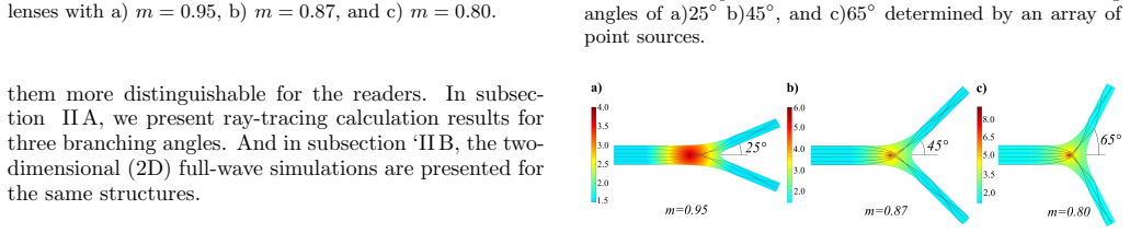
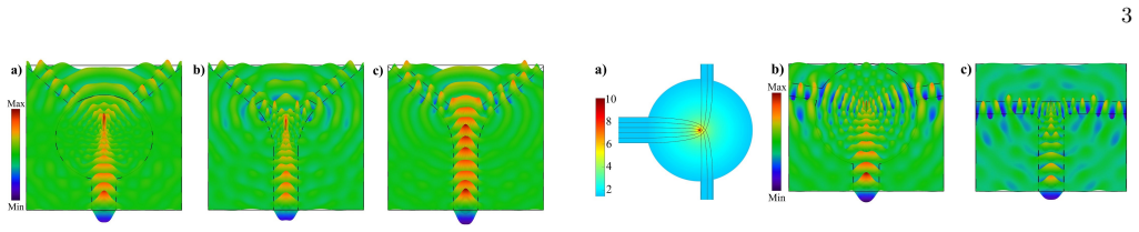
The central objects are two radial refractive-index profiles. The GMFE profile is $n_{\mathrm{lens}}(r) = 2 n_{\mathrm{edge}}/((r/R)^{1-m} + (r/R)^{1+m})$ for $0.5 \le m \le 1$, which interpolates between Maxwell's fisheye at $m=1$ and a source-refocusing lens at $m=0.5$; intermediate $m$ sends rays from an edge point to two focal points whose angular separation grows as $m$ falls. The Eaton profile for a 90° bend obeys $n_{\mathrm{lens}}^2 = R/(n_{\mathrm{lens}} r) + \sqrt{(R/(n_{\mathrm{lens}} r))^2 - 1}$, ranging from unity at the edge to infinity at the center, and an on-center incident beam splits into a T-junction. The argument is carried by ray tracing with an array of point sources across the input waveguide width, which fixes the output angle correctly where a single point source would not, and by 2D full-wave finite-element simulations at 1550 nm with the lens edge index matched to the waveguide core.
What would settle it
Build or simulate the truncated Eaton 90° splitter with the lens-center index capped at the maximum value a real isotropic metamaterial can reach at 1550 nm (for instance $n\approx 3$), and check whether the output still exits at 90° with efficiency near the reported 41%.
Extended reading notes
Core claim
The central claim is that GRIN lenses with two focal points control the branching angle of a waveguide power splitter: lowering the GMFE parameter $m$ (0.95, 0.87, 0.80) yields output angles of 25°, 45°, and 65°, and an on-center beam through an Eaton lens yields a 90° T-junction split. Full-wave simulations give splitting efficiencies of 32–35% for the GMFE splitters (35% for the complete 65° lens, 33% for the truncated 25° lens) and 41% for the truncated Eaton 90° splitter. The same simulations give 35%, 8%, and 0.2% for the corresponding lensless Y-junctions at 25°, 45°, and 65°, so the lenses matter most at wide angles. The price of this flexibility is a central refractive index that tends to infinity, which the authors state requires isotropic metamaterials rather than the anisotropic metamaterials used by transformation-optics splitters.
Load-bearing premise
The design assumes that refractive-index profiles rising toward infinity at the lens center can be realized as low-loss isotropic metamaterials matched to a SiN waveguide, and that a two-dimensional effective-index slab ($n_{\mathrm{core}}=1.57$, TE mode) represents the three-dimensional device.
Editorial extensions
If this is right
- Wide-angle splitting at 45° to 90° becomes achievable in moderate-index-contrast waveguides by embedding a truncated GRIN lens, with simulated splitting efficiencies of 22% to 41%.
- The output angle of a GMFE splitter is set by the exponent $m$ rather than by the taper geometry, so sweeping $m$ gives a one-parameter family of splitters.
- A lensless Y-junction degrades sharply as the angle grows (8% at 45°, 0.2% at 65° in these simulations), whereas the lens designs keep efficiency around 22–35%, so the lens approach matters most exactly where conventional splitters fail.
- Truncating the lens to reduce footprint causes only a modest efficiency drop (for example, 35% to 29% for the 65° GMFE splitter), making the device practical for compact integration.
Reading between the lines
- Sweeping $m$ between 0.5 and 1 should produce a continuous range of splitting angles, not just the three discrete values shown; a calibration curve of output angle versus $m$ would be a direct testable extension.
- Since the center index diverges, any fabricated device will have a capped index; simulating the same profiles with the center index clamped to realistic metamaterial values (say $n\approx 3$ to $5$) would reveal whether the angle and efficiency survive the cap.
- The same Eaton lens acting as a 90° bend for off-center input and a 90° splitter for on-center input suggests a single structure could be switched between routing and splitting functions.
- A 3D full-wave simulation with vertical confinement would test whether the 2D effective-index results, especially the 41% Eaton efficiency, persist in the actual SiN-on-SiO2 geometry.
Signed reviews
Editorial analysis
A structured set of objections, weighed in public.
Referee Report
Summary. This manuscript proposes wide-angle waveguide power splitters based on gradient-index (GRIN) lenses with two focal points: the generalized Maxwell fisheye (GMFE) lens and the Eaton lens. The index profiles are given in Eqs. (2) and (3), with the edge index matched to the waveguide effective index (nedge = ncore = 1.57) for a 250 nm SiN guiding layer represented in a 2D effective-index model. Ray tracing with an array of point sources in a 2 µm wide input waveguide is used to obtain branching angles of 25° (m = 0.95), 45° (m = 0.87), and 65° (m = 0.80) for the GMFE lens, and a 90° T-junction behavior for the Eaton lens. Two-dimensional FEM at 1550 nm then reports per-branch splitting efficiencies for complete and truncated lens designs: 32%/33% (25°), 29%/22% (45°), 35%/29% (65°), and 30% at 80° (complete Eaton lens) versus 41% at 90° (truncated Eaton lens), with a no-lens Y-junction baseline of 35%, 8%, and 0.2% for the three GMFE angles. The authors conclude that the designs cannot be implemented by conventional graded-index fabrication and require isotropic metamaterials because the central index diverges.
Significance. If the reported results are valid, the paper offers a conceptually simple alternative to transformation-optics splitters: a one-parameter lens profile (m) that tunes the splitting angle over a wide range using isotropic media only. The study is strengthened by the use of two complementary simulation methods (ray tracing and FEM) on identical structures, by the explicit no-lens baseline that quantifies when the lens is actually beneficial (at 45° and 65°), and by the authors' candid acknowledgment in the abstract and Section IV that the extreme central index exceeds the reach of conventional graded-index fabrication. The designs are falsifiable in the sense that each m value yields a concrete ray-traced angle and a concrete FEM efficiency. The principal weaknesses are that the singular index profiles are never regularized in the simulations, the truncation claim is internally contradicted by the paper's own numbers, and the full-wave analysis never verifies the branching angle itself, which is the quantity in the title.
major comments (4)
- [§II.B and Eqs. (2)–(3)] The treatment of the index singularity at the lens center is never specified. Both n_lens(r) profiles diverge at r = 0, so neither the ray tracer nor the FEM solve can use them as written; some regularization (an index cap, a central cutout, or another procedure) must have been applied, and its parameters (maximum index, cutoff radius, mesh resolution) are not reported. No mesh-convergence or error analysis is given for the reported efficiencies. Because every quantitative claim (32/33/29/22/35/29/30/41%) is computed under this unspecified regularization, and because any physical metamaterial has a finite maximum index, the results are not reproducible as reported and the implied insensitivity to the center behavior is unverified.
- [§II.A vs. §II.B] The statement in §II.A that the lens 'can be truncated without any degradation of its performance' is contradicted by the full-wave numbers in §II.B: for m = 0.87 the complete lens gives 29% versus 22% for the truncated lens, and for m = 0.80 the values are 35% versus 29%. Only the m = 0.95 case (32% versus 33%) is consistent with the claim. Because the truncated Eaton lens is the version recommended for the 90° splitter in §III, this internal inconsistency bears on the main design recommendation and must be resolved, either by qualifying the truncation claim or by explaining the origin of the degradation.
- [§III, Eaton lens] The 90° splitter claim rests on the truncated lens (41% efficiency), whereas the complete lens is reported to reach at most 30%, and at 80° rather than 90°. The sentence 'the maximum splitting efficiency of 30% is achieved when the branching angle is 80°' implies a parameter sweep that is never described, and the fact that truncation improves the Eaton lens while degrading the GMFE lenses in §II.B is left unexplained. As presented, the complete-lens and truncated-lens results are not directly comparable, and the headline 90° result is not backed by a full-wave simulation of the complete lens.
- [§II.B and §III] The quantity named in the title, the branching angle, is never verified in the full-wave simulations. The FEM analysis reports only the per-branch efficiency; the field maps of Figs. 4–7 are not used to measure the direction of the transmitted beams, to compare the field angles with the ray-traced 25°/45°/65°/90° values, or to estimate how much power radiates outside the designed output arms. Without this verification, the FEM results confirm that some power reaches the output waveguides but do not independently validate the angle-control claim, and the angle remains effectively a ray-tracing design choice rather than a predicted observable.
minor comments (6)
- [Fig. 3 caption] The caption lists the branching angles as 'a) 625° b) 45°, and c) 65°'; '625°' should read '25°'.
- [§II.A] There are minor typographical issues: '250nm-thickSiN' lacks spaces, and the phrase 'In subsection ‘II B' has a missing closing quote and space.
- [§II.A] The 2D model places the ncore = 1.57 waveguide directly against air cladding (n = 1), whereas the physical stack has SiO2 cladding (n ≈ 1.45) on one side and air on the other; the authors should justify this effective-index idealization or comment on its effect on leakage and on reflection at the lens–waveguide interface.
- [§II.B] Because P_split is the power in each branching arm, a lossless equal 1×2 splitter would give 50% per branch; quoting the efficiency relative to this bound, or reporting the total power collected in the two output arms, would let the reader judge whether 29–35% is a competitive result.
- [§III] Please clarify the meaning of 'the maximum splitting efficiency of 30% is achieved when the branching angle is 80°': if the angle was scanned, describe the sweep; otherwise rephrase to avoid implying an unexplained optimization.
- [§II] The paper demonstrates three (m, angle) working points but provides no design rule (for example, a curve of ray-traced angle versus m, or a prescription for positioning the output waveguides); such a mapping would substantiate the claimed ability to control the branching angle rather than merely to exhibit chosen cases.
Circularity Check
No significant circularity: branching angles are design targets tuned via m, and full-wave FEM independently solves Maxwell's equations.
full rationale
The paper's derivation chain is simulation-based rather than analytic. The GMFE index profile of Eq. (2) and the Eaton profile of Eq. (3) are taken from the external literature (Tyc et al. and the standard Eaton lens), not from the authors' prior fitted work. The branching angles 25, 45, 65, and 90 degrees are design targets: the parameter m is adjusted until ray tracing shows the desired separation, and the same ray-tracing is then used to report the angle. This is an inverse-design procedure, not a first-principles prediction, so there is no formal 'fitted input called prediction': the paper does not claim to derive the angle from the profile alone. The full-wave FEM simulations provide an independent numerical solution of Maxwell's equations and are used to evaluate splitting efficiency, not to re-fit the angles. The only mild concerns are that the claimed angles are not independently validated by the full-wave fields and that the singular index at the lens center is not regularized in the FEM description, but these are correctness risks, not circularity. The self-citations (Refs. 15, 16, 19, 20, 26-29) are background implementation references and are not load-bearing; the lens profiles themselves are external standard results. Therefore no circular step meets the quoted-reduction standard required by this review.
Assumptions & free parameters
free parameters (4)
- GMFE exponent m =
0.95, 0.87, 0.80
- Lens radius R_lens =
4 micrometers
- Waveguide widths =
input 2 micrometers, branches 1 micrometer
- Edge refractive index nedge =
1.57
assumptions (5)
- standard math GMFE profile Eq. (2) and Eaton profile Eq. (3), taken from Refs. [22] and [19,20,24], correctly describe ray paths and focusing.
- domain assumption The 2D effective-index model with ncore=1.57 represents the TE mode of the 250 nm SiN slab waveguide with SiO2 substrate and air cladding.
- domain assumption Geometrical optics ray tracing with an array of point sources reproduces the wave behavior of a finite-width input waveguide.
- domain assumption Isotropic metamaterials can implement the high or diverging refractive index at the lens center with acceptable loss.
- domain assumption Matching nedge to ncore suppresses interface reflections.
Cite this review
Pith. "Pith review of Controlling branching angle of waveguide splitters based on GRIN lenses." pith.science (2026). https://pith.science/paper/RH63BIDZ
@misc{pith2026190805623,
  author       = {Pith},
  title        = {Pith review of: Controlling branching angle of waveguide splitters based on GRIN lenses},
  year         = {2026},
  howpublished = {\url{https://pith.science/paper/RH63BIDZ}},
  note         = {Machine review of arXiv:1908.05623}
}
abstract
Designing beam splitting structures with wide branching angles is of great significance. The branching angle of conventional Y-junctions is limited. In this paper, we investigate the possibility of utilizing gradient index (GRIN) lenses with two focal points such as the generalized Maxwell's fisheye (GMFE) and Eaton lenses in controlling the branching angle of power splitters. The GMFE lens can provide a wide range of branching angles, however, we present only splitting angles of 25$^\circ$, 45$^\circ$, and 65$^\circ$. Furthermore, we propose a 90$^\circ$ splitter structure by employing the Eaton lens. We evaluate the performance of the proposed power splitters by ray-tracing and full-wave finite element method. While GRIN lenses provide a broad range of splitting angles, they require isotropic metamaterials to implement high refractive indices at the center of these lenses.
Figures


Figures from the paper (2 more)

Reference graph
Works this paper leans on
-
[1]
Q. Wang, J. Lu, and S. He, Applied optics 41, 7644 (2002)
work page 2002
-
[2]
H. Hatami-Hanza, P. Chu, and M. Lederer, IEEE pho- tonics technology letters
-
[3]
X. Li, H. Xu, X. Xiao, Z. Li, J. Yu, and Y. Yu, Optics letters 38, 4220 (2013)
work page 2013
-
[4]
S. Safavi-Naeini, Y. Chow, S. Chaudhuri, and A. Goss, Journal of lightwave technology 11, 567 (1993)
work page 1993
- [5]
-
[6]
P. Wang, G. Brambilla, Y. Semenova, Q. Wu, and G. Farrell, (2011)
work page 2011
-
[7]
H. Chen, L. Ran, J. Huangfu, X. Zhang, K. Chen, T. M. Grzegorczyk, and J. A. Kong, Journal of applied physics 94, 3712 (2003)
work page 2003
-
[8]
C. Caloz, C.-C. Chang, and T. Itoh, Journal of Applied Physics 90, 5483 (2001)
work page 2001
Show all 29 references
-
[9]
Leonhardt and T
U. Leonhardt and T. G. Philbin, in Progress in Optics , Vol. 53 (Elsevier, 2009) pp. 69–152
2009
-
[10]
M. Rahm, D. Roberts, J. Pendry, and D. Smith, Optics Express 16, 11555 (2008)
2008
-
[11]
M. Rahm, S. A. Cummer, D. Schurig, J. B. Pendry, and D. R. Smith, Physical Review Letters 100, 063903 (2008)
2008
-
[12]
Y.-L. Wu, Z. Zhuang, L. Deng, and Y.-A. Liu, Scientific reports 6, 24495 (2016)
2016
-
[13]
Viaene, V
S. Viaene, V. Ginis, J. Danckaert, and P. Tassin, Physi- cal Review B 95, 155412 (2017)
2017
-
[14]
Viaene, V
S. Viaene, V. Ginis, J. Danckaert, and P. Tassin, Physi- cal Review B 93, 085429 (2016)
2016
-
[15]
Gilarlue and S
M. Gilarlue and S. H. Badri, Optics Communications 450, 308 (2019)
2019
-
[16]
S. H. Badri, H. R. Saghai, and H. Soofi, Applied Optics 58, 4647 (2019)
2019
-
[17]
Sayanskiy, S
A. Sayanskiy, S. Glybovski, V. P. Akimov, D. Filonov, P. Belov, and I. Meshkovskiy, IEEE Antennas and Wire- less Propagation Letters 16, 1520 (2017)
2017
-
[18]
Quevedo-Teruel, J
O. Quevedo-Teruel, J. Miao, M. Mattsson, A. Algaba- Brazalez, M. Johansson, and L. Manholm, IEEE Anten- nas and Wireless Propagation Letters 17, 1588 (2018)
2018
-
[19]
S. H. Badri and M. Gilarlue, JOSA B 36, 1288 (2019)
2019
-
[20]
S. H. Badri, H. R. Saghai, and H. Soofi, Applied Optics 58, 5219 (2019)
2019
-
[21]
Q. Lei, R. Foster, P. S. Grant, and C. Grovenor, IEEE Transactions on Microwave Theory and Techniques 65, 4823 (2017)
2017
-
[22]
T. Tyc, L. Herz´ anov´ a, M.ˇSarbort, and K. Bering, New Journal of Physics 13, 115004 (2011)
2011
-
[23]
Eskandari, M
H. Eskandari, M. S. Majedi, A. R. Attari, and O. Quevedo-Teruel, New Journal of Physics 21, 063010 (2019)
2019
-
[24]
G. Du, M. Liang, R. A. Sabory-Garcia, C. Liu, and H. Xin, IEEE Antennas and Wireless Propagation Let- ters 15, 1487 (2016)
2016
-
[25]
M. Yin, X. Yong Tian, L. Ling Wu, and D. Chen Li, Applied Physics Letters 104, 094101 (2014)
2014
-
[26]
Gilarlue, S
M. Gilarlue, S. H. Badri, H. R. Saghai, J. Nourinia, and C. Ghobadi, Photonics and Nanostructures- Fundamentals and Applications 31, 154 (2018)
2018
-
[27]
S. H. Badri and M. Gilarlue, Optik 185, 566 (2019)
2019
-
[28]
Gilarlue, J
M. Gilarlue, J. Nourinia, C. Ghobadi, S. H. Badri, and H. R. Saghai, Optics Communications 435, 385 (2019)
2019
-
[29]
S. H. Badri, H. R. Saghai, and H. Soofi, Journal of Optics 21, 065102 (2019)
2019
Reviewed August 14, 2026 · model on record in the stance chip above.
Discussion (0). Continue with ORCID to comment.