REVIEW 3 major objections 5 minor 1 cited by
Investigation of the Power Consumption of the PETsys TOFPET2 ASIC
T0 review · 3 major / 5 minor · reviewed 2026-08-14 · deepseek-v4-flash
Pith's one-line read The TOFPET2 ASIC's power draw can be predicted from three software settings, ranging from 3.6 to 7.2 mW per channel.
desk verdict Careful ASIC power measurements with a model section that doesn't reproduce as printed—fixable, but equations and Table II need reconciliation. read the letter →
The pith
A machine-rendered reading of the paper's core claim, the machinery that carries it, and where it could break.
The reading
What carries the argument
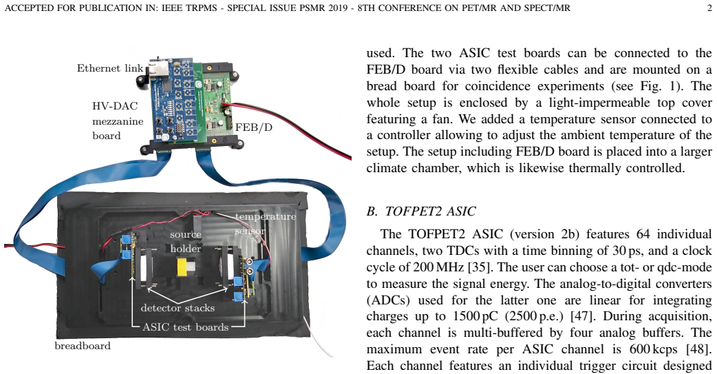
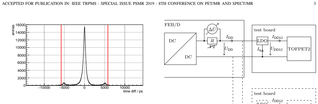
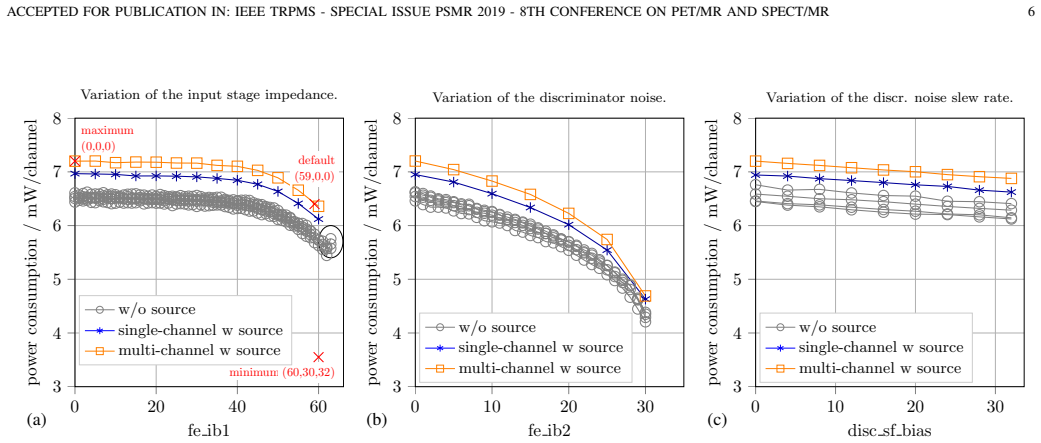
The load-bearing machinery is the linear superposition model of Eq. (4), which splits per-channel power into a baseline $P_0$ and three deltas: $dP_{feib1}$, $dP_{feib2}$, and $dP_{discsfbias}$. The parameters are software settings: fe_ib1 adjusts the input-stage impedance from 11 to 32 ohm, fe_ib2 adjusts a preamplifier current that sets discriminator noise and signal amplification, and disc_sf_bias adjusts the biasing of discriminator signal buffers; increasing any of the three lowers the power draw. Each delta is a least-squares fit of a piecewise linear or parabolic curve to single-parameter scans in which the other two parameters are held at zero. The experimental basis is a shunt-resistor measurement on the 1.2-V low-dropout regulator line, which isolates ASIC operating power from FPGA communication power. The model's defining move is to assert that those single-axis curves continue to hold throughout the three-dimensional parameter space, so a designer can compute the power of an arbitrary configuration triple before running the system.
What would settle it
A targeted grid of two-parameter combinations, e.g., holding fe_ib2=15 and disc_sf_bias=16 while varying fe_ib1, would settle the independence assumption: if measured $P_{ch} - P_0$ differs from the sum of the single-parameter deltas $dP_{feib1}(fe_{ib1}) + dP_{feib2}(15) + dP_{discsfbias}(16)$ by more than the stated ~8% statistical error in a systematic pattern, the additive model fails off the parameter axes.
Extended reading notes
Core claim
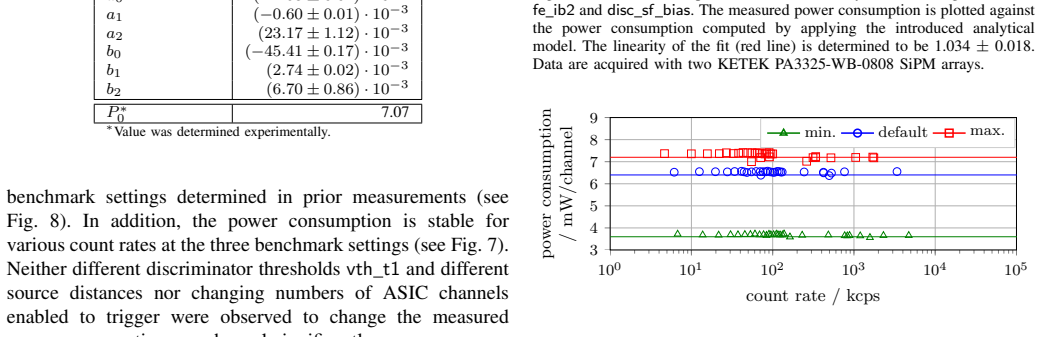
The central claim is that the TOFPET2 ASIC's power consumption is a software-tunable quantity, ranging from 3.6 mW/channel at minimum to 7.2 mW/channel at maximum, and that this variation is described by the additive model $P_{ch} = P_0 + dP_{feib1} + dP_{feib2} + dP_{discsfbias}$ (Eq. 4). Each delta is a piecewise linear or parabolic function of one configuration parameter, fitted to single-parameter scans performed with the other two parameters at zero; $P_0$ is the measured y-intercept at all-zero settings and absorbs count-rate dependence. Validation on random parameter tuples gave a fitted slope of 1.034 ± 0.018 and a negligible intercept of about 0.1 mW/channel, which the authors take as confirmation that the model works for arbitrary configurations. The paper further reports that power is stable across overvoltages from 0.75 V to 7.75 V and across count rates from about 1 kcps to 100,000 kcps, and that reducing power from maximum to minimum worsens coincidence resolution time by 20 to 40 ps while moving the effective photo-electron trigger thresholds.
Load-bearing premise
The load-bearing premise is that fe_ib1, fe_ib2, and disc_sf_bias change power consumption independently, so single-parameter curves measured with the other two at zero remain valid across all combinations; the paper states that cross-parameter interaction experiments were not performed.
Editorial extensions
If this is right
- A system designer can compute per-channel power draw for any triple of the three settings from the published fit parameters plus one measured baseline, without benchtop measurements per configuration.
- Choosing the minimum-power configuration (3.6 mW/channel) sacrifices 20 to 40 ps of coincidence resolution time relative to maximum power, while energy resolution changes by less than 0.5% absolute.
- Because photo-electron trigger levels shift with power setting, threshold calibration (e.g., vth_t1) must be redone after switching between minimum, default, and maximum power configurations.
- Measured power is stable over count rates from roughly 1 kcps to 100,000 kcps and over overvoltage from 0.75 V to 7.75 V, so the benchmark numbers are representative for realistic operation rather than single-point artifacts.
- Including the estimated 1.2 mW/channel for ASIC-FPGA communication, the total 4.8 to 8.4 mW/channel remains similar to or below other PET readout ASICs such as Triroc (10 mW/channel), STiC3 (25 mW/channel), and PETA4 (<40 mW/channel).
Reading between the lines
- A consequence the authors leave implicit is that the transportability of the fitted single-parameter curves can be established by two-parameter scans; if those scans reproduce the additive predictions, the model becomes a general design rule rather than a validation-set fit.
- The count-rate dependence sitting entirely in $P_0$ suggests a future circuit-level model that separates digital switching current from analog bias current could predict the baseline analytically and eliminate the one remaining experimental calibration step.
- The shunt-resistor metrology used here could be reapplied to other ASICs with on-board low-dropout regulators, giving system builders a comparable measure of analog front-end power that excludes FPGA and communication loads.
- For PET/MR integration, average power is only part of the story: if low-power settings also change the time structure of the current drawn on the 1.2-V line, they could affect electromagnetic interference inside the MR bore in ways the paper does not quantify.
Signed reviews
Editorial analysis
A structured set of objections, weighed in public.
Referee Report
Summary. This paper quantifies the power consumption of the TOFPET2 ASIC as a function of three software-configurable parameters: fe_ib1 (input stage impedance), fe_ib2 (discriminator noise), and disc_sf_bias (discriminator noise slew rate). The authors use a benchtop evaluation kit, measure the 1.2 V supply current via a shunt resistor inserted in place of a fuse on the FEB/D board, and report values from 3.6 to 7.2 mW/channel depending on the configuration. They propose an additive model P_ch = P0 + dP_fe_ib1 + dP_fe_ib2 + dP_disc_sf_bias with piecewise linear/parabolic fits, determine the coefficients by least-squares fits to single-parameter scans, and validate the model on a set of random parameter tuples, reporting a regression slope of 1.034 ± 0.018. They also evaluate coincidence resolution time, energy resolution, filtered count rate, satellite peak fraction, and dark-count trigger level at minimum, default, and maximum power settings, and compare the ASIC with other PET front-end ASICs.
Significance. Provided the analytic model is made reproducible, the paper is a useful engineering contribution: it establishes a tunable power-performance operating range for the TOFPET2 ASIC in a PET/MR context, and the measurement method (current sensing on the LDO input, exclusion of the FPGA line, stability checks over count rate and overvoltage) is carefully described and internally consistent. The comparison table of ASIC power consumptions and the explicit discussion of what the measured power does not include (ASIC-FPGA communication) are valuable. The paper does not claim device-level derivation; it is an empirical model, and the main limitation is that P0 must be measured for each setup and that cross-parameter interactions are not experimentally probed.
major comments (3)
- [IV.B, Eq. (6), Table II] Equation (6) defines dP_fe_ib1 using coefficient a3 for the parabolic branch (41 ≤ fe_ib1 ≤ 60), but Table II lists only a0, a1, and a2 and does not contain a3. Table II additionally lists a0, which does not appear in Eq. (6) or in Eq. (7). As printed, the model cannot be evaluated for the upper fe_ib1 range, which includes the default (fe_ib1=59) and minimum (fe_ib1=60) benchmark configurations. The authors should correct the equation/table labels and provide the complete set of coefficients.
- [IV.B, Eq. (7), Table II] With the printed values b1 = +2.74×10⁻³ mW/channel and b2 = +6.70×10⁻³ mW/channel, dP_fe_ib2 is positive and increasing over fe_ib2 ∈ [21,30]; for example, it is approximately +1.35 mW/channel at fe_ib2=30. This contradicts Fig. 5b, which shows the power consumption decreasing monotonically in fe_ib2, and Table I, which places the minimum power consumption at fe_ib2=30. The equation signs or the table entries are therefore inconsistent, and the model predictions for half of the fe_ib2 range are wrong as printed. This must be reconciled and the corrected model re-validated on the random tuples.
- [IV.B, V, and Fig. 6] The claim that the model 'can be used to compute the power consumption prior to experiments' is stronger than what the current evidence supports, because P0 must be measured experimentally for each setup and because the additive superposition of the three single-parameter effects has not been tested for interactions. The random-tuple validation in Fig. 6 is a useful check, but it uses the same setup and the same measurement method as the fits, and the tuple coverage is not reported. The authors should either extend the validation to include interaction-sensitive points (e.g., high fe_ib1 with non-zero fe_ib2 or disc_sf_bias) or explicitly restrict the claim to differential predictions once P0 is known, in the abstract as well as in Section V.
minor comments (5)
- [III.A and IV.A] Section III.A states that fe_ib1 was scanned from 0 to 60, yet Section IV.A discusses a 'systematic increase for fe_ib1 > 60' and Fig. 5a marks this with a black circle. Please clarify the actual scan range and what the black circle indicates.
- [Fig. 4 caption] The caption says 'KETEK PM3325', but the detector is referred to as 'KETEK PA3325' elsewhere in the text; this should be corrected.
- [Eq. (2)] The saturation formula is typeset ambiguously; please define the variables e and s and give the intended mathematical expression for the logarithmic term explicitly.
- [IV.B] The 'linearity of 1.034 ± 0.018' is the slope of the measured-versus-computed regression, not a coefficient of determination; the wording should be changed to 'regression slope' for clarity.
- [Table II] Table II would be more self-contained if the breakpoints of the piecewise functions (0–40/41–60 for fe_ib1 and 0–20/21–30 for fe_ib2) were included in the caption or as separate columns.
Circularity Check
No significant circularity: the additive power model is an empirical fit validated on held-out random tuples, and no load-bearing self-citation or definitional reduction is present.
full rationale
The analytical model (Eq. 4) is an explicit empirical ansatz: the dP terms are fit with least squares to one-dimensional parameter sweeps and P0 is measured at the reference tuple, with no claim that the parameters are derived from device physics. The random-tuple validation (Fig. 6) tests the additivity assumption on tuples not used in the fit, so the computed power for those tuples is not identical to the model's inputs by construction. Section V candidly states that P0 must be determined experimentally, that the model has been verified only for the present setup, and that cross-parameter interactions were not probed; these are limitations on the 'prior to experiments' wording rather than circular steps. The mismatch between Eq. (6) and Table II (undefined a3, sign inconsistencies for b1/b2) is a reproducibility/correctness flaw, not circularity. No self-citation is load-bearing and no uniqueness or ansatz is imported from prior work to force the model choice. Therefore the derivation chain is not circular.
Assumptions & free parameters
free parameters (6)
- P0 =
7.07 mW/channel (measured)
- dP_discsfbias slope f0 =
(-9.96 ± 0.03) × 10^-3 mW/channel per unit
- dP_feib1 coefficients (a0/a1/a2) =
a0=(-2.53±0.02)e-3, a1=(-0.60±0.01)e-3, a2=(23.17±1.12)e-3 mW/channel
- dP_feib2 coefficients (b0/b1/b2) =
b0=(-45.41±0.17)e-3, b1=(2.74±0.02)e-3, b2=(6.70±0.86)e-3 mW/channel
- Energy calibration factors c and s =
Not explicitly listed; fitted to 511 keV and 1274.5 keV peak positions
- Bias voltage offset Uoff =
Approx. 750 mV per channel
assumptions (4)
- domain assumption The LDO regulator's quiescent current Iq is negligible, so the average current into the LDO equals the average ASIC supply current IDD12.
- domain assumption The power contributions of the three configuration parameters are linearly independent and additive across the entire parameter space.
- domain assumption The power consumption measured on the 1.2 V line excludes ASIC-FPGA communication, and the estimated 1.2 mW/channel overhead from a 30 mA reference on the 2.5 V line is valid.
- domain assumption The measured power consumption remains stable across count rates and overvoltages, so benchmark values generalize to the conditions tested.
Cite this review
Pith. "Pith review of Investigation of the Power Consumption of the PETsys TOFPET2 ASIC." pith.science (2026). https://pith.science/paper/JZS2ZOR7
@misc{pith2026190805878,
  author       = {Pith},
  title        = {Pith review of: Investigation of the Power Consumption of the PETsys TOFPET2 ASIC},
  year         = {2026},
  howpublished = {\url{https://pith.science/paper/JZS2ZOR7}},
  note         = {Machine review of arXiv:1908.05878}
}
read the original abstract
In state-of-the-art positron emission (PET) tomography systems, application-specific integrated circuits (ASICs)are commonly used to precisely digitize the signals of analog silicon photo-multipliers (SiPMs). However, when operating PET electronics in a magnetic resonance (MR) system, one faces the challenge of mutual interference of these imaging techniques. To prevent signal deterioration along long analog signal lines, PET electronics with a low power consumption digitizing the signals close to the SiPMs are preferred. In this study, we evaluate the power consumption of the TOFPET2 ASIC. Its power consumption ranges from 3.6 to 7.2 mW/channel as a function of the input stage impedance and discriminator noise settings. We present an analytical model allowing to compute the power consumption of a given ASIC configuration. The configured input stage impedance and discriminator noise have an impact on the coincidence resolution time, energy resolution, and photon trigger level. Since the TOFPET2 ASIC delivers state-of-the-art performance with a power consumption similar or even lower than other ASICs typically used for PET applications, it is a favorable candidate to digitize the signals of SiPMs in future simultaneous PET/MR systems.
Figures

Figures from the paper (7 more)



Forward citations
Cited by 1 Pith paper
-
PETAT -- An ASIC for Simple and Efficient Readout of Large PET Scanners
PETAT introduces a time-sorted daisy-chain readout and serial powering for PET SiPM ASICs, replacing per-module FPGAs and reducing supply current.
Reference graph
Works this paper leans on
-
[1]
ADV ANCES IN TIME-OF-FLIGHT PET,
S. Surti et al. , “ADV ANCES IN TIME-OF-FLIGHT PET,” Physica Medica, vol. 32, no. 1, pp. 12–22, 2016. DOI: 10.1016/j.ejmp.2015. 12.007
-
[2]
RECENT DEVELOPMENTS IN TIME-OF- FLIGHT PET,
S. Vandenberghe et al., “RECENT DEVELOPMENTS IN TIME-OF- FLIGHT PET,” EJNMMI physics , vol. 3, no. 1, 2016. DOI: 10.1186/ s40658-016-0138-3
work page 2016
-
[3]
Phelps, PET: Physics, Instrumentation, and Scanners
M. Phelps, PET: Physics, Instrumentation, and Scanners . Springer, 2006
work page 2006
-
[4]
W. A. Weber et al. , “POSITRON EMISSION TOMOGRAPHY IN NON-SMALL-CELL LUNG CANCER: PREDICTION OF RE- SPONSE TO CHEMOTHERAPY BY QUANTITATIVE ASSESS- MENT OF GLUCOSE USE,” The Journal of Clinical Oncology , vol. 21, no. 14, pp. 2651–2657, 2003. DOI: 10.1200/JCO.2003.12.004
-
[5]
BRAIN PET IN THE DIAGNOSIS OF ALZHEIMER’S DISEASE,
C. Marcus et al. , “BRAIN PET IN THE DIAGNOSIS OF ALZHEIMER’S DISEASE,”NIH-PA Author Manuscript, vol. 39, no. 10, e413–e426, 2014. DOI: 10.1097/RLU.0000000000000547
-
[6]
MYOCARDIAL PERFUSION IMAGING WITH PET,
R. Nakazato et al., “MYOCARDIAL PERFUSION IMAGING WITH PET,” NIH-PA Author Manuscript, vol. 5, no. 1, pp. 35–46, 2013. DOI: 10.2217/iim.13.1
-
[7]
Development of analog solid-state photo-detectors for Positron Emis- sion Tomography,
“Development of analog solid-state photo-detectors for Positron Emis- sion Tomography,” Nuclear Instruments and Methods in Physics Research Section A: Accelerators, Spectrometers, Detectors and Asso- ciated Equipment, vol. 809, pp. 140–148, 2016, Advances in detectors and applications for medicine. DOI: 10.1016/j.nima.2015.09.114
-
[8]
TIME RESOLUTION DETERIORATION WITH INCREASING CRYSTAL LENGTH IN A TOF-PET SYS- TEM,
S. Gundacker et al. , “TIME RESOLUTION DETERIORATION WITH INCREASING CRYSTAL LENGTH IN A TOF-PET SYS- TEM,” Nuclear Instruments and Methods in Physics Research Section A: Accelerators, Spectrometers, Detectors and Associated Equipment , vol. 737, pp. 92–100, 2014. DOI: https://doi.org/10.1016/j.nima.2013. 11.025
Show all 66 references
-
[9]
UPDATE ON TIME-OF-FLIGHT PET IMAGING,
S. Surti, “UPDATE ON TIME-OF-FLIGHT PET IMAGING,” J Nucl Med, vol. 56, no. 1, pp. 98–105, Jan. 2015. DOI: 10.2967/jnumed. 114.145029
2015 doi
-
[10]
127, 91052 Erlangen, Germany, Jun
BIOGRAPH VISION TECHNICAL FLYER , Siemens Healthcare, Siemens Healthcare GmbH, Henkestr. 127, 91052 Erlangen, Germany, Jun. 2018
2018
-
[11]
HIGH-FREQUENCY SIPM READOUT ADV ANCES MEASURED COINCIDENCE TIME RESOLUTION LIMITS IN TOF-PET,
S. Gundacker et al. , “HIGH-FREQUENCY SIPM READOUT ADV ANCES MEASURED COINCIDENCE TIME RESOLUTION LIMITS IN TOF-PET,” Physics in Medicine & Biology , vol. 64, no. 5, p. 055 012, Feb. 2019. DOI: 10.1088/1361-6560/aafd52
2019 doi
-
[12]
Pushing the limits in Time-Of-Flight PET imaging,
P. Lecoq, “Pushing the limits in Time-Of-Flight PET imaging,” IEEE Transactions on Radiation and Plasma Medical Sciences , vol. PP, pp. 1–1, Nov. 2017. DOI: 10.1109/TRPMS.2017.2756674
2017
-
[13]
A 64-CHANNEL ASIC FOR TOFPET APPLI- CATIONS,
M. D. Rolo et al. , “A 64-CHANNEL ASIC FOR TOFPET APPLI- CATIONS,” 2012 IEEE Nuclear Science Symposium and Medical Imaging Conference Record (NSS/MIC) , pp. 1460–1464, 2012
2012
-
[14]
A DEDICATED READOUT ASIC FOR TIME- OF-FLIGHT POSITRON EMISSION TOMOGRAPHY USING SILI- CON PHOTOMULTIPLIER (SIPM),
H. Chen et al. , “A DEDICATED READOUT ASIC FOR TIME- OF-FLIGHT POSITRON EMISSION TOMOGRAPHY USING SILI- CON PHOTOMULTIPLIER (SIPM),” in Nuclear Science Symposium and Medical Imaging Conference (NSS/MIC), 2014 IEEE , IEEE, 2014, pp. 1–5. DOI: 10.1109/NSSMIC.2014.7431045
2014
-
[15]
ASIC DEVELOPMENT FOR SIPM READOUT,
F. Corsi et al. , “ASIC DEVELOPMENT FOR SIPM READOUT,” Journal of Instrumentation , vol. 4, 2009. DOI: 10.1088/1748-0221/4/ 03/P03004
2009 doi
-
[16]
FAST SELF TRIGGERED MULTI CHANNEL READOUT ASIC FOR TIME- AND ENERGY MEASUREMENT,
P. Fischer et al. , “FAST SELF TRIGGERED MULTI CHANNEL READOUT ASIC FOR TIME- AND ENERGY MEASUREMENT,” IEEE Transactions on Nuclear Science , vol. 53, no. 3, pp. 1153–1158,
-
[17]
STIC – A MIXED MODE CHIP FOR SIPM TOF APPLICATIONS,
W. Shen et al. , “STIC – A MIXED MODE CHIP FOR SIPM TOF APPLICATIONS,” 2012 IEEE Nuclear Science Symposium and Medical Imaging Conference Record (NSS/MIC) , vol. N14-37, pp. 877–881, 2012
2012
-
[18]
Performance Measurements of the SAFIR Prototype Detector With the STiC ASIC Readout,
M. Ahnen et al., “Performance Measurements of the SAFIR Prototype Detector With the STiC ASIC Readout,” IEEE Transactions on Radiation and Plasma Medical Sciences , vol. 2, no. 3, pp. 250–258, May 2018. DOI: 10.1109/TRPMS.2018.2797484
2018
-
[19]
PETIROC, A NEW FRONT-END ASIC FOR TIME OF FLIGHT APPLICATION,
J. Fleury et al. , “PETIROC, A NEW FRONT-END ASIC FOR TIME OF FLIGHT APPLICATION,” 2013 IEEE Nuclear Science Symposium and Medical Imaging Conference (2013 NSS/MIC) , 2013. DOI: 10.1109/NSSMIC.2013.6829018
2013
-
[20]
PETA4: A MULTI-CHANNEL TDC/ADC ASIC FOR SIPM READOUT,
I. Sacco et al. , “PETA4: A MULTI-CHANNEL TDC/ADC ASIC FOR SIPM READOUT,” Journal of Instrumentation , vol. 8, 2013. DOI: 10.1088/1748-0221/8/12/C12013
2013 doi
-
[21]
TRIROC: A MULTI-CHANNEL SIPM READ- OUT ASIC FOR PET/PET-TOF APPLICATION,
S. Ahmad et al. , “TRIROC: A MULTI-CHANNEL SIPM READ- OUT ASIC FOR PET/PET-TOF APPLICATION,”IEEE Transactions on Nuclear Science , vol. 62, no. 3, pp. 664–668, 2015. DOI: 10.1109/ TNS.2015.2397973
2015
-
[22]
TRIROC, A VERSATILE 64-CHANNEL SIPM READOUT ASIC FOR TIME-OF-FLIGHT PET,
S. Ahmad et al. , “TRIROC, A VERSATILE 64-CHANNEL SIPM READOUT ASIC FOR TIME-OF-FLIGHT PET,” IEEE Nuclear Science Symposium, Medical Imaging Conference and Room- Temperature Semiconductor Detector Workshop (NSS/MIC/RTSD) ,
-
[23]
STIC3 - SILICON PHOTOMULTIPLIER TIM- ING CHIP WITH PICOSECOND RESOLUTION,
V . Stankova et al. , “STIC3 - SILICON PHOTOMULTIPLIER TIM- ING CHIP WITH PICOSECOND RESOLUTION,” Elsevier: Nuclear Instruments and Methods in Physics Research A , vol. 787, pp. 284– 287, 2015. DOI: 10.1016/j.nima.2014.12.073
2015 doi
-
[24]
TOFPET ASIC FOR PET APPLICATIONS,
M. D. Rolo et al. , “TOFPET ASIC FOR PET APPLICATIONS,” Journal of Instrumentation , vol. 8, 2013. DOI: 10.1088/1748-0221/8/ 02/C02050
2013 doi
-
[25]
THE CURRENT MODE TIME-OVER- THRESHOLD ASIC FOR A MPPC MODULE IN A TOF-PET SYSTEM,
T. Orita et al. , “THE CURRENT MODE TIME-OVER- THRESHOLD ASIC FOR A MPPC MODULE IN A TOF-PET SYSTEM,” Nuclear Instruments and Methods in Physics Research Section A: Accelerators, Spectrometers, Detectors and Associated Equipment, 2017. DOI: 10.1016/j.nima.2017.11.097
2017 doi
-
[26]
A Compact Detector Module Design Based on FlexToT ASICs for Time-of-Flight PET-MR,
J. M. Cela et al. , “A Compact Detector Module Design Based on FlexToT ASICs for Time-of-Flight PET-MR,” IEEE Transactions on Radiation and Plasma Medical Sciences , vol. 2, no. 6, pp. 549–553, Nov. 2018. DOI: 10.1109/TRPMS.2018.2870927
2018
-
[27]
A High Dynamic Range ASIC for Time of Flight PET with monolithic crystals,
S. G. Fern ´andez et al. , “A High Dynamic Range ASIC for Time of Flight PET with monolithic crystals,” 2019. DOI: 10.22323/1.343. 0085
2019 doi
-
[28]
Fleury, PETIROC2A : NEW MEASUREMENT RESULTS ON F AST TOF SIPM READ-OUT CHIP , Talk at TIPP 2017, Beijing, China, May 2017
J. Fleury, PETIROC2A : NEW MEASUREMENT RESULTS ON F AST TOF SIPM READ-OUT CHIP , Talk at TIPP 2017, Beijing, China, May 2017
2017
-
[29]
MULTI-CHANNEL READOUT ASIC FOR TOF- PET,
P. Fischer et al. , “MULTI-CHANNEL READOUT ASIC FOR TOF- PET,” IEEE Nuclear Science Symposium Conference Record , vol. M11-140, pp. 2523–2527, 2006
2006
-
[30]
PERFORMANCE OF FBK SIPMS COUPLED TO PETA3 READ-OUT ASIC FOR PET APPLICATION,
C. Piemonte et al. , “PERFORMANCE OF FBK SIPMS COUPLED TO PETA3 READ-OUT ASIC FOR PET APPLICATION,” Elsevier: Nuclear Instruments and Methods in Physics Research A , vol. 718, pp. 345–346, 2012. DOI: 10.1016/j.nima.2012.10.012
2012 doi
-
[31]
A COMPACT, HIGH-DENSITY GAMMA- DETECTION MODULE FOR TIME-OF-FLIGHT MEASURE- MENTS IN PET APPLICATIONS,
I. Sacco et al. , “A COMPACT, HIGH-DENSITY GAMMA- DETECTION MODULE FOR TIME-OF-FLIGHT MEASURE- MENTS IN PET APPLICATIONS,” Nuclear Instruments and Meth- ods in Physics Research Section A Accelerators Spectrometers Detec- tors and Associated Equipment , vol. 824, 2015. DOI: 10....
2015 doi
-
[32]
MEASUREMENTS WITH A PET COINCIDENCE SETUP BASED ON THE PETA5 ASIC AND FBK RGB-HD SIPMS,
D. Schug et al., “MEASUREMENTS WITH A PET COINCIDENCE SETUP BASED ON THE PETA5 ASIC AND FBK RGB-HD SIPMS,” in 2017 IEEE Nuclear Science Symposium and Medical Imaging Conference (NSS/MIC) , IEEE, 2017, pp. 1–3. DOI: 10.1109/ NSSMIC.2017.8532761
2017
-
[33]
EXPERIMENTAL RESULTS WITH TOFPET2 ASIC FOR TIME-OF-FLIGHT APPLICATIONS,
R. Bugalho et al. , “EXPERIMENTAL RESULTS WITH TOFPET2 ASIC FOR TIME-OF-FLIGHT APPLICATIONS,” Nuclear Instru- ments and Methods in Physics Research Section A: Accelerators, Spectrometers, Detectors and Associated Equipment , 2017. DOI: 10. 1016/j.nima.2017.11.034
2017
-
[34]
1.2) , 1.2, PETsys Electronics S.A., PETsys Electronics SA, Taguspark - Lisboa Science and Technology Park, Edificio Tecnologia I, 26, 2740-257 PORTO SALVO, Portugal, Feb
TOFPET ASIC V1 – SHORT DATA SHEET (REV . 1.2) , 1.2, PETsys Electronics S.A., PETsys Electronics SA, Taguspark - Lisboa Science and Technology Park, Edificio Tecnologia I, 26, 2740-257 PORTO SALVO, Portugal, Feb. 2014
2014
-
[35]
TOFPET 2 SIPM READOUT ASIC (REV .2 ) , 1st ed., PETsys Elec- tronics S.A., PETsys Electronics SA, Taguspark - Lisboa Science and Technology Park, Edificio Tecnologia I, 26, 2740-257 PORTO SALVO, Portugal, Jul. 2018
2018
-
[36]
EASIROC, AN EASY AND VERSATILE READ- OUT DEVICE FOR SIPM,
S. Callier et al. , “EASIROC, AN EASY AND VERSATILE READ- OUT DEVICE FOR SIPM,” Physics Procedia , vol. 37, pp. 1569– 1576, 2012, Proceedings of the 2nd International Conference on Technology and Instrumentation in Particle Physics (TIPP 2011). DOI: 10.1016/j.phpro.2012.02.486
2012 doi
-
[37]
MR-compatibility assessment of the first preclin- ical PET-MRI insert equipped with digital silicon photomultipliers,
J. Wehner et al. , “MR-compatibility assessment of the first preclin- ical PET-MRI insert equipped with digital silicon photomultipliers,” Physics in Medicine and Biology , vol. 60, no. 6, pp. 2231–2255, Feb
-
[38]
S. Vandenberghe et al., “PET-MRI: A REVIEW OF CHALLENGES AND SOLUTIONS IN THE DEVELOPMENT OF INTEGRATED ACCEPTED FOR PUBLICATION IN: IEEE TRPMS - SPECIAL ISSUE PSMR 2019 - 8TH CONFERENCE ON PET/MR AND SPECT/MR 11 MULTIMODALITY IMAGING,” Physics in Medicine and Biology , vol. 6...
2019 doi
-
[39]
PET PERFORMANCE AND MRI COMPATI- BILITY EV ALUATION OF A DIGITAL, TOF-CAPABLE PET/MRI INSERT EQUIPPED WITH CLINICAL SCINTILLATORS,
D. Schug et al. , “PET PERFORMANCE AND MRI COMPATI- BILITY EV ALUATION OF A DIGITAL, TOF-CAPABLE PET/MRI INSERT EQUIPPED WITH CLINICAL SCINTILLATORS,”Physics in Medicine and Biology, vol. 60, no. 18, p. 7045, 2015. DOI: 10.1088/ 0031-9155/60/18/7045
2015
-
[40]
TOFPET2 ASIC SIPM READOUT SYSTEM - HARDWARE USER GUIDE (V1.5) , v1.5, PETsys Electronics SA., Dec. 2018
2018
-
[41]
DEVELOPMENT OF AN MRI- COMPATIBLE DIGITAL SIPM DETECTOR STACK FOR SIMUL- TANEOUS PET/MRI,
P. M. D ¨uppenbecker et al. , “DEVELOPMENT OF AN MRI- COMPATIBLE DIGITAL SIPM DETECTOR STACK FOR SIMUL- TANEOUS PET/MRI,” Biomed Phys Eng Express , vol. 2, no. 1, p. 015 010, Feb. 2016. DOI: 10.1088/2057-1976/2/1/015010
2016 doi
-
[42]
MR COMPATIBILITY ASPECTS OF A SILI- CON PHOTOMULTIPLIER-BASED PET/RF INSERT WITH INTE- GRATED DIGITISATION,
B. Weissler et al. , “MR COMPATIBILITY ASPECTS OF A SILI- CON PHOTOMULTIPLIER-BASED PET/RF INSERT WITH INTE- GRATED DIGITISATION,” Physics in Medicine and Biology , vol. 59, no. 17, pp. 5119–5139, Aug. 2014. DOI: 10.1088/0031-9155/59/ 17/5119
2014 doi
-
[43]
Website, Accessed: 2019-02-27, PETsys Electronics S.A., 2019
2019
-
[44]
TOFPET2 ASIC EVALUATION KIT - HARDWARE USER GUIDE (V1.2), v1.2, PETsys Electronics SA., May 2018
2018
-
[45]
Investigating the impact of the power consumption on the ASIC performance and the dark count rate, a calibration was run at each power consumption setting
was run for each investigated SiPM type at default ASIC configuration with an overvoltage of 4 V and vth t1 = 20 , vth t2 = 20, and vth e = 15. Investigating the impact of the power consumption on the ASIC performance and the dark count rate, a calibration was run at each power...
2019
-
[46]
PETSYS TOF ASIC EVALUATION KIT (FLYER) , v15, PETsys Elec- tronic S.A., Oct. 2018
2018
-
[48]
PERSONAL COMMUNICATION,
PETsys Electronics S.A., “PERSONAL COMMUNICATION,” Emails, conferences, 2018
2018
-
[49]
TOFPET2 ASIC EVALUATION KIT - SOFTWARE USER GUIDE V2018.04, v2018.04, PETsys Electronics SA., Apr. 2018
2018
-
[50]
Radioactive Sources - Multimodal Application Guide , Accessed: 2019-10-04, Eckert & Ziegler, 2019
2019
-
[51]
TOFPET2 ASIC EVALUATION KIT - SOFTWARE USER GUIDE V2019.01, v2019.01, PETsys Electronics SA., Jan. 2019
2019
-
[52]
A COMPARATIVE STUDY OF THE TIME PER- FORMANCE BETWEEN NINO AND FLEXTOT ASICS,
I. Sarasola et al., “A COMPARATIVE STUDY OF THE TIME PER- FORMANCE BETWEEN NINO AND FLEXTOT ASICS,” Journal of Instrumentation , vol. 12, P04016, 2017. DOI: 10.1088/1748-0221/ 12/04/P04016
2017 doi
-
[53]
Initial Measurements with the PETsys TOFPET2 ASIC Evaluation Kit and a Characterization of the ASIC TDC,
D. Schug et al. , “Initial Measurements with the PETsys TOFPET2 ASIC Evaluation Kit and a Characterization of the ASIC TDC,” IEEE Transactions on Radiation and Plasma Medical Sciences , vol. 3, no. 4, pp. 444–453, Jul. 2019. DOI: 10.1109/TRPMS.2018.2884564
2019
-
[54]
HRFLEXTOT HIGH RESOLUTION FLEXIBLE TIME OVER THRESHOLD ASIC USER MANUAL , 1.1, ICCUB Instiute of Cosmos Sciences/Universitat de Barcelona, Oct. 2018
2018
-
[55]
Gasc ´on et al
D. Gasc ´on et al. , A High Dynamic Range ASIC for Time of Flight PET with pixelated and monolithic crystals , Talk at NSS-MIC 2019, Manchester, United Kingdom, Oct. 2019
2019
-
[56]
NINO: AN ULTRAFAST LOW-POWER FRONT-END AMPLIFIER DISCRIMINATOR FOR THE TIME- OF-FLIGHT DETECTOR IN THE ALICE EXPERIMENT,
F. Anghinolfi et al. , “NINO: AN ULTRAFAST LOW-POWER FRONT-END AMPLIFIER DISCRIMINATOR FOR THE TIME- OF-FLIGHT DETECTOR IN THE ALICE EXPERIMENT,” IEEE TRANSACTIONS ON NUCLEAR SCIENCE , vol. 51, no. 5, pp. 1974– 1978, Oct. 2004. DOI: 10.1109/TNS.2004.836048
1974
-
[57]
FLEXTOT - CURRENT MODE ASIC FOR READOUT OF COMMON CATHODE SIPM ARRAYS,
A. Comerma et al. , “FLEXTOT - CURRENT MODE ASIC FOR READOUT OF COMMON CATHODE SIPM ARRAYS,”2013 IEEE Nuclear Science Symposium and Medical Imaging Conference (2013 NSS/MIC), 2013. DOI: 10.1109/nssmic.2013.6829761
2013
-
[58]
CHARACTERIZATION OF TOF-PET DE- TECTORS BASED ON MONOLITHIC BLOCKS AND ASIC- READOUT,
E. Lamprou et al. , “CHARACTERIZATION OF TOF-PET DE- TECTORS BASED ON MONOLITHIC BLOCKS AND ASIC- READOUT,” ArXiv preprint arXiv:1806.08715 , 2018
2018 arXiv
-
[59]
DEVELOPMENT OF A 64-CHANNEL READOUT ASIC FOR AN 8X8 SSPM ARRAY FOR PET AND TOF-PET APPLICATIONS,
X. Zhu et al. , “DEVELOPMENT OF A 64-CHANNEL READOUT ASIC FOR AN 8X8 SSPM ARRAY FOR PET AND TOF-PET APPLICATIONS,”IEEE TRANSACTIONS ON NUCLEAR SCIENCE ,
-
[60]
High-Energy Photon Detection With LYSO Crystals,
M. Thiel et al., “High-Energy Photon Detection With LYSO Crystals,” IEEE Transactions on Nuclear Science , vol. 55, no. 3, pp. 1425–1429, Jun. 2008. DOI: 10.1109/TNS.2008.922838
2008
-
[61]
V ALIDATION OF A HIGHLY INTEGRATED SIPM READOUT SYSTEM WITH A TOF-PET DEMONSTRA- TOR,
T. Niknejad et al. , “V ALIDATION OF A HIGHLY INTEGRATED SIPM READOUT SYSTEM WITH A TOF-PET DEMONSTRA- TOR,” Journal of Instrumentation , vol. 11, 2016. DOI: 10.1088/1748- 0221/11/12/P12003
2016 doi
-
[62]
A Digital Preclinical PET/MRI Insert and Initial Results,
B. Weissler et al. , “A Digital Preclinical PET/MRI Insert and Initial Results,” IEEE Transactions on Medical Imaging , vol. 34, no. 11, pp. 2258–2270, Nov. 2015. DOI: 10.1109/TMI.2015.2427993
2015
-
[64]
DOI: 10.1109/TNS.2016.2518808
2016
-
[66]
PET/MRI INSERT USING DIGITAL SIPMS: INVESTIGATION OF MR-COMPATIBILITY,
J. Wehner et al. , “PET/MRI INSERT USING DIGITAL SIPMS: INVESTIGATION OF MR-COMPATIBILITY,”Nuclear Instruments and Methods in Physics Research Section A: Accelerators, Spectrom- eters, Detectors and Associated Equipment , vol. 734, pp. 116–121, 2014, PSMR2013 - PET-MR and SPEC...
2014 doi
-
[2009]
DOI: 10.1109/TNS.2008.2008807
2008
-
[2015]
DOI: 10.1088/0031-9155/60/6/2231
-
[2016]
DOI: 10.1109/NSSMIC.2016.8069882
2016
Reviewed August 14, 2026 · model on record in the stance chip above.
Discussion (0). Continue with ORCID to comment.