REVIEW 3 major objections 5 minor 28 references
Design Automation and Optimization Methodology for Electric Multicopter UAVs
T0 review · 3 major / 5 minor · reviewed 2026-08-14 · deepseek-v4-flash
Pith's one-line read A two-stage database method converts multicopter requirements into a sorted, buildable design in under 20 ms.
desk verdict A useful two-stage multicopter design tool whose altitude-conversion step contains a sign error in Eq. (40) that needs a mandatory fix. read the letter →
The pith
A machine-rendered reading of the paper's core claim, the machinery that carries it, and where it could break.
The reading
What carries the argument
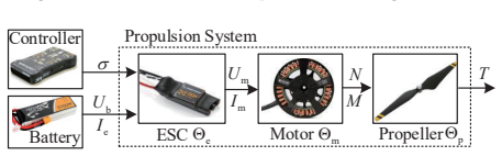
The load-bearing object is the propulsion combination database $\Phi_{mep}$. Each entry stores a motor, its chosen ESC and propeller, battery voltage, propeller diameter, KV value, mass, full-throttle thrust, current, speed, motor current limit, and the coefficients $k_{t0}, k_{t1}, k_{t2}$ of the fitted curve $I_e = k_{t2}T^2 + k_{t1}T + k_{t0}$ relating ESC input current to output thrust. This quadratic makes hovering current computable from a single thrust target, which feeds the discharge-time equation $t_{dis} = \alpha_b \, 60 \rho_b m_{battery} / (U_b I_{bHover})$. The online screening criterion $|t_{dis} - \hat{t}_{fly}| / \hat{t}_{fly} \le \varepsilon_t$ keeps candidate combinations whose predicted hovering time matches the requirement, and the ranked objective $J = \sum_{i=1}^7 k_i X_i / \overline{X_i}$ finally orders designs by size, weight, requirement agreement, hovering efficiency, battery voltage and capacity, and safety margin.
What would settle it
Weigh the airframe and battery of the validation quadcopter separately and compare the measured airframe fraction to 0.19; then recompute the predicted hover time with the measured fraction and see whether the discharge-time equation moves toward or away from the observed flight time.
Extended reading notes
Core claim
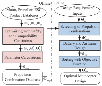
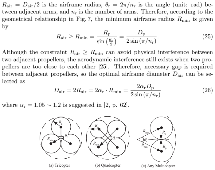
The paper's central claim is that multicopter design optimization can be decomposed into an offline product-selection problem and an online sizing problem. For each motor in a product database, the offline algorithm chooses the ESC and propeller that maximize a normalized score of full-throttle thrust, thrust efficiency, and propulsion-system mass, subject to safety and compatibility constraints; that winning combination, together with measured properties and a fitted quadratic thrust-current curve, becomes a row of a combination database. Online, each stored combination is tested against a design requirement by converting the required hovering thrust to battery current and predicting discharge time, and combinations whose predicted hovering time falls within a tolerance of the requested value proceed to battery sizing and airframe-diameter sizing from propeller geometry. Predicted performance is calibrated by experimental data, so that 'optimal' means best among tested, buildable combinations rather than best in an idealized model. The paper validates the pipeline on a quadcopter close to the F450 class and reports that the online stage completes in less than 20 ms on a large database.
Load-bearing premise
Every design inherits a fixed airframe weight fraction of 0.19, so battery mass is whatever remains after subtracting payload and propulsion mass from the total weight implied by the thrust ratio; if the real frame is lighter or heavier than that assumed share, predicted hover time shifts systematically.
Editorial extensions
If this is right
- A designer can specify hovering time, payload, thrust ratio, propeller count, altitude, and battery type and receive a component list, battery parameters, airframe diameter, and expected performance in a single automated run rather than by trial and error.
- The same calibrated database works across altitudes because the paper derives density conversions for full-throttle thrust and hovering current, so test-bench data taken at one air density can be reused.
- Online computation cost is set by the size of the preselected propulsion database, not by the product of all motor, ESC, propeller, battery, and airframe choices, which is what removes the hours-to-days search times of earlier approaches.
- The tool's output is built to be assemblable: components must pass safety voltage and current limits and manufacturer compatibility, and the airframe diameter is chosen with geometric and aerodynamic clearance between propellers.
Reading between the lines
- Beyond the paper, the fixed airframe fraction could be turned into an input or a lookup table by material and size; doing so would remove the main parameter that controls battery mass in the residual-weight equation.
- Beyond the paper, the same offline/online split transfers to coaxial layouts or other air vehicles as long as the propulsion performance model and the screening equations are replaced accordingly.
- A direct test of the curve-fit assumption would be to compute residual errors of the quadratic fit across all database entries; if residuals grow for very large or high-KV motors, the fit order or a piecewise model would need extending.
Signed reviews
Editorial analysis
A structured set of objections, weighed in public.
Referee Report
Summary. The paper proposes a two-stage design automation method for electric multicopters. An offline algorithm constructs a database of motor-ESC-propeller combinations using experimental or manufacturer test data, with thrust-current curves fitted by second-order polynomials. An online algorithm takes design requirements (hover time, payload, thrust ratio, propeller number, air density/altitude, battery type), computes battery mass and airframe diameter for each combination, screens combinations by hover-time error, and ranks the survivors with a weighted objective function. The method is validated with one test-bench case and compared with brute-force search. The stated advantages are high precision and sub-20-ms computation.
Significance. If the method works as described, it offers a practical design tool: the offline/online separation is a reasonable way to move expensive evaluations out of the interactive loop, and using component test data for calibration addresses a real limitation of purely model-based design. The core weight decomposition and battery-discharge equations are internally consistent, and the target hover time is used only as a screening criterion, so the approach is not circular. The paper also provides a public database and online toolbox, which strengthens reproducibility. However, the altitude-conversion error in Appendix B and the limited validation mean the precision and altitude-handling claims are not yet established as written.
major comments (3)
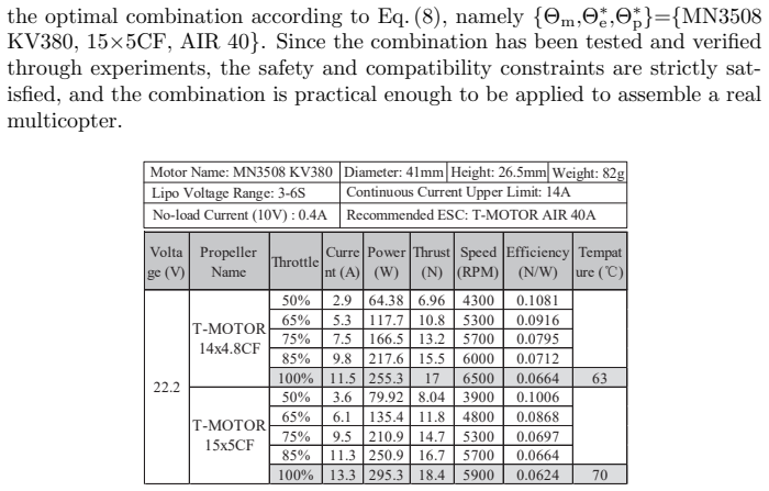
- [Appendix B, Eq. (40)] The quadratic in Eq. (38), K_N ρ N^2 + (1/K_V) N = U_b, has positive root N* = [−1 + sqrt(1 + 4 K_V^2 K_N U_b ρ)] / (2 K_V K_N ρ). Equation (40) writes sqrt(4 K_V^2 K_N U_b ρ_hat − 1), with a minus sign inside the radical. For the manuscript's own example (Section 3.3: K_V=380, U_b=22.2, N*=5900, ρ=1.2), the argument is negative, so Eq. (40) gives no real positive rotating speed. Since Eqs. (42), (48), and (50) all use this N*_hat, the altitude design requirement (input ρ_hat) is not handled correctly as written. The sign should be corrected to plus and the altitude-conversion examples re-run.
- [Section 5.2, Table 2] The experimental verification consists of a single test-bench case comparing the website prediction (1.48 kg, 17.1 min, 0.5 kg payload, 4600 mAh) with one assembled multicopter (1.55 kg, 18 min, 0.55 kg, 5000 mAh). No repeated trials, measurement uncertainty, or environmental conditions are reported. Given that the online algorithm relies on fixed empirical constants (α_air=0.19, α_b=0.9, I_other≈0.5 A, and the fitted kt coefficients), a single close agreement is insufficient to substantiate the repeated claim of 'high precision.' Additional trials or a bounded sensitivity analysis are needed.
- [Section 4.1.1, Eqs. (13)-(16)] The battery mass is computed as the residual after fixing α_air=0.19, but the cited source [24] gives a range 0.08–0.40 for the airframe weight ratio. Because mbattery enters the hover-time calculation through Eq. (20), an actual frame at either end of this range would shift the predicted tdis substantially even if the propulsion database is exact. The paper does not report how sensitive the final design ranking is to α_air (or to α_b and I_other); please add a sensitivity study or, failing that, downgrade the precision claims accordingly.
minor comments (5)
- [Eq. (27)] Equation (27) uses X_i for both the evaluation index and the normalizing parameter; the ratio should be written X_i / \bar{X}_i to avoid confusion.
- [Section 5.2 and Conclusion] The phrase 'The eight most optimal eight multicopter design results' repeats 'eight,' and the conclusion states 'more than 2000 items' while Section 5.2 refers to 'more than 200 motors' and a database of 'more than 1500' combinations; please reconcile these numbers.
- [Throughout] The phrase 'brutal search method' should be 'brute-force search method' for consistency with Algorithm 1.
- [Eq. (21)] The tolerance threshold ε_t is introduced without a recommended value or selection rule; the authors should indicate a default and show how it affects the set of accepted designs.
- [Figure 2 caption] The caption states 'Figs. 2(a)(b)(c) are of the common form and Figs. 2(a)(b)(c) are of the coaxial form'; the second list should refer to panels (d), (e), and (f).
Circularity Check
No significant circularity: the design outputs follow from a database search over externally calibrated component data, and the target requirements are used as screening inputs rather than fitted parameters.
full rationale
The derivation chain is self-contained. Offline, the propulsion database stores measured or manufacturer-published full-throttle values and second-order thrust-current fits (Eq. 11) calibrated to test-bench data; online, Eqs. (12)-(20) compute battery mass, hovering current, and discharge time from the chosen propulsion combination and the fixed airframe mass fraction of Ref. [24]. The desired hover time enters only as the screening threshold Eq. (21), not as a parameter fitted to obtain tdis. Similarly, the desired payload and thrust ratio are inputs used in the weight decomposition (Eqs. 14-16), which is design synthesis rather than an empirical prediction. The altitude remap in Appendices B-C uses the motor/propeller models and is checked against a separate F450 test bench (Table 2), so the validation is not constructed from the same fitted values. The paper's prior work [14, 15] supplies component models and database-generation tools, but the central optimization claim does not reduce to those citations, and no equation makes an output equal to an input by construction. The sign error in Eq. (40) is a genuine correctness concern for altitude conversion, but it is not a circularity and therefore does not affect this score.
Assumptions & free parameters
free parameters (7)
- airframe weight ratio alpha_air =
0.19 (range 0.08-0.40)
- battery discharge capacity ratio alpha_b =
0.9
- battery current safety margin alpha_Ib =
>= 1.5
- propeller clearance factor alpha_r =
1.05 to 1.2
- other current consumption I_other =
0.5 A
- second-order current-thrust coefficients kt0, kt1, kt2 =
example: 0.0262, 0.2559, -0.2349
- objective normalizing parameters Xbar_i and weights k_i =
example Xbar = {0.45,1.5,1,11.5,12,5000,0.65}, default k_i = 1
assumptions (6)
- domain assumption Total propeller thrust equals multicopter weight in hover (Eq. 2).
- domain assumption Airframe mass is proportional to total multicopter mass with alpha_air = 0.19 (Eq. 13).
- ad hoc to paper The thrust-current curve is a second-order polynomial (Eq. 11).
- standard math Motor steady-state DC model (Eqs. 31-33) and propeller model (Eqs. 34-35).
- domain assumption Motor no-load voltage drop Im0*Rm is negligible (Eq. 37).
- domain assumption Battery power density is constant per battery type, e.g., 240 Wh/kg for LiPo (Eq. 19).
Cite this review
Pith. "Pith review of Design Automation and Optimization Methodology for Electric Multicopter UAVs." pith.science (2026). https://pith.science/paper/TCHOBIKW
@misc{pith2026190806301,
  author       = {Pith},
  title        = {Pith review of: Design Automation and Optimization Methodology for Electric Multicopter UAVs},
  year         = {2026},
  howpublished = {\url{https://pith.science/paper/TCHOBIKW}},
  note         = {Machine review of arXiv:1908.06301}
}
read the original abstract
The traditional multicopter design method usually requires a long iterative process to find the optimal design based on given performance requirements. The method is uneconomical and inefficient. In this paper, a practical method is proposed to automatically calculate the optimal multicopter design according to the given design requirements including flight time, altitude, payload capacity, and maneuverability. The proposed method contains two algorithms: an offline algorithm and an online algorithm. The offline algorithm finds the optimal components (propeller and electronic speed controller) for each motor to establish its component combination, and subsequently, these component combinations and their key performance parameters are stored in a combination database. The online algorithm obtains the multicopter design results that satisfy the given requirements by searching through the component combinations in the database and calculating the optimal parameters for the battery and airframe. Subsequently, these requirement-satisfied multicopter design results are obtained and sorted according to an objective function that contains evaluation indexes including size, weight, performance, and practicability. The proposed method has the advantages of high precision and quick calculating speed because parameter calibrations and time-consuming calculations are completed offline. Experiments are performed to validate the effectiveness and practicality of the proposed method. Comparisons with the brutal search method and other design methods demonstrate the efficiency of the proposed method.
Figures


Figures from the paper (8 more)



Reference graph
Works this paper leans on
-
[24]
D. Bershadsky, S. Haviland, and E. N. Johnson, “Electric multirotor UAV propulsion system sizing for performance prediction and design optimiza- tion,” in 57th AIAA/ASCE/AHS/ASC Structures, Structural Dynamics, and Materials Conference. AIAA 2016-0581, Jan. 2015
work page 2016
-
[1]
X. Dai, Q. Quan, J. Ren, and K. Y. Cai, “Iterative learning control and initial value estimation for probe-drogue autonomous aerial refueling of UAVs,” Aerospace Science and Technology, vol. 82-83, pp. 583–593, 2018
work page 2018
-
[2]
Quan, Introduction to Multicopter Design and Control
Q. Quan, Introduction to Multicopter Design and Control . Springer, Sin- gapore, 2017
work page 2017
-
[3]
Design and implementation of a hybrid UAV with model-based flight capabilities,
Y. Ke, K. Wang, and B. M. Chen, “Design and implementation of a hybrid UAV with model-based flight capabilities,” IEEE/ASME Transactions on Mechatronics, vol. 23, no. 3, pp. 1114–1125, 2018
work page 2018
-
[4]
Model-based design, development and validation for UAS crit- ical software,
D. Santamar´ ıa, F. Alarc´ on, A. Jim´ enez, A. Viguria, M. B´ ejar, and A. Ollero, “Model-based design, development and validation for UAS crit- ical software,” Journal of Intelligent & Robotic Systems , vol. 65, no. 1-4, pp. 103–114, 2012
work page 2012
-
[5]
Simulta- neous small UAV and autopilot system design,
T. Oktay, M. Konar, M. Onay, M. Aydin, and M. A. Mohamed, “Simulta- neous small UAV and autopilot system design,” Aircraft Engineering and Aerospace Technology, vol. 88, no. 6, pp. 818–834, 2016
work page 2016
-
[6]
An optimal approach to the preliminary design of small hybrid-electric aircraft,
C. E. Riboldi, “An optimal approach to the preliminary design of small hybrid-electric aircraft,” Aerospace Science and Technology , vol. 81, pp. 14–31, 2018. 25
work page 2018
-
[7]
Design methodology using characteris- tic parameters control for low reynolds number airfoils,
S. Zhang, H. Li, and A. A. Abbasi, “Design methodology using characteris- tic parameters control for low reynolds number airfoils,” Aerospace Science and Technology, vol. 86, pp. 143–152, 2019
work page 2019
Show all 28 references
-
[8]
Design and aeromechanics investigation of compound helicopters,
H. Yeo, “Design and aeromechanics investigation of compound helicopters,” Aerospace Science and Technology, vol. 88, pp. 158–173, 2019
2019
-
[9]
Efficient accelerators for PSO in an inverse design of multi-element airfoils,
Y. Volkan Pehlivanoglu, “Efficient accelerators for PSO in an inverse design of multi-element airfoils,” Aerospace Science and Technology, vol. 91, pp. 110–121, 2019
2019
-
[10]
Electric propulsion system siz- ing methodology for an agriculture multicopter,
N. A. Vu, D. K. Dang, and T. Le Dinh, “Electric propulsion system siz- ing methodology for an agriculture multicopter,” Aerospace Science and Technology, vol. 90, pp. 314–326, 2019
2019
-
[11]
Test, analysis and design of propeller propul- sion systems for MAVs,
H. Youngren and M. Chang, “Test, analysis and design of propeller propul- sion systems for MAVs,” in 49th AIAA Aerosp. Sci. Meeting New Horizons Forum Aerosp. Expo. AIAA 2011-876, Jan. 2011
2011
-
[12]
Reynolds number effects on the performance of small-scale propellers,
R. W. Deters, G. K. Ananda, and M. S. Selig, “Reynolds number effects on the performance of small-scale propellers,” in 32nd AIAA Applied Aerody- namics Conference. AIAA 2007-2151, 2014, pp. 1–43
2007
-
[13]
Electric motor efficiency under variable frequencies and loads,
C. M. Burt, X. Piao, F. Gaudi, B. Busch, and N. Taufik, “Electric motor efficiency under variable frequencies and loads,” Journal of irrigation and drainage engineering, vol. 134, no. 2, pp. 129–136, 2008
2008
-
[14]
A practical performance eval- uation method for electric multicopters,
D. Shi, X. Dai, X. Zhang, and Q. Quan, “A practical performance eval- uation method for electric multicopters,” IEEE/ASME Transactions on Mechatronics, vol. 22, no. 3, pp. 1337–1348, 2017
2017
-
[15]
An Analytical Design Optimiza- tion Method for Electric Propulsion Systems of Multicopter UAVs with Desired Hovering Endurance,
X. Dai, Q. Quan, J. Ren, and K.-Y. Cai, “An Analytical Design Optimiza- tion Method for Electric Propulsion Systems of Multicopter UAVs with Desired Hovering Endurance,” IEEE/ASME Transactions on Mechatron- ics, vol. 24, no. 1, pp. 228–239, 2019
2019
-
[16]
Efficiency optimization and component selection for propulsion systems of electric multicopters,
X. Dai, Q. Quan, J. Ren, and C. Kai-Yuan, “Efficiency optimization and component selection for propulsion systems of electric multicopters,” IEEE Transactions on Industrial Electronics, vol. 66, no. 10, pp. 7800–7809, 2019
2019
-
[17]
Multicopter UAV design optimization,
Ø. Magnussen, G. Hovland, and M. Ottestad, “Multicopter UAV design optimization,” in 2014 IEEE/ASME 10th International Conference on Mechatronic and Embedded Systems and Applications (MESA) , sep. 2014, pp. 1–6
2014
-
[18]
Multicopter design opti- mization and validation,
Ø. Magnussen, M. Ottestad, and G. Hovland, “Multicopter design opti- mization and validation,” Modeling, Identification and Control , vol. 36, no. 2, pp. 67–79, 2015. 26
2015
-
[19]
Multirotor design optimization using a genetic algorithm,
V. Arellano-Quintana, E. Portilla-Flores, E. Merchan-Cruz, and P. Nino- Suarez, “Multirotor design optimization using a genetic algorithm,” in Unmanned Aircraft Systems (ICUAS), 2016 International Conference on . IEEE, 2016, pp. 1313–1318
2016
-
[20]
Mechatronic design and optimization us- ing knowledge-based engineering applied to an inherently unstable and unmanned aerial vehicle,
F. Tian and M. Voskuijl, “Mechatronic design and optimization us- ing knowledge-based engineering applied to an inherently unstable and unmanned aerial vehicle,” IEEE/ASME Transactions on Mechatronics , vol. 21, no. 1, pp. 542–554, 2016
2016
-
[21]
Influence of forward and descent flight on quadrotor dynamics,
M. Orsag and S. Bogdan, “Influence of forward and descent flight on quadrotor dynamics,” in Recent Advances in Aircraft Technology. InTech, 2012
2012
-
[22]
The international standard atmosphere (ISA),
M. Cavcar, “The international standard atmosphere (ISA),” Anadolu Uni- versity, Turkey, vol. 30, p. 9, 2000
2000
-
[23]
T-motor official website,
M. Wu, “T-motor official website,” http://store-en.tmotor.com/, accessed September 28, 2018
2018
-
[25]
Optimal propulsion system design for a micro quad rotor,
A. M. Harrington, “Optimal propulsion system design for a micro quad rotor,” Master’s thesis, University of Maryland, College Park, 2011
2011
-
[26]
Chapman, Electric machinery fundamentals
S. Chapman, Electric machinery fundamentals . Tata McGraw-Hill Edu- cation, 2005
2005
-
[27]
Propeller performance measurement for low Reynolds number UAV applications,
M. Merchant and L. S. Miller, “Propeller performance measurement for low Reynolds number UAV applications,” in 44th AIAA Aerospace Sciences Meeting and Exhibit . AIAA 2006-1127, Jan. 2006
2006
-
[28]
Nonlinear aerodynamic corrections to blade element mo- mentum modul with validation experiments,
R. S. Merrill, “Nonlinear aerodynamic corrections to blade element mo- mentum modul with validation experiments,” Utah State University, Tech. Rep. Paper 67, 2011. 27
2011
Reviewed August 14, 2026 · model on record in the stance chip above.
Discussion (0). Continue with ORCID to comment.