REVIEW 4 major objections 4 minor 19 references
Directional Communication Enabled by Mobile Parasitic Elements
T0 review · 4 major / 4 minor · reviewed 2026-08-14 · deepseek-v4-flash
Pith's one-line read Mobile parasitic elements on separate ground robots can form a directional 40 MHz beam tolerant to pose error.
desk verdict A plausible feasibility study of mobile parasitic arrays; the simulation work is useful, but the experiment's 3.2 dB is a raw power difference, not a validated gain. read the letter →
The pith
A machine-rendered reading of the paper's core claim, the machinery that carries it, and where it could break.
The reading
What carries the argument
The central mechanism is a parasitic Yagi-Uda array split across robots: one driven element (the electrically small antenna on the transmitting robot) plus shorted parasitic elements, a reflector and directors, whose mutual impedances shape the radiated field. Because only the driven element is fed, the array needs no oscillator synchronization or shared phase reference among agents; directionality comes from element spacings and lengths. The paper couples a full-wave FDTD solver with genetic-algorithm optimization, searching over parasitic-element positions and lengths for a given ground permittivity and conductivity, to recover the directivity that free-space designs lose near the ground.
What would settle it
Run an outdoor gain-pattern measurement at 40 MHz with the optimized three-element array on concrete-like ground while moving the reflector in steps up to 60 cm; if the mean gain over the single element does not stay near the simulated level or the main-beam direction shifts by much more than 1.2 degrees, the claimed pose-error robustness is not reproduced.
Extended reading notes
Core claim
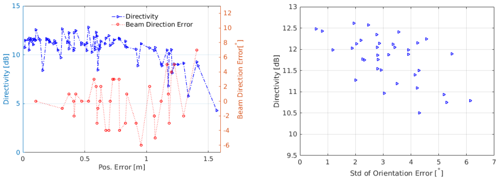
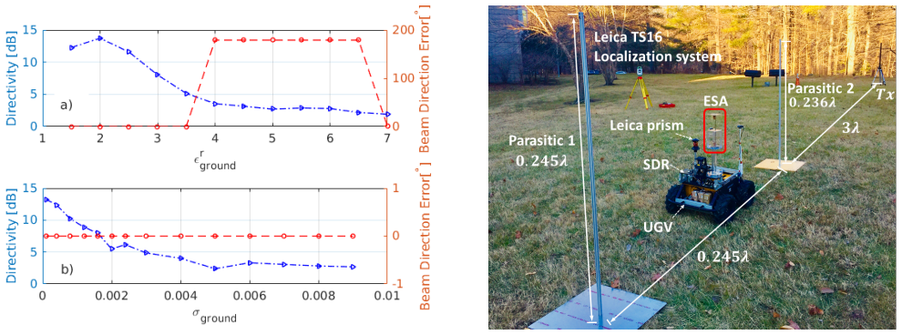
The paper claims that a parasitic Yagi-Uda-style array can be disaggregated across mobile robots and still deliver useful directivity at 40 MHz, where the wavelength is 7.5 m. In simulation, a five-element baseline array with a free-space design keeps a mean directivity of about 11.3 dB and a mean beam-direction error under 1.2 degrees when the reflector position error stays below 60 cm, while director errors are the more sensitive link; orientation errors up to about six degrees cost roughly 2 dB. On ground with elevated permittivity and conductivity, the same free-space design loses its directive gain, but a genetic-algorithm search over element positions and lengths recovers a directional pattern with spacings of $0.16\lambda$ for the director and $0.14\lambda$ for the reflector, considerably tighter than the free-space values. An outdoor three-element experiment with one robot carrying an electrically small antenna and two static shorted monopoles produced a mean relative gain of 3.2 dB over the single antenna, which the paper reads as confirmation that mobile parasitic elements can provide directional low-frequency communication that tolerates robotic pose error.
Load-bearing premise
The load-bearing premise is that a homogeneous lossy-dielectric ground slab plus fixed conductive robot bodies models the real outdoor scattering environment well enough for the optimized spacings and the stated pose-error margins to transfer to deployments on actual ground.
Editorial extensions
If this is right
- A multi-robot parasitic array needs only one driven element, so no phase synchronization or shared clock among agents is required; steering is done by moving passive elements.
- At 40 MHz, position errors up to about $0.07\lambda$ (roughly 50 cm) in the directors and 60 cm in the reflector keep directivity near 11 dB and pointing error near 1.2 degrees, within what current robot pose estimation can provide.
- Ground electromagnetic properties are first-order design variables: the free-space Yagi configuration degrades sharply on high-permittivity, lossy ground, and re-optimization (director at $0.16\lambda$, reflector at $0.14\lambda$) restores a directional beam.
- The measured 3.2 dB gain over a single electrically small antenna in an outdoor test indicates the concept works outside simulation, albeit below the 6.5 dB a three-element free-space design would give.
- Because the tolerance scales with wavelength, the same fixed position error is a smaller fraction of a wavelength at 40 MHz than at higher VHF, so lower frequencies are more forgiving of robotic positioning error.
Reading between the lines
- If the tolerance scales linearly with wavelength, the 60 cm reflector margin at 40 MHz shrinks to about 24 cm at 100 MHz, so the robotic pose requirements tighten as frequency rises; the paper notes the trend but does not quantify it.
- The ground-aware optimization suggests a practical pre-deployment step the paper leaves implicit: nodes could estimate local soil permittivity and conductivity and then reposition their parasitic elements to the corresponding optimized spacings, rather than treating the array geometry as fixed.
- A 3.2 dB measured gain corresponds to roughly a factor of two in received power, which in a free-space-like link would extend range by about 40 percent or allow a similarly lower transmit power for the same range; this follows from the reported gain rather than being stated by the authors.
- The single-exciter architecture could be extended to multiple driven elements for multi-beam or MIMO-like operation, a direction the paper mentions as future work.
Signed reviews
Editorial analysis
A structured set of objections, weighed in public.
Referee Report
Summary. The paper proposes a distributed parasitic antenna array for low-VHF (40 MHz) directional communication among ground robots. Section II reviews the two-element parasitic array gain formula (Eq. (1)) from textbook theory. Section III presents full-wave FDTD simulations with UGV body models and a homogeneous lossy ground, studying how reflector position error, director position error, and orientation error affect directivity and beam direction. Section IV describes an outdoor experiment in which a robot carrying a λ/25 electrically small antenna (ESA) is moved between two shorted aluminum monopole parasitics, with 'relative gain' computed as the received-power difference with and without the parasitics; the paper reports a mean gain of 3.2 dB. Section V uses a genetic algorithm coupled to the FDTD solver to optimize parasitic element spacing and length for a concrete ground, yielding a director spacing of 0.16λ and a reflector spacing of 0.14λ. The abstract concludes that the results 'demonstrate the ability to achieve directional low frequency communications that is robust to robotic pose error.'
Significance. If fully substantiated, the paper would offer a practically relevant concept: a parasitic array with a single driven element and robot-mobile passive elements avoids the synchronization and high-accuracy positioning demands of conventional distributed phased arrays, while leveraging low-VHF propagation for obstacle penetration. The use of full-wave FDTD with integrated UGV models and the hybrid GA optimization over ground dielectric properties are strengths, and the paper is appropriately framed as a first step. However, the central quantitative claims are not yet supported as stated: the headline directivity and robustness numbers come from simulations that are never compared with measurement, and the outdoor experiment does not isolate directional array gain from impedance, pattern, or multipath effects. The paper would be substantially strengthened by reporting sample sizes and error bars, adding an impedance/pattern calibration to the experiment, and tempering the abstract's claim to match the evidence.
major comments (4)
- [Section IV, Fig. 8] The 'relative gain' reported in Section IV is a raw difference in received power measured with and without the two shorted parasitic elements. Because the driven element is an electrically small λ/25 antenna whose input impedance is dominated by reactance, mutual coupling from the nearby parasitics can change the input impedance and therefore the received power independently of any change in radiation pattern. No S11 or impedance-matching calibration is reported in either condition, no radiation pattern, front-to-back ratio, or beam direction is measured (the transmitter sits at one fixed angle), and no repeat counts, standard deviations, or multipath checks are provided. The mean 3.2 dB therefore cannot be attributed specifically to directional array gain, and the abstract's claim that the results 'demonstrate the ability to achieve directional low frequency communications' is stronger than the evidence supports.
- [Section III-B vs. Section IV] The headline simulation results (11.3 dB mean directivity and 1.2° mean beam error for reflector errors under 60 cm, plus the GA-optimized 0.16λ/0.14λ spacings in Section V) are never benchmarked against measurement. The experimental array in Section IV is a different 3-element configuration with a λ/25 ESA driven element and shorted monopole parasitics, whereas the robustness study in Section III-B uses a 5-element array with a different driven element and parasitics. Without a measured gain pattern or directivity comparison on the simulated geometry, the robustness claim in the abstract rests solely on FDTD simulation and does not follow from the outdoor experiment.
- [Section III-B, Figures 3-5] Figures 3-5 plot one FDTD realization per data point and report 'mean' values without sample sizes, standard deviations, or confidence intervals. For example, the statement that errors smaller than 60 cm 'result in a mean directivity of 11.3 dB and a mean beam direction error of 1.2°' has no statistical support as reported; a reader cannot assess whether differences between reflector-error and director-error cases are significant. The paper should state the number of realizations per point, the spread of results, and the distribution assumptions used.
- [Section III-A and Section V] The ground is modeled throughout as a homogeneous lossy dielectric slab (Table I) with fixed UGV bodies, and the Section V optimization is performed for a single concrete ground (εr=4.5, σ=0.01). The paper does not address how heterogeneous, layered, or time-varying ground, or detailed robot scattering, would affect the optimized spacings and the stated robustness margins. This limits the generality of the conclusion that the approach is robust to robotic pose error in real deployment environments; at minimum the abstract and conclusion should present this as a modeling assumption rather than a demonstrated field property.
minor comments (4)
- [Table I] The table contains spelling errors ('uncertainity') and a likely inconsistency: both tw and tg are listed as 'Diameter of all elements' with different values, so one entry presumably refers to a different physical dimension (perhaps the UGV body) and should be clarified.
- [Section V, Eqs. (5)-(7)] The tolerance parameters ϵg, ϵz, and ϵl in the GA objective functions are never assigned numerical values, so the convergence criteria and the sensitivity of the optimized spacing/length results to these tolerances cannot be assessed.
- [Section IV] The experiment reports a single mean gain of 3.2 dB without specifying the number of trials per configuration, the spread across trials, or any check for channel stability; adding per-configuration statistics would make the result interpretable.
- [Section VI] There is a typo in the conclusion ('a accurately determine'), and the conclusion's claim that the simulation results were 'tested with an outdoor experiment' overstates what was tested, since the experiment does not use the simulated array geometry.
Circularity Check
No significant circularity: the simulations, optimization, and experiment are self-contained and not definitionally forced.
full rationale
The paper's main results are obtained by three independent routes: (i) full-wave FDTD simulations that solve Maxwell's equations for randomized element positions and orientations (Section III), (ii) an outdoor measurement that directly compares received power with and without two shorted parasitic elements (Section IV), and (iii) a genetic-algorithm search over element spacings and lengths using FDTD fitness evaluations (Section V). None of these is equivalent, by construction, to the claimed outcome. Equation (1) is a textbook two-element parasitic-array gain expression attributed to ref. [11]; it is used only to motivate the design, and the paper explicitly says multi-element patterns are obtained numerically. The GA-optimized spacings (0.16 lambda director, 0.14 lambda reflector) are presented as the output of an optimization subject to constraints (5)-(7), not as an independent prediction, so showing that the optimized pattern meets those constraints is a design check, not a circular validation. The experiment defines relative gain as received power with parasitics minus received power without; reporting a 3.2 dB mean is a direct measurement, and although the paper does not calibrate impedance or multipath, that is a correctness/measurement-quality concern, not a circularity. The self-citations [1], [2] support background claims about electrically small antennas and are not load-bearing for the directional-array derivation. No circular step is present.
Assumptions & free parameters
free parameters (7)
- GA-optimized director spacing =
0.16 lambda (48.4% reduction from free space)
- GA-optimized reflector spacing =
0.14 lambda (44% reduction from free space)
- GA-optimized director length =
8.8% shorter than baseline director length
- GA-optimized reflector length =
0.3% longer than baseline reflector length
- Position uncertainty bound for simulated errors =
+/-0.2 lambda (up to 1.5 m)
- Orientation uncertainty bound for simulated errors =
+/-10 degrees
- GA convergence tolerances =
not reported
assumptions (5)
- domain assumption A commercial FDTD solver solves Maxwell's equations accurately for the modeled geometry.
- domain assumption The ground can be represented as a homogeneous lossy dielectric with parameters from Table I.
- domain assumption The free-space Yagi-Uda baseline from [11] is a valid starting point and comparison reference.
- domain assumption Uniformly distributed errors over the chosen ranges capture realistic robot pose error.
- domain assumption Received-power difference with and without parasitics equals array gain.
Cite this review
Pith. "Pith review of Directional Communication Enabled by Mobile Parasitic Elements." pith.science (2026). https://pith.science/paper/CZLUNGOX
@misc{pith2026190806816,
  author       = {Pith},
  title        = {Pith review of: Directional Communication Enabled by Mobile Parasitic Elements},
  year         = {2026},
  howpublished = {\url{https://pith.science/paper/CZLUNGOX}},
  note         = {Machine review of arXiv:1908.06816}
}
read the original abstract
Mobile communications in complex environments such as mega-cities is a challenging problem that limits the ability to deploy autonomous agents in support of operations. Building on recent progress in low frequency networking that utilizes miniature antennas to provide persistent connectivity among agents, we consider the design and collaborative manipulation of a distributed robotic antenna array to provide directional communications that will enable enhanced networking, interference rejection, and collaborative control. The use of parasitic elements in a Yagi-Uda type array design avoids the need for synchronization and highly accurate position control among the agents. We utilize physics-based simulations to investigate the feasibility of using mobile agents equipped with an excited antenna element along with a set of support nodes having parasitic elements that adaptively configure to enhance radiation in a desired direction. We take into account mobile node pose uncertainty including element position and angular orientation, as well as ground scattering effects. We pursue an optimal design approach for different types of ground electromagnetic characteristics based on a hybrid full-wave propagation simulation and genetic algorithm optimization. We also present experiment with one mobile node and two static elements. The results demonstrate the ability to achieve directional low frequency communications that is robust to robotic pose error.
Figures


Figures from the paper (3 more)


Reference graph
Works this paper leans on
-
[1]
Electrically small folded dipole antenna for hf and low-vhf bands,
J. Choi, F. T. Dagefu, B. M. Sadler, and K. Sarabandi, “Electrically small folded dipole antenna for hf and low-vhf bands,” IEEE Antennas and Wireless Propagation Letters , vol. 15, pp. 718–721, 2016
work page 2016
-
[2]
Extremely small two- element monopole antenna for hf band applications,
J. Oh, J. Choi, F. T. Dagefu, and K. Sarabandi, “Extremely small two- element monopole antenna for hf band applications,” Antennas and Propagation, IEEE Transactions on, vol. 61, no. 6, pp. 2991–2999, 2013
work page 2013
-
[3]
The virtual linkage: A model for internal forces in multi-grasp manipulation,
D. Williams and O. Khatib, “The virtual linkage: A model for internal forces in multi-grasp manipulation,” in Robotics and Automation, 1993. Proceedings., 1993 IEEE International Conference on . IEEE, 1993, pp. 1025–1030
work page 1993
-
[4]
A potential field based approach to multi- robot manipulation,
P. Song and V . Kumar, “A potential field based approach to multi- robot manipulation,” in Robotics and Automation, 2002. Proceedings. ICRA’02. IEEE International Conference on , vol. 2. IEEE, 2002, pp. 1217–1222
work page 2002
-
[5]
Cooperative localization and control for multi-robot manip- ulation,
J. Spletzer, A. K. Das, R. Fierro, C. J. Taylor, V . Kumar, and J. P. Ostrowski, “Cooperative localization and control for multi-robot manip- ulation,” in Intelligent Robots and Systems, 2001. Proceedings. 2001 IEEE/RSJ International Conference on , vol. 2. IEEE, 2001, pp. 631– 636
work page 2001
-
[6]
Human-robot collaborative manipulation planning using early prediction of human motion,
J. Mainprice and D. Berenson, “Human-robot collaborative manipulation planning using early prediction of human motion,” in Intelligent Robots and Systems (IROS), 2013 IEEE/RSJ International Conference on . IEEE, 2013, pp. 299–306
work page 2013
-
[7]
Robust control of mobility and communications in autonomous robot teams,
J. Fink, A. Ribeiro, and V . Kumar, “Robust control of mobility and communications in autonomous robot teams,” IEEE Access , vol. 1, pp. 290–309, 2013
work page 2013
-
[8]
A note on the mutual-coupling problems in transmitting and receiving antenna arrays,
H.-S. Lui, H. T. Hui, and M. S. Leong, “A note on the mutual-coupling problems in transmitting and receiving antenna arrays,” IEEE Antennas & Propagation Magazine , vol. 51, no. 5, pp. 171–176, 2009
work page 2009
Show all 19 references
-
[9]
Mutual coupling com- pensation in ucas: Simulations and experiment,
Z. Huang, C. A. Balanis, and C. R. Birtcher, “Mutual coupling com- pensation in ucas: Simulations and experiment,” IEEE Transactions on Antennas and Propagation , vol. 54, no. 11, pp. 3082–3086, 2006
2006
-
[10]
Adaptive beamforming for uniform linear arrays with unknown mutual coupling,
B. Liao and S.-C. Chan, “Adaptive beamforming for uniform linear arrays with unknown mutual coupling,” IEEE Antennas and Wireless Propagation Letters, vol. 11, pp. 464–467, 2012
2012
-
[11]
J. D. Kraus, R. J. Marhefka, and A. S. Khan, Antennas for all applications. McGraw-Hill, 2002
2002
-
[12]
Wireless node localization based on rssi using a rotating antenna on a mobile robot,
J. Graefenstein, A. Albert, P. Biber, and A. Schilling, “Wireless node localization based on rssi using a rotating antenna on a mobile robot,” in Positioning, Navigation and Communication, 2009. WPNC 2009. 6th Workshop on. IEEE, 2009, pp. 253–259
2009
-
[13]
Online localization of radio-tagged wildlife with an autonomous aerial robot system
O. M. Cliff, R. Fitch, S. Sukkarieh, D. Saunders, and R. Heinsohn, “Online localization of radio-tagged wildlife with an autonomous aerial robot system.” in Robotics: Science and Systems , 2015
2015
-
[14]
A pattern reconfigurable microstrip parasitic array,
S. Zhang, G. Huff, J. Feng, and J. Bernhard, “A pattern reconfigurable microstrip parasitic array,” IEEE Transactions on Antennas and Propa- gation, vol. 52, no. 10, pp. 2773–2776, 2004
2004
-
[15]
Mems-switched parasitic- antenna array for radiation pattern diversity,
L. Petit, L. Dussopt, and J.-M. Laheurte, “Mems-switched parasitic- antenna array for radiation pattern diversity,” IEEE Transactions on Antennas and Propagation , vol. 54, no. 9, pp. 2624–2631, 2006
2006
-
[16]
Analysis of yagi-uda-type antennas,
G. Thiele, “Analysis of yagi-uda-type antennas,” IEEE Transactions on Antennas and Propagation , vol. 17, no. 1, pp. 24–31, 1969
1969
-
[17]
Design of yagi-uda antennas using genetic algorithms,
E. A. Jones and W. T. Joines, “Design of yagi-uda antennas using genetic algorithms,” IEEE Transactions on Antennas and Propagation , vol. 45, no. 9, pp. 1386–1392, 1997
1997
-
[18]
[Online]
Emag technologies inc. [Online]. Available: https://www.emagtech.com
-
[19]
(2019) Leica viva ts16 - worlds first self-learning total station
Leica. (2019) Leica viva ts16 - worlds first self-learning total station. [Online]. Available: https://leica-geosystems.com/en-US/ products/total-stations/robotic-total-stations/leica-viva-ts16
2019
Reviewed August 14, 2026 · model on record in the stance chip above.
Discussion (0). Continue with ORCID to comment.