REVIEW 2 major objections 5 minor 25 references
Design, Assembly, Calibration, and Measurement of an Augmented Reality Haploscope
T0 review · 2 major / 5 minor · reviewed 2026-08-14 · deepseek-v4-flash
Pith's one-line read A five-step calibration procedure aligns an AR haploscope's optics with the viewer's eye.
desk verdict A rare, detailed haploscope calibration write-up that contains a genuine geometric error in its vergence-angle formula—fixable, but the paper as written would misdirect anyone who follows Eq. 1. read the letter →
The pith
A machine-rendered reading of the paper's core claim, the machinery that carries it, and where it could break.
The reading
What carries the argument
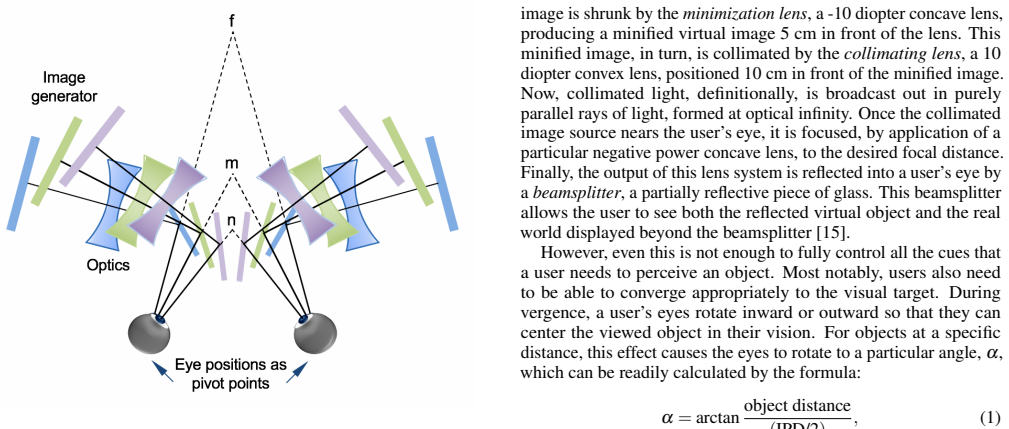
The argument is carried by a three-stage optical chain and a laser-defined calibration coordinate system. The monitor image passes through a $-10$ diopter minimization lens that creates a minified virtual image $5$ cm in front of the lens; a $+10$ diopter collimating lens placed $10$ cm away turns that image into collimated light, and an accommodation lens of adjustable negative power refocuses it to a chosen focal distance before a beamsplitter reflects it into the user's eye, while lens positions follow the thin-lens equation $\frac{1}{f} = \frac{1}{u} + \frac{1}{v}$. The vergence angle is set by $\alpha = \arctan\left(\frac{\text{object distance}}{\mathrm{IPD}/2}\right)$, and the wings rotate about the modeled eye position so the system's optical axes stay collinear with the user's. The load-bearing model is the schematic eye — a center of rotation, a single nodal point, and a pupil, all on one line — and the ground truth of the whole calibration is the gravity-balanced laser level, which defines a coordinate plane through which each rail's optical axis, each beamsplitter's reflected ray, and the user's modeled axis are brought into coincidence.
What would settle it
A direct test: place a camera with its entrance pupil at the modeled nodal point and photograph a calibration target through each wing while rotating the wings across the full vergence range. If the target's image position or focus changes with rotation angle, or equivalently if the binocular parallax of the target shifts as the wings turn, then the claim that every point on the user's optical axis receives the same stimulus regardless of rotation fails at that rotation.
Extended reading notes
Core claim
On the paper's own terms, the discovery is procedural: an AR haploscope assembled from off-the-shelf optics can be calibrated so that its optical axes remain collinear with a user's modeled optical axis across the full range of vergence rotation. The calibration has five discrete steps: level the table and establish a laser-defined coordinate plane; center every optical element on its rail's axis; collimate the monitor image and verify it with a dioptometer; adjust each beamsplitter so the reflected ray passes through the wing's pivot point; and set the interpupillary distance using two laser levels and a calibration target, a step that also re-verifies every earlier alignment. The authors claim primacy for the level of descriptive detail: after 180 years of haploscope use since the original stereoscope was reported in 1838, they have not previously found a paper describing these calibration specifics. The paper itself notes, in its future-work section, that refraction, tracking errors, optical distortions, and measurement errors still bound the accuracy of the final calibrated system.
Load-bearing premise
The load-bearing premise is the schematic-eye model: the calibration assumes a human eye behaves as if its center of rotation, a single nodal point, and a pupil all lie on one straight line, so if real eyes rotate about a moving center or have more complex optics, every aligned axis in the device inherits the mismatch.
Editorial extensions
If this is right
- With this recipe, a research group can reproduce a calibrated AR haploscope from off-the-shelf parts without rediscovering the alignment steps.
- Perceptual AR experiments that need independent control of focal demand and vergence angle, such as depth matching or accommodation-vergence studies, become repeatable procedures.
- The final IPD verification doubles as a check on all earlier calibration steps, because two laser levels must simultaneously bisect the calibration target, each rail's centerline, and each wing's center of rotation.
- Because the wings rotate about the modeled eye position, vergence angle can be changed without introducing the optical distortion that a fixed-axis display would produce.
Reading between the lines
- Because the recipe is written against generic hardware concepts rather than proprietary parts, it plausibly transfers to other optical see-through displays with rotating optical paths, though the paper does not demonstrate such a transfer.
- The schematic-eye premise sets an implicit boundary on the claim: real eyes have a slightly moving rotation center and more complex optics, so the 'same stimulus at every rotation' invariance should degrade at extreme vergence angles, and measuring that degradation would map the model's limits.
- The paper's own list of residual error sources suggests a natural follow-on: quantifying refraction, distortion, tracking, and measurement errors would turn the recipe into a metrology with error bars, letting laboratories compare calibration quality across devices.
Signed reviews
Editorial analysis
A structured set of objections, weighed in public.
Referee Report
Summary. This paper describes the design, assembly, and calibration of an augmented reality haploscope, an optical bench device that presents virtual images at controlled accommodative and vergence distances while allowing the user to see the real world. The authors claim to provide the first systematic, published account of such calibration procedures. The central geometric claim is stated in Section 3: because each haploscope wing rotates about a point coincident with the modeled center of rotation of the user's eye, the optical axis of each wing remains collinear with the user's optical axis for any rotation angle, so that 'each point on the user's optical axes, including the nodal point, is presented with the same optical stimuli, regardless of rotation.' The calibration procedure consists of five steps: leveling the table and establishing a laser-based coordinate plane; centering optical elements and monitors on the rail axes; collimating the monitor image using the thin lens equation and verifying with a dioptometer; adjusting the beamsplitters so that the reflected optical axis passes through the pivot point; and adjusting and verifying the interpupillary distance (IPD) for each user. The paper is written as a procedural manual and includes photographs, a ray diagram, and references to prior theses and publications from the authors' laboratory.
Significance. If correct, the paper would provide a detailed, reproducible recipe for a laboratory instrument that can precisely control stereoscopic presentation parameters, which is valuable for research on depth perception, accommodation-vergence mismatch, and AR perception generally. The authors are honest about the scope: they describe an existing device and its calibration, not new perceptual results. The procedural detail is substantial, and the use of standard optical tools (laser level, dioptometer, thin lens equation) grounds the method in established practice. However, the significance depends entirely on the correctness of the geometric relationship between the rotation angle of the haploscope wings and the user's convergence. As described below, that relationship is stated incorrectly in Eq. (1), and this error is load-bearing for the central invariant claimed in Section 3. In addition, the paper contains no quantitative validation of the claimed alignment accuracy, despite the word 'Measurement' in the title. With the geometric error corrected and the validation gap addressed, the paper could be a useful methods reference.
major comments (2)
- [Section 3, Eq. (1)] Equation (1) defines alpha = arctan(object distance / (IPD/2)), which is the angle between the line of sight and the interocular baseline, not the inward rotation angle of the eye (or haploscope wing) needed to fixate a target at a given distance. For a target at distance d, the required half-convergence angle is theta = arctan((IPD/2)/d). For example, with d = 1 m and IPD = 0.065 m, the printed formula gives approximately 88.1 degrees, while the correct inward rotation is approximately 1.9 degrees. Following the printed procedure would rotate each wing nearly parallel to the baseline, directing the optical axes far to the side rather than at the intended fixation point. This inverts the geometric relationship and, as written, breaks the central claim that the wing axes remain collinear with the user's optical axes. The formula must be corrected and the surrounding text (including the description of alpha as 'the vergence angle or angle of binocular parallax') clarified to state whether alpha is the half-angle or the total angle between the two lines of sight.
- [Section 3 and Section 5] The central invariant stated in Section 3—'each point on the user's optical axes, including the nodal point, is presented with the same optical stimuli, regardless of rotation'—is asserted without any quantitative verification. The paper's title promises 'Measurement,' but no measurement of alignment accuracy, residual angular error, or verification of optical axis coincidence is reported. Section 5 itself concedes that 'refraction, tracking errors, optical distortions, and measurement errors could all potentially be detrimental to the accuracy of the final calibrated haploscope.' Since the paper's contribution is a calibration procedure intended to guarantee a precise geometric relationship, the absence of any validation data (e.g., laser-alignment measurements at multiple rotation angles, or an error budget) leaves the central claim unsupported. At minimum, the authors should either provide such validation or explicitly frame the paper as a methods description whose verification is future work, and adjust the title and abstract accordingly.
minor comments (5)
- [Abstract and Section 6] The abstract and conclusions state that the paper describes 'measurement' of the haploscope, but Section 5 (Future Work) is the only place where measurement errors are discussed; there is no measurement section or reported measurement data. The scope should be stated consistently.
- [Section 3, optical path description] The description of the optical path (e.g., 'a -10 diopter concave lens, producing a minified virtual image 5 cm in front of the lens') would be clearer if the sign conventions for object and image distances in the thin lens equation were defined explicitly, since these distances are central to the collimation step in Section 4.3.
- [Section 4.3] The collimation step relies on the thin lens equation but does not state the actual distances used or the method for positioning the lenses (e.g., whether they are set to the back focal distances of the respective lenses). Without these values or a reference to a specific figure or table, the reader cannot reproduce this step without consulting the cited thesis [10].
- [References [14] and [15]] References [14] and [15] appear to describe the same paper (same title, same authors, same journal) with different citation details; this duplication should be resolved.
- [Section 4.2] The phrase 'shining straight down the center of the rail' is ambiguous; 'straight along the center of the rail' would be clearer.
Circularity Check
No significant circularity: the calibration procedure is anchored to external optical laws and measurement tools, not to the paper's own conclusions.
full rationale
The paper's derivation chain is self-contained and anchored to external optical physics and measurement procedures rather than to its own conclusions. The collimation step uses the standard thin-lens equation (Eq. 2) and verifies collimation with a dioptometer; the beamsplitter and IPD calibration steps use a laser-level coordinate frame, alignment targets, and the geometric requirement that reflected rays pass through the component pivot points; and the vergence angle formula (Eq. 1) is a trigonometric relation between the user's interpupillary distance and object distance. The key structural assumption, that the eye can be modeled as a co-linear center of rotation, nodal point, and pupil, is attributed to external prior work [7, 20], and the device's provenance is traced to Singh's prior haploscope [13, 15] as a matter of design history, not as a proof of correctness. No parameter is fitted and then renamed as a prediction, no result is defined in terms of the claim it supports, and the paper's self-citations describe previous experimental use and calibration details rather than supplying the load-bearing justification. The strongest claim, that the optical axes remain aligned with the user's axes under rotation, follows geometrically from aligning both centers of rotation and is not an empirical prediction that could be circular. The only potentially serious issue in the manuscript, a possible inversion in the printed vergence-angle ratio, would be a geometric correctness error, not a circularity; it does not make the procedure equivalent to its inputs.
Assumptions & free parameters
assumptions (3)
- domain assumption The human eye can be modeled as a schematic eye with center of rotation, single nodal point, and pupil all co-linear.
- domain assumption A gravity-balanced laser level provides a sufficiently accurate coordinate reference for aligning optical components.
- standard math Thin lens equation 1/f = 1/u + 1/v
Cite this review
Pith. "Pith review of Design, Assembly, Calibration, and Measurement of an Augmented Reality Haploscope." pith.science (2026). https://pith.science/paper/QT75SM4D
@misc{pith2026190808532,
  author       = {Pith},
  title        = {Pith review of: Design, Assembly, Calibration, and Measurement of an Augmented Reality Haploscope},
  year         = {2026},
  howpublished = {\url{https://pith.science/paper/QT75SM4D}},
  note         = {Machine review of arXiv:1908.08532}
}
read the original abstract
A haploscope is an optical system which produces a carefully controlled virtual image. Since the development of Wheatstone's original stereoscope in 1838, haploscopes have been used to measure perceptual properties of human stereoscopic vision. This paper presents an augmented reality (AR) haploscope, which allows the viewing of virtual objects superimposed against the real world. Our lab has used generations of this device to make a careful series of perceptual measurements of AR phenomena, which have been described in publications over the previous 8 years. This paper systematically describes the design, assembly, calibration, and measurement of our AR haploscope. These methods have been developed and improved in our lab over the past 10 years. Despite the fact that 180 years have elapsed since the original report of Wheatstone's stereoscope, we have not previously found a paper that describes these kinds of details.
Figures


Figures from the paper (2 more)


Reference graph
Works this paper leans on
-
[1]
M. Banks. Visual space perception laboratory. http://bankslab. berkeley.edu/, 2018. Accessed: 2018-07-01
work page 2018
-
[2]
T. Cook, N. Phillips, K. Massey, A. Plopski, C. Sandor, and J. Edward Swan. User preference for sharpview-enhanced virtual text during non-fixated viewing. In 2018 IEEE Conference on Virtual Reality and 3D User Interfaces (VR) , pp. 1–400, March 2018. doi: 10.1109/VR. 2018.8446058
arXiv 2018
-
[3]
T. A. Decker, R. E. Williams, C. L. Kuether, N. D. Logar, and D. Wyman-Cornsweet. The mark iii haploscope. Technical Report NASA-CR-2584, Baylor Univ.; Dept. of Ophthalmology.; Houston, TX, United States, 1975
work page 1975
-
[4]
F. Domini. 3d shape perception lab. http://www.cog.brown.edu/ research/3Dspl/research.html#cues, 2018. Accessed: 2018- 07-01
work page 2018
-
[5]
S. R. Ellis and U. J. Bucher. Distance perception of stereoscopically presented virtual objects optically superimposed on physical objects by a head-mounted see-through display. In Proceedings of the Human Factors and Ergonomics Society Annual Meeting , vol. 38, pp. 1300–
-
[6]
C. Hua. The Effect of an Occluder on the Accuracy of Depth Per- ception in Optical See-Through Augmented Reality. Master’s thesis, Mississippi State University, Starkville, Mississippi, USA, 2014
work page 2014
-
[7]
J. A. Jones, D. Edewaard, R. A. Tyrrell, and L. F. Hodges. A schematic eye for virtual environments. In 2016 IEEE Symposium on 3D User Interfaces (3DUI), pp. 221–230, March 2016. doi: 10.1109/3DUI.2016 .7460055
-
[8]
E. Kruijff, J. E. Swan II, and S. Feiner. Perceptual issues in augmented reality revisited. In Proceedings of the 9th IEEE International Sympo- sium on Mixed and Augmented Reality 2010: Science and Technology, ISMAR 2010, pp. 3 – 12, 11 2010
work page 2010
Show all 25 references
-
[9]
Lee and H
S. Lee and H. Hua. Effects of configuration of optical combiner on near-field depth perception in optical see-through head-mounted displays. IEEE Transactions on Visualization and Computer Graphics , 22(4):1432–1441, 2016
2016
-
[10]
K. Massey. Procedural Calibration of Haploscope Wings to Establish Accurate Focal Vergence Depth. Master’s thesis, Mississippi State University, Starkville, Mississippi, USA, 2018
2018
-
[11]
Rolland, F
J. Rolland, F. Biocca, F. Hamza-Lup, Y . Ha, and R. Martins. Develop- ment of head-mounted projection displays for distributed, collaborative, augmented reality applications. Presence: Teleoperators and Virtual Environments, 14(5):528–549, 2005
2005
-
[12]
Shirer, T
M. Shirer, T. Mainelli, and J. Ubrani. Demand for augmented real- ity/virtual reality headsets expected to rebound in 2018, says IDC. International Data Corporation , 19 March 2018. Retrieved from https://www.idc.com/getdoc.jsp?containerId=prUS43639318
2018
-
[13]
G. Singh. Near-Field Depth Perception in Optical See-Though Aug- mented Reality. PhD thesis, Mississippi State University, Starkville, Mississippi, USA, 2013
2013
-
[14]
Singh, S
G. Singh, S. R. Ellis, and J. E. Swan II. The effect of focal distance, age, and brightness on near-field augmented reality depth matching. IEEE Transactions on Visualization and Computer Graphics , pp. 1–1,
-
[15]
Singh, S
G. Singh, S. R. Ellis, and J. E. Swan II. The effect of focal distance, age, and brightness on near-field augmented reality depth matching. IEEE Transactions on Visualization and Computer Graphics , PP, Sep 2018
2018
-
[16]
Singh, J
G. Singh, J. E. Swan II, J. A. Jones, and S. R. Ellis. Depth judgment measures and occluding surfaces in near-field augmented reality. In Proceedings of the 7th Symposium on Applied Perception in Graphics and Visualization, pp. 149–156. ACM, 2010
2010
-
[17]
I. E. Sutherland. A Head-Mounted Three Dimensional Display. In Proceedings of the AFIPS Fall Joint Computer Conference , pp. 757–
-
[18]
J. E. Swan II, G. Singh, and S. R. Ellis. Matching and reaching depth judgments with real and augmented reality targets. IEEE Transactions on Visualization and Computer Graphics , 21(11):1289–1298, 2015. doi: 10.1109/TVCG.2015.2459895
2015
-
[19]
Tassinari, F
H. Tassinari, F. Domini, and C. Caudek. The intrinsic constraint model for stereo-motion integration. Perception, 37(1):79–95, 2008. PMID: 18399249. doi: 10.1068/p5501
2008 doi
-
[20]
Westheimer
G. Westheimer. Specifying and controlling the optical image on the human retina. Progress in Retinal and Eye Research , 2006. doi: 10. 1016/j.preteyeres.2005.05.002
2006
-
[21]
Wheatstone
C. Wheatstone. On Some Remarkable, and Hitherto Unobserved, Phenomena of Binocular Vision. Philosophical Transactions of the Royal Society of London , 128:371–394, 1838
-
[22]
M. I. Williams. Haploscope. Patent US 2890620A, United States Patent Office, 1959
1959
-
[764]
Thompson Books, 1968
1968
-
[1304]
SAGE Publications Sage CA: Los Angeles, CA, 1994
1994
-
[2018]
doi: 10.1109/TVCG.2018.2869729
2018
Reviewed August 14, 2026 · model on record in the stance chip above.
Discussion (0). Continue with ORCID to comment.