REVIEW 3 major objections 5 minor 14 references
Analytic Design of Flat-Wire Inductors for High-Current and Compact DC-DC Converters
T0 review · 3 major / 5 minor · reviewed 2026-08-12 · deepseek-v4-flash
Pith's one-line read This paper claims that high-frequency inductance loss in flat-wire inductors is caused by eddy currents opposing the main flux, representable as frequency-dependent reluctance in a magnetic equivalent circuit.
desk verdict Solid DCR formulas and a genuine prototype, but the headline MEC is a qualitative framework with no closed-form core; still worth refereeing. read the letter →
The pith
A machine-rendered reading of the paper's core claim, the machinery that carries it, and where it could break.
The reading
What carries the argument
The load-bearing object is the coupled magnetic-electric equivalent circuit of Fig. 4(c): eddy currents are represented as opposing magnetomotive forces and then as frequency-dependent series reluctances $R_e(j\omega)$ added to the zero-frequency core reluctance $R_0$, yielding total reluctance $R_t=R_0+R_e$ and terminal inductance $L(j\omega)=L_0/(1+Q(j\omega))$. It connects the field-level eddy-current picture to terminal impedance, explaining why $L$ falls with frequency and how geometry (gap count, $D_{left}$, $D_{right}$, $t_w$) enters the loss balance.
What would settle it
Build a 3D finite-element model of the same 41-turn PQ 40/40 prototype including the end turns, and compare its $L(f)$ and $R_{ac}(f)$ curves from 1 kHz to 200 kHz with the MEC formula $L(j\omega)=L_0/(1+Q(j\omega))$; if no single scalar $Q(j\omega)$ reproduces both the measured inductance drop and the measured AC resistance, the lumped-frequency-dependent-reluctance claim is falsified.
Extended reading notes
Core claim
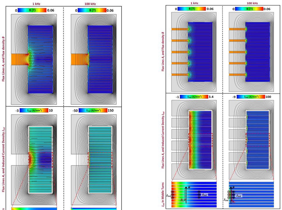
On the paper's own terms, the discovery is that the frequency-dependent behavior of a flat-wire inductor is a flux-rejection effect, not merely a resistive skin effect. The eddy currents stirred up by fringing flux at the distributed gaps and by leakage flux in the window create opposing fields that reduce the flux linked by the coil, so the inductance falls as frequency rises. The authors represent this in a magnetic equivalent circuit by adding frequency-dependent reluctance terms $R_{ef}(j\omega)$ and $R_{elw}(j\omega)$ in series with the zero-frequency reluctance, giving $L(j\omega)=L_0/(1+Q(j\omega))$. They further show that distributed gaps confine fringing flux to smaller conductor volumes and that the gap-to-coil spacing $D_{left}$ is the dominant lever for tuning inductance, because window leakage is rejected by the inner radius of the coil.
Load-bearing premise
The model assumes that all eddy currents circulating in the winding can be represented by one opposing magnetomotive force and one series reluctance whose value is never derived from geometry, so the predicted inductance falloff depends entirely on that simplification.
Editorial extensions
If this is right
- Designers can compute a gap-to-coil spacing $D_{left}$ that minimizes total conduction loss, because larger $D_{left}$ lowers AC loss but raises DCR, and the crossover is explicit.
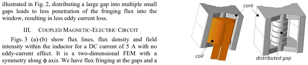
- Distributing a large air gap into several small gaps is directly quantifiable as a reduction in fringing flux penetration into the winding and hence lower eddy-current loss.
- The frequency-dependent inductance $L(j\omega)$ should be used in ripple-current and loss calculations at the converter switching frequency, since the inductance seen by the ripple is not the low-frequency $L_0$.
- Total AC conduction loss for a triangular ripple current can be estimated from the ESR measured at the switching frequency times a constant factor 1.027, avoiding harmonic-by-harmonic FEM.
Reading between the lines
- The paper stops at trends, but the MEC could be inverted to produce a direct design chart that reads off $D_{left}$ and $t_w$ from a target $L$ and $R_{ac}$, turning the sensitivity sweeps into a closed-form sizing procedure.
- Because the residual AC-resistance error (19%) is attributed to leakage in the two end regions without core, a practical refinement would add an end-turn leakage reluctance branch to the MEC before using it for absolute loss prediction.
- The same eddy-current-as-frequency-dependent-reluctance mechanism should transfer to round-wire and foil windings with gap fringing, since it is the reaction flux, not the wire cross-section shape, that drives the inductance falloff.
- A focused experiment that varies only one gap while holding the others fixed could test whether the scalar $Q(j\omega)$ genuinely separates into fringing and window-leakage contributions, which the present lumped fit does not resolve.
Editorial analysis
A structured set of objections, weighed in public.
Referee Report
Summary. The paper presents an analytic study of flat-wire inductors with distributed gaps for compact DC-DC converters, with emphasis on eddy-current losses due to fringing and leakage fluxes. The authors propose a magnetic equivalent circuit (MEC) in which eddy currents are represented by opposing MMFs and frequency-dependent reluctances, leading to a frequency-dependent inductance model. They derive three closed-form DCR formulas, compute AC resistance using vector-potential-based FEM post-processing, and present a sensitivity analysis of design parameters. A prototype is built and tested, showing good agreement for DC resistance (3.3% deviation) and reasonable agreement for inductance and ESR at 100 kHz (5.8% and 19% deviation, respectively).
Significance. If the MEC approach were made fully quantitative, it would offer an interpretable design-oriented explanation of why flat-wire inductor inductance falls with frequency and how eddy currents from fringing and leakage contribute to loss. The DCR formulas are self-contained, parameter-free, and experimentally validated to 3.3%, and the FEM/experimental comparison is a genuine independent check with no fitted constants. The sensitivity study (Fig. 11) provides practical design insight, and the buck-converter validation adds a useful application-level demonstration. However, the central MEC contribution is presently a descriptive framework rather than a predictive analytic model, because the frequency-dependent reluctance is not derived or independently validated.
major comments (3)
- [Section III, Eqs. (1)-(5)] The central claim that eddy currents can be modeled by a frequency-dependent reluctance R_e(jω) in series with the zero-frequency reluctance is only asserted, not derived. No closed-form expression for R_e(jω) in terms of geometry, conductivity, and frequency is provided anywhere in the manuscript. Consequently, Eq. (5), L(jω) = L0/(1+Q(jω)), is an implicit definition of Q(jω) given L(jω), not a prediction. The paper even states that Q(jω) is an 'auxiliary term' with no independent computation. The verification at the level of final inductance and R_ac does not isolate the MEC representation itself. The authors should either derive R_e(jω) from first principles, or explicitly reframe the MEC as a qualitative explanatory framework and move the quantitative burden to the FEM-based calculations.
- [Section V, Eqs. (15)-(23)] The AC resistance calculation is not analytic: Eq. (23) requires the full numerical solution of the vector potential A_φ from FEM, including the eddy-current density J_eddy. The abstract and introduction describe the paper as presenting 'analytic study and design considerations,' but the frequency-dependent loss prediction rests on FEM post-processing. The authors should clarify which parts of the contribution are analytic (the DCR formulas, the harmonic loss summation in Section VII) and which are numerical, and adjust the claims accordingly.
- [Section VII, Fig. 13 and prototype results] The 19% deviation between the measured winding ESR (425 mΩ) and the 2D FEM result (357 mΩ) is attributed to '3D impacts, especially large leakage fluxes in the two conductor regions without a surrounding core.' This is a load-bearing limitation: the 2D model is claimed to verify the design, but a 19% error in the main loss quantity is not negligible for high-current converter design. The paper should either include a 3D FEM comparison, quantify the expected error from 3D effects, or reduce the strength of the claim that the 2D model is experimentally verified.
minor comments (5)
- [General] The manuscript contains numerous typographical errors, including 'EXPETRIMENTAL' (Section VII heading), 'Gausses’ law' (should be 'Gauss’s law' or 'Gauss’ law'), 'cconsidering' (Section IV-C), and 'desomposition' (Section VI heading). A thorough proofreading pass is needed.
- [Equations throughout] Many equations are garbled or incompletely rendered in the provided text (e.g., Eqs. (1), (4), (6), (8), (9), (11), (12), (14), (22), (23), (24)-(30)). The authors should ensure that all equations are typeset correctly and that each symbol is defined where first introduced.
- [Section III, Fig. 4] The MEC diagrams in Fig. 4 are not fully explained in the text: the branch structure and the relation between F_ef, F_ew and the series reluctance R_e(jω) are described qualitatively. A clearer derivation of how two MMF sources are 'shown' to become a single series reluctance is needed, even if only formally.
- [Section VII, Eqs. (24) and (25)] The lumped model in Eq. (24) and the inductance extraction in Eq. (25) are stated without derivation or citation. Please provide a source or a brief derivation for the simplified lumped model and for the ripple-based inductance formula.
- [Section VIII, Conclusion] The final paragraph about physics-informed AI (PIAI) appears unrelated to the rest of the paper and is not supported by any preceding discussion. It should be removed or moved to a separate future-work statement.
Circularity Check
The MEC's frequency-dependent reluctance is a placeholder: Eq. (5) expresses L(jω) through an unspecified Q(jω), so the claimed 'explanation' of inductance fall is definitional rather than predictive; quantitative checks come from FEM and measurement, not from the MEC.
-
self definitional
[Section III, Eq. (5) and the following paragraph]
"It can be seen that the inductance L (jω) is L0 at zero frequency, and at higher frequencies, as Q and subsequently the reluctance goes up, the inductance goes down."
In Eq. (5), Q(jω) is introduced only as R_e(jω)/R_0, and no expression for R_e or Q in terms of frequency, geometry, conductivity, or winding layout is derived anywhere in the paper. Consequently L(jω)=L0/(1+Q(jω)) is an identity: for any measured or simulated L(ω), one may define Q(ω)=L0/L(ω)-1. The statement that inductance falls because Q rises is therefore a restatement of the definition of Q, not a first-principles prediction. The paper's quantitative checks (5.8% L deviation, 19% Rac deviation) compare FEM with measurements, and the MEC's series reluctance is never independently extracted or validated.
full rationale
The paper is largely self-contained on its quantitative side: the DCR formulas in Section IV are derived from geometry, the AC-resistance calculation in Section V starts from the vector-potential form of Maxwell's equations and is implemented in FEM, and the experimental comparisons in Section VII are external checks. No fitted constants are used to force agreement. The main circularity concern is confined to the central MEC claim of Section III: the frequency-dependent reluctance R_e(jω) (or Q(jω)) is a placeholder, and Eq. (5) defines the frequency-dependent inductance through that placeholder. Thus the MEC 'explains' the inductance drop in a way that is analytically equivalent to its own definition unless a separate calculation of R_e is supplied, which the paper does not do. The paper also invokes self-authored prior work [13]-[14] to justify representing eddy currents as frequency-dependent series reluctances; that is a method transfer across devices rather than a fitted result, so it is not itself a circular prediction, but it does add mild self-referential weight to the framework. Overall, the central predictive content of the paper is carried by FEM and measurement, while the MEC is an underdetermined parameterization rather than a closed-form derivation; this warrants a moderate circularity score rather than a clean zero.
Assumptions & free parameters
assumptions (5)
- domain assumption 2D axisymmetric symmetry in the φ direction is sufficient for modeling the inductor
- ad hoc to paper Eddy currents can be represented as MMFs and a frequency-dependent reluctance in series with the zero-frequency reluctance
- standard math Standard Maxwell equations, vector potential, and Coulomb gauge apply
- domain assumption Winding ESR is proportional to sqrt(f) for flat-wire inductors
- domain assumption The litz-wire reference inductor has AC resistance within 10% of its DC resistance at 100 kHz, so its measured ESR equals DCR plus core ESR
invented entities (2)
-
Frequency-dependent reluctance Re(jω)
-
Eddy-current MMF sources Fef and Few
Cite this review
Pith. "Pith review of Analytic Design of Flat-Wire Inductors for High-Current and Compact DC-DC Converters." pith.science (2026). https://pith.science/paper/PB6RN5TM
@misc{pith2026241113307,
  author       = {Pith},
  title        = {Pith review of: Analytic Design of Flat-Wire Inductors for High-Current and Compact DC-DC Converters},
  year         = {2026},
  howpublished = {\url{https://pith.science/paper/PB6RN5TM}},
  note         = {Machine review of arXiv:2411.13307}
}
read the original abstract
This paper presents analytic study and design considerations of flat wire inductors with distributed gaps for high-power and compact DC-DC Converters. The focus is eddy current loss components within the conductors due to fringing and leakage fluxes. A magnetic equivalent circuit (MEC) is proposed in which eddy currents are modeled by MMFs opposing the primary flux as well as frequency dependent reluctances, which finally leads to a frequency dependent inductance describing the behavior of the inductor at high frequencies. Three formulations for DC resistance depending on the required accuracy are developed. Calculations of the AC resistance based on vector potential obtained from FEM are provided. To provide an insight into the optimized design of such inductors, components of the magnetic flux and induced eddy currents along with sensitivity of the main inductor quantities such as DCR, ESR, loss components and inductance values to the design parameters are investigated. Finally, an inductor is prototyped and experimentally tested to verify the design.
Figures


Figures from the paper (8 more)




Reference graph
Works this paper leans on
-
[1]
Next Generation of Power Supplies— Design for Manufacturability,
F. C. Lee, S. Wang and Q. Li, “Next Generation of Power Supplies— Design for Manufacturability,” IEEE Journal of Emerging and Selected Topics in Power Electronics, vol. 9, no. 6, pp. 6462-6475, Dec. 2021
work page 2021
-
[2]
M. Sato, Y. Hattori, M. Ueda, Y. Bu and T. Mizuno, “Improved Performance of a Flat-Wire Coil with Magnetic Composite Material for Wireless Power Transfer,” IEEE Magnetics Letters, vol. 12, pp. 1-5, 2021
work page 2021
-
[3]
AC resistance of planar power inductors and the quasi-distributed gap technique,
Jiankun Hu and C. R. Sullivan, “AC resistance of planar power inductors and the quasi-distributed gap technique,” IEEE Transactions on Power Electronics, vol. 16, no. 4, pp. 558-567, July 2001
work page 2001
-
[4]
Influence of the Distributed Air Gap on the Parameters of an Industrial Inductor,
R. Jez, “Influence of the Distributed Air Gap on the Parameters of an Industrial Inductor,” IEEE Transactions on Magnetics, vol. 53, no. 11, pp. 1-5, Nov. 2017
work page 2017
-
[5]
Procedure to compare different design methods for implementation- ready high power inductors,
C. Kjeldsen, C. Østergaard, M. Nymand and R. Ramachandran, “Procedure to compare different design methods for implementation- ready high power inductors,” 2019 IEEE 13th International Conference on Compatibility, Power Electronics and Power Engineering (CPE- POWERENG), Sonderborg, Denmark, 2019, pp. 1-6
work page 2019
-
[6]
A Novel Power Inductor and Its Application for Compact, Large Current DC-DC Converters,
Y. Zhang, X. Guo, G. Wang and Q. Xiao, “A Novel Power Inductor and Its Application for Compact, Large Current DC-DC Converters,” 2021 IEEE Applied Power Electronics Conference and Exposition (APEC), Phoenix, AZ, USA, 2021, pp. 2865-2869
work page 2021
-
[7]
An Integrated Power Module Based on the Power-System-In-Inductor Structure,
L. Wang, W. Liu, D. Malcom and Y. -F. Liu, “An Integrated Power Module Based on the Power-System-In-Inductor Structure,” IEEE Transactions on Power Electronics, vol. 33, no. 9, pp. 7904-7915, Sept. 2018
work page 2018
-
[8]
Winding Resistance and Power Loss of Inductors with Litz and Solid-Round Wires,
R. P. Wojda and M. K. Kazimierczuk, “Winding Resistance and Power Loss of Inductors with Litz and Solid-Round Wires,” IEEE Transactions on Industry Applications, vol. 54, no. 4, pp. 3548-3557, July-Aug. 2018
work page 2018
Show all 14 references
-
[9]
Analysis and Design of Choke Inductors for Switched-Mode Power Inverters,
D. K. Saini, A. Ayachit, A. Reatti and M. K. Kazimierczuk, “Analysis and Design of Choke Inductors for Switched-Mode Power Inverters,” IEEE Transactions on Industrial Electronics, vol. 65, no. 3, pp. 2234-2244, March 2018
2018
-
[10]
Modeling of High Power Inductors Based on Solid Flat Wires for Compact DC-DC Converters,
A. Namadmalan, “Modeling of High Power Inductors Based on Solid Flat Wires for Compact DC-DC Converters,” 2024 IEEE Kansas Power and Energy Conference (KPEC), Manhattan, KS, USA, 2024, pp. 1-5
2024
-
[11]
Multi-Objective Design of Single-Phase Differential Buck Inverters with Active Power Decoupling,
R. Rajamony, S. Wang, R. Navaratne and W. Ming, “Multi-Objective Design of Single-Phase Differential Buck Inverters with Active Power Decoupling,” IEEE Open Journal of Power Electronics, vol. 3, pp. 105- 114, 2022
2022
-
[12]
Design Optimization of Inductive Power Transfer Systems Considering Bifurcation and Equivalent AC Resistance for Spiral Coils,
A. Namadmalan, B. Jaafari, A. Iqbal and M. Al-Hitmi, “Design Optimization of Inductive Power Transfer Systems Considering Bifurcation and Equivalent AC Resistance for Spiral Coils,” IEEE Access, vol. 8, pp. 141584-141593, 2020
2020
-
[13]
An Actuator with Magnetic Restoration, Part I: Electromechanical Model and Identification,
S. Mohammadi, W. R. Benner, J. L. Kirtley, and J. H. Lang, “An Actuator with Magnetic Restoration, Part I: Electromechanical Model and Identification,” IEEE Transactions on Energy Conversion, 2024, doi:10.1109/TEC.2024.3387390
2024
-
[14]
Modeling, Design, Identification, Drive, and Control of a Rotary Actuator with Magnetic Restoration,
S. Mohammadi, “Modeling, Design, Identification, Drive, and Control of a Rotary Actuator with Magnetic Restoration,” Ph.D dissertation, Department of Electrical Engineering and Computer Science., Massachusetts Institute of Technology, 2022
2022
Reviewed August 12, 2026 · model on record in the stance chip above.
Discussion (0). Continue with ORCID to comment.