REVIEW 2 major objections 4 minor 41 references
Upgrade of the Diagnostic Neutral Beam Injector for the RFX-mod2 experiment
T0 review · 2 major / 4 minor · reviewed 2026-08-12 · deepseek-v4-flash
Pith's one-line read The aged 50 kV acceleration chain of RFX-mod2's diagnostic beam still holds its rated voltage, so the injector can be refurbished in-house.
desk verdict A transparent, useful engineering report on a BINP-built DNBI upgrade; the 50 kV capability claim is only demonstrated at low current, but the paper says so itself and the tests are real. read the letter →
The pith
A machine-rendered reading of the paper's core claim, the machinery that carries it, and where it could break.
The reading
What carries the argument
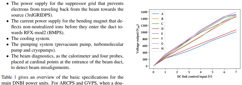
The load-bearing object is the 50 kV generation chain: a 150 mF capacitor bank charged to 830 V, partially discharged through eight DC link-inverter lines whose outputs are stepped up, rectified, filtered, and connected in series to reach 50 kV. Testing this chain on the 55 kΩ second-grid resistive divider is what grounds the central feasibility claim. The other carrying mechanism is the new high-voltage deck powering scheme, in which a single 100 kV insulation transformer feeds a commercial 500 V DC supply that keeps an in-deck capacitor bank charged for the arc power supply, replacing the faulty custom insulation transformer. For the control upgrade, the key component is the ESP32-C3 microcontroller retransmitting the 160 kHz clock to IGBT drivers and adjusting duty cycle between 20 kHz pulses, with the ISO5451 gate driver providing shorter propagation delay and higher insulation voltage.
What would settle it
Connect a load that draws the nominal 5 A at 50 kV, or extract a real 50 ms beam pulse, and check whether the output holds 50 kV with acceptable ripple and modulation. If the voltage sags, trips, or cannot start with inverters A and D at their reduced output, the central feasibility claim is false; identifying why those two inverters deliver about 30% less voltage would also settle how much margin the system really has.
Extended reading notes
Core claim
The paper's central claim is that despite aging electronics and a faulty custom insulation transformer, the DNBI's 50 kV acceleration system remains usable: when the complete chain was tested on the 55 kΩ resistive divider, it reached and held 50 kV for at least 50 ms, even with two of the eight inverters producing about 30% lower output. The authors conclude from this that the acceleration power devices can still generate the rated voltage, which makes the in-house refurbishment feasible. They also report that the redesign is practical: one commercial DC-DC converter survived 130 mT magnetic field pulses while six others failed, so the high-voltage deck will use that converter and shield or relocate vulnerable devices; the custom triple insulation transformer will be replaced by a single 100 kV insulation transformer with the capacitor bank moved inside the deck; IGBT drivers can be modernized with microcontrollers that meet latency, jitter, and insulation requirements; and the CAMAC control system can be replaced by PLC and fast data acquisition devices communicating over two optical fibers.
Load-bearing premise
The whole case rests on assuming the 50 kV chain behaves the same at the rated 5 A beam current as it did in the low-current test on the 55 kΩ divider, which drew only about 0.9 A and used six healthy inverters to compensate for two degraded ones.
Editorial extensions
If this is right
- The 50 kV acceleration chain can be kept in service, avoiding the cost and delay of building a new high-voltage system.
- The faulty custom triple insulation transformer can be replaced by a single 100 kV insulation transformer with the capacitor bank moved inside the high-voltage deck, simplifying the power scheme.
- IGBT control can be rebuilt around a microcontroller and a modern gate driver, meeting the required switching latency, jitter, and insulation specifications.
- The CAMAC control system can be replaced by a PLC plus fiber-linked fast data acquisition without losing timing resolution or analog conversion quality.
- Only one tested DC-DC converter is safe to operate at twice the expected magnetic field, so the others need shielding, relocation, or replacement.
Reading between the lines
- Beyond the paper: if a full 5 A test reveals sag from the two degraded inverter lines, replacing their low-voltage control electronics is the likely fix, since the paper already identifies aged electronics as the suspected cause.
- Beyond the paper: the magnetic-field converter test should be repeated with field transients as fast as an RFX-mod2 shot; the paper notes the available generator could not do this, so the solenoid commissioning phase is the natural place to settle it.
- Beyond the paper: because the paper frames this work as part of a collective effort to keep several injectors of the same design running in Europe, the same refurbishment path likely transfers to other laboratories facing the same loss of manufacturer support.
Editorial analysis
A structured set of objections, weighed in public.
Referee Report
Summary. The paper reports the engineering upgrade of the Diagnostic Neutral Beam Injector (DNBI) for the RFX-mod2 reversed-field-pinch experiment, focusing on the electrical power systems. It describes restoration and tests of the 50 kV acceleration-voltage generation chain, a redesign of the IGBT control using ESP32-C3 microcontrollers and ISO5451 gate drivers, magnetic-field survival tests of candidate commercial DC-DC converters, the new high-voltage-deck powering scheme, and the replacement of the CAMAC control and data acquisition system with a PLC and fast-DAQ architecture. The main experimental results are that the 50 kV chain reached the design voltage for at least 50 ms on a 55 kΩ divider (about 0.9 A instead of the nominal 5-8 A), two of eight inverters show about 30% lower output, one of seven DC-DC converters survives 130 mT static fields, and the new IGBT driver successfully switched 80 A on a bench load. The paper concludes that the acceleration system can still generate 50 kV and that the in-house refurbishment is feasible.
Significance. If the reported results and caveats are properly reflected in the conclusions, the paper is a useful and honest engineering case study for the in-house refurbishment of BINP-built DNBIs in Europe, which is practically important given the unavailability of the original manufacturer. It is based on direct hardware measurements with no fitting or circular reasoning, and it provides data and code for Figure 4 and the ESP32-C3 tests, which is a strength. The main qualification is that the headline 50 kV milestone was demonstrated only at about 0.9 A, not at the rated 5-8 A, so the feasibility conclusion must be either qualified to the tested low-current condition or supported by further full-current tests. With that revision, the paper is a solid contribution to the fusion engineering literature.
major comments (2)
- [Section 3.1 and Conclusions] The full-system 50 kV test was made on the 55 kΩ resistive divider used for the second-grid potential, drawing I = 50 kV / 55 kΩ ≈ 0.9 A. The nominal acceleration load is given as about 5 A in the text, while Table 1 rates the 50 kV system at 8 A; the test therefore covers only about 11-18% of the rated current. This validates the generation chain near open circuit but does not demonstrate load regulation at the actual acceleration current: series impedances in the DC links, inverters, step-up transformers, and rectifiers could produce voltage drops that are invisible in this test. The same applies to the reported 0-100% modulation tests, which were also performed on the divider. The conclusion that the system 'can still generate 50 kV' and that this is 'an important milestone in determining the overall feasibility and convenience of the DNBI refurbishment' is stronger than the evidence; please qualify it to 'at low current' and either add a full-current test on a suitable high-power dummy load or present load-regulation measurements at intermediate currents.
- [Section 3.1 and Figure 4] Two of the eight inverter chains (A and D) deliver about 30% lower output, and the paper states that wiring losses and control-board settings were excluded as causes while the actual cause is not identified ('overall aging' is assumed). This is a load-bearing reliability concern for the full-current claim: at 5-8 A the six healthy chains might have to operate beyond their demonstrated headroom, and the degraded chains could limit the series output or fail under repeated stress. The manuscript should state whether the healthy chains have sufficient margin to compensate at full current, and should present a concrete diagnostic or replacement plan for inverters A and D rather than leaving the cause open.
minor comments (4)
- [Table 1 and Section 3.1] The 50 kV system row in Table 1 lists 8 A, while the text in Sections 1 and 3.1 gives the acceleration current as about 5 A; please reconcile this, since it changes how the 0.9 A divider test should be interpreted (11% vs 18% of rated current).
- [References] Reference [41] is listed only as 'Zenodo (2024)' without a DOI or URL; because the paper's reproducibility relies in part on the data and code at that link, please complete the citation.
- [Abstract and Section 3.3] The DC-DC converter qualification was performed under static or quasi-static fields, and the paper notes that rapidly changing fields could not be tested; the abstract's phrase 'should power the electronic boards in a reliable way' should be qualified to reflect that the pulsed-field test is a pending milestone, as already acknowledged in Section 3.3.
- [Section 4.2] The arc-current power supply is presented as a conceptual design; a brief statement on which of its components (thyristor ignition, notch system, LCR filter) have been bench-tested and which remain to be validated would help the reader separate design from demonstrated hardware.
Circularity Check
No circularity: the paper's conclusions are direct measurements, with acknowledged load-test limitations but no definitional or self-citation loop.
full rationale
This is an engineering and test report rather than a derivation chain, and the central claims are supported by direct measurements of the hardware. The 50 kV capability conclusion comes from a high-voltage test on the 55 kΩ divider, and the paper explicitly discloses the limitation: 'In the unavailability of a resistor to mimic the acceleration system load (50 kV, about 5 A), the high voltage output of the entire system was tested on the resistive divider... The total resistance of the divider amounts to 55 kΩ.' That test draws only about 0.9 A instead of the nominal 5 A, so the conclusion that the system 'can still generate 50 kV' is not demonstrated at full rated current; however, this is a question of test coverage and extrapolation, not circularity. No parameter is fitted to a subset of data and then renamed as a prediction; no equation is defined in terms of the result it is supposed to establish; and no load-bearing premise is imported solely from a self-citation chain. Citations to prior RFX-mod publications, component datasheets, and reference [13] for the original DNBI design are contextual and do not substitute for the tests reported here. The acknowledged limitations, such as the inability to test DC-DC converter 1 under rapidly changing magnetic fields, further confirm that the authors identify residual uncertainties rather than smuggling conclusions into their assumptions. The only concern, namely whether low-current divider behaviour is representative of full-current acceleration operation, is an evidentiary or risk concern and does not amount to circular reasoning. Therefore the appropriate finding is no significant circularity, with score 0.
Assumptions & free parameters
assumptions (3)
- domain assumption Static magnetic field survival at 130 mT is representative of the dynamic field environment during RFX-mod2 shots.
- domain assumption Commercial industrial automation components (PLC, D-tAcq DAQ) will maintain specified performance when referenced to a 50 kV potential and connected via optical fibers.
- domain assumption The eight DC-link/inverter lines can be operated with two degraded units producing 30% lower output without loss of the overall 50 kV capability at full load.
Cite this review
Pith. "Pith review of Upgrade of the Diagnostic Neutral Beam Injector for the RFX-mod2 experiment." pith.science (2026). https://pith.science/paper/3FNENGO2
@misc{pith2026241113373,
  author       = {Pith},
  title        = {Pith review of: Upgrade of the Diagnostic Neutral Beam Injector for the RFX-mod2 experiment},
  year         = {2026},
  howpublished = {\url{https://pith.science/paper/3FNENGO2}},
  note         = {Machine review of arXiv:2411.13373}
}
read the original abstract
Diagnostic Neutral Beam Injectors (DNBI), through the combined use of Charge Exchange Recombination Spectroscopy (CHERS) and Motional Stark effect diagnostics (MSE), are a well-known tool to access important information about magnetically confined plasmas, such as radial profiles of ion temperature, ion flow, impurity content and intensity and direction of the magnetic field. For this purpose, a DNBI was installed and operated in the RFX-mod experiment, which was designed to confine plasma mainly through the Reversed Field Pinch configuration. The DNBI, designed and built by the Budker Institute of Nuclear Physics (BINP), was based on a source of positive hydrogen ions, accelerated to 50 keV and for a maximum ion current of 5 A. The beam could be modulated and the maximum overall duration was 50 ms. With the upgrade of RFX-mod to the present RFX-mod2 machine, the DNBI is being renovated to solve several power units faults and improve the overall reliability of the system. The 50 kV power supply is being improved, as well as the power supplies in the high voltage deck and its insulation transformer. Magnetic field survival tests were performed on the toroidal-core-based DC-DC converters that should power the electronic boards in a reliable way. The control system, originally based on CAMAC technology, was redesigned to be fully replaced. This contribution reviews the technical criticalities emerged in the DNBI check-up and the new solutions adopted to make the DNBI operative and more reliable.
Figures


Figures from the paper (4 more)


Reference graph
Works this paper leans on
-
[1]
P.G. Carolan, B.P. Duval, A.R. Field, S.J. Fielding, N.C. Hawkes, N.J. Peacock et al., Charge-exchange-excited line radiation in a tokamak (ASDEX) with neutral-particle-beam injection, Phys. Rev. A 35 (1987) 3454
work page 1987
-
[2]
R.C. Isler, An overview of charge-exchange spectroscopy as a plasma diagnostic, Plasma Physics and Controlled Fusion 36 (1994) 171
work page 1994
-
[3]
D. Wr ´oblewski, L.K. Huang and H.W. Moos, Scanning polarimeter for measurement of the poloidal magnetic field in a tokamak, Review of Scientific Instruments 59 (1988) 2341
work page 1988
-
[4]
F.M. Levinton, R.J. Fonck, G.M. Gammel, R. Kaita, H.W. Kugel, E.T. Powell et al., Magnetic field pitch-angle measurments in the PBX-M tokamak using the motional stark effect, Phys. Rev. Lett. 63 (1989) 2060
work page 1989
-
[5]
B.C. Stratton, D. Long, R. Palladino and N.C. Hawkes, Instrumentation for the joint European torus motional Stark effect diagnostic, Review of Scientific Instruments 70 (1999) 898
work page 1999
-
[6]
R. Wolf, A. Bock, O. Ford, R. Reimer, A. Burckhart, A. Dinklage et al., Motional Stark Effect measurements of the local magnetic field in high temperature fusion plasmas, Journal of Instrumentation 10 (2015) P10008
work page 2015
-
[7]
L. Carraro, M.E. Puiatti, F. Sattin, P. Scarin and M. Valisa, Requirements for an active spectroscopy diagnostic with neutral beams on the RFX reversed field pinch, Review of Scientific Instruments 70 (1999) 861
work page 1999
-
[8]
M. Kuldkepp, M.J. Walsh, P.G. Carolan, N.J. Conway, N.C. Hawkes, J. McCone et al., Motional Stark effect diagnostic pilot experiment for MAST, Review of Scientific Instruments 77 (2006) 10E905
work page 2006
Show all 41 references
-
[9]
J. Ko, D.J. Den Hartog, K.J. Caspary, E.A. Den Hartog, N.A. Pablant and H.P. Summers, Two-point motional Stark effect diagnostic for Madison Symmetric Torus), Review of Scientific Instruments 81 (2010) 10D702
2010
-
[10]
Hartog, J
D.D. Hartog, J. Ambuel, M. Borchardt, K. Caspary, E.D. Hartog, A. Falkowski et al., Advances in time-resolved measurement of magnetic field and electron temperature in low-magnetic-field plasmas, Fusion Science and Technology 59 (2011) 124
2011
-
[11]
Bonomo, D
F. Bonomo, D. Bonfiglio, P. Piovesan, L. Piron, B. Zaniol, S. Cappello et al., Flow measurements and modelling in helical RFX-mod equilibria, Nuclear Fusion 51 (2011) 123007
2011
-
[12]
Zuin, S.D
M. Zuin, S.D. Bello, L. Marrelli, M. Puiatti, P. Agostinetti, M. Agostini et al., Overview of the RFX-mod fusion science activity, Nuclear Fusion 57 (2017) 102012
2017
-
[13]
Korepanov, G.F
S.A. Korepanov, G.F. Abdrashitov, D. Beals, V .I. Davydenko, P.P. Deichuli, R. Granetz et al.,Neutral beam injector for active plasma spectroscopy, Review of Scientific Instruments 75 (2004) 1829
2004
-
[14]
Marrelli, R
L. Marrelli, R. Cavazzana, D. Bonfiglio, M. Gobbin, G. Marchiori, S. Peruzzo et al., Upgrades of the RFX-mod reversed field pinch and expected scenario improvements, Nuclear Fusion 59 (2019) 076027
2019
-
[15]
Peruzzo, D
S. Peruzzo, D. Aprile, M. Dalla Palma, M. Pavei, D. Rizzetto, A. Rizzolo et al., The new vessel complex for the RFX-mod2 experiment: An effective synergy between fusion research and technological development, Fusion Engineering and Design 194 (2023) 113890
2023
-
[16]
Terranova, M
D. Terranova, M. Agostini, F. Auriemma, M. Gobbin, G. Marchiori, L. Pigatto et al., RFX-mod2 as a flexible device for reversed-field-pinch and low-field tokamak research, Nuclear Fusion 64 (2024) 076003
2024
-
[17]
Horelick and R.S
D. Horelick and R.S. Larsen, CAMAC: a modular standard, IEEE Spectrum 13 (1976) 50
1976
-
[18]
J. Wood, B. Lomanowski, E. Delabie, H. Willett, M. Sertoli and J. Varje, Characterisation of ion temperature and toroidal rotation on the ST40 tokamak, Journal of Instrumentation 18 (2023) C03019
2023
-
[19]
Listopad, Y
A. Listopad, Y . Andrebe, P. Blanchard, S. Coda, F. Dolizy, J. Dubray et al., Present status of heating neutral beam injection system at TCV, Fusion Engineering and Design 212 (2025) 114867
2025
-
[20]
Mysiura, K
I. Mysiura, K. Bogar, O. Ficker, F. Jaulmes, M. Komm, J. Varju et al., 80 keV 1 MW NBI on COMPASS tokamak: the results and operational experience, in submitted to Fus. Eng. Des., 2024
2024
-
[21]
Espressif Systems (Shanghai) Co., Ltd., ESP32-C3 Series, Version 1.9 ed., 8, 2024
2024
-
[22]
Microchip Technology Inc., MCP3202 - 2.7V Dual Channel 12-Bit A/D Converter with SPI Serial Interface, DS21034F ed., 2, 2011
2011
-
[23]
Semikron Danfoss GmbH, SKM 200 GB 128 D datasheet, 011114 ed
-
[24]
151-152 ed
Powerex Inc., M57962L datasheet, pp. 151-152 ed
-
[25]
Texas Instruments Inc., ISO5451 High-CMTI 2.5-A and 5-A Isolated IGBT, MOSFET Gate Driver With Active Protection Features, SLLSEO1D ed., 5, 2023
2023
-
[26]
Traco Electronic AG, DC/DC Converters - TEN 5 Series, 6 Watt, 4, 2023
2023
-
[27]
Traco Electronic AG, DC/DC Medical Converter - THM 3 Series, 3 Watt, 8, 2024
2024
-
[28]
Texas Instruments Inc., DCP02 Series, 2-W, 1000-VRMS Isolated, Unregulated DC/DC Converter Modules, 8, 2024
2024
-
[29]
Murata Manufacturing Co., Ltd., NMA 5V , 12V& 15V Series, KDC NMA.O01 ed., 2023
2023
-
[30]
Murata Manufacturing Co., Ltd., CRE1 Series, KDC CRE1.F01 ed., 2023
2023
-
[31]
Texas Instruments Inc., DCP01 Series, 1-W, 1000-VRMS Isolated, Unregulated DC/DC Converter Modules, 9, 2020
2020
-
[32]
Murata Manufacturing Co., Ltd., MGJ2 Surface Mount Series, KDC MGJ2SM E01 ed., 2024
2024
-
[33]
Siemens AG, Logo! manual, A5E00228550-01 ed., 6, 2003
2003
-
[34]
Siemens AG, SIMATIC S7-1500 CPU 1516-3 PN/DP (6ES7516-3AN01-0AB0), A5E03461313-AD ed., 9, 2016
2016
-
[35]
Siemens AG, SIMATIC ET 200SP distributed I/O system, A5E03576849-01 ed., 3, 2012
2012
-
[36]
Siemens AG, 6AV2124-0QC02-0AX1, 10, 2024
2024
-
[37]
Siemens AG, 6GK5004-1GL10-1AB2, 11, 2018
2018
-
[38]
2 ed., 9, 2023
D-tAcq Solutions Ltd., 6-Site D-TACQ ELF/FMC Carrier with High-Speed Comms, 1401-5004-001 Rev. 2 ed., 9, 2023
2023
-
[39]
D-tAcq Solutions Ltd., ACQ1001/ACQ1002 1 and 2-Site D-TACQ ELF/FMC Carriers, 1401-5003-001-Rev6 ed., 9, 2023
2023
-
[40]
Martini, P
G. Martini, P. Barbato, N. Ferron, A. Luchetta, G. Manduchi, A. Rigoni 7 et al., Control and Data Acquisition System Upgrade in RFX-mod2, in Proc. 19th Int. Conf. Accel. Large Exp. Phys. Control Syst. (ICALEPCS’23), no. 19 in International Conference on Accelerator and Large E...
2024
-
[41]
Barbisan, M
M. Barbisan, M. Boldrin, L. Cinnirella, B. Laterza, A. Maistrello, L. Marrelli et al., Data for ”Upgrade of the Diagnostic Neutral Beam Injector for the RFX-mod2 experiment”, Zenodo (2024) . 8
2024
Reviewed August 12, 2026 · model on record in the stance chip above.
Discussion (0). Continue with ORCID to comment.