REVIEW 3 major objections 6 minor 14 references
Taylor Modeling and Comparative Research Containing Aspect-Ratio Dependent Optimization of Three-Dimensional Hk Superjunction MOSFETs
T0 review · 3 major / 6 minor · reviewed 2026-08-12 · deepseek-v4-flash
Pith's one-line read A Taylor-series electric-field model for three-dimensional high-k superjunction MOSFETs yields aspect-ratio-dependent optimized specific on-resistance down to 4.156 mΩ·cm² at 800 V, aligning with Bessel and TCAD simulation results.
desk verdict A useful Taylor-method alternative to Bessel for 3D Hk-SJ MOSFETs, but the unexplained 1.42 constant in T_c^2 has to be nailed down before the optimization numbers can be trusted. read the letter →
The pith
A machine-rendered reading of the paper's core claim, the machinery that carries it, and where it could break.
The reading
What carries the argument
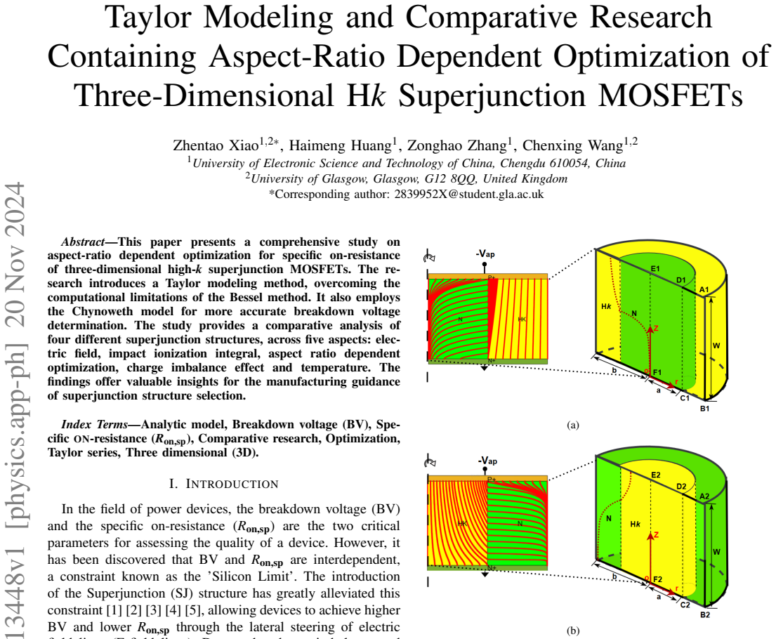
The load-bearing object is the closed-form electric-field expression $E_S(b,z)$ obtained by Taylor-expanding the potential in the radial direction around $r=b$ for the silicon region and $r=0$ for the high-k region, keeping only three terms and using the Poisson-equation boundary conditions. The expression depends on structural constants $T_c$, $T_d$, and $T_e$, which are functions of the region radii $a$, $b$ and the permittivity ratio $K$, with $T_c^2$ containing a dimensionless constant 1.42. This field expression feeds the Chynoweth impact-ionization integral to locate breakdown, and the optimization follows the critical-depletion and critical-breakdown methodology to minimize $R_{on,sp}$ under aspect-ratio variation.
What would settle it
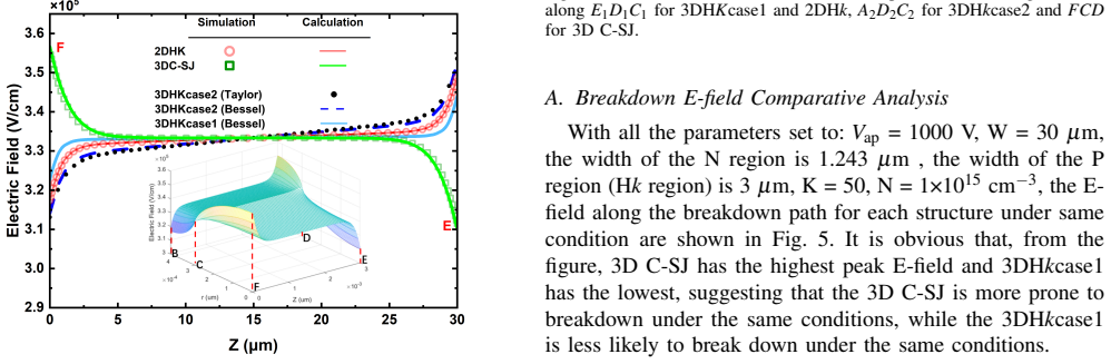
Take a 3DHkcase2 device with $a=2\,\mu\mathrm{m}$, $K=50$, $N=10^{15}\,\mathrm{cm}^{-3}$, and $V_{\mathrm{ap}}=1000\,\mathrm{V}$, compute the electric field along the A2B2 path from the Taylor expression, and compare it with a fine-mesh 3D TCAD simulation; if the deviation exceeds about 2.5% away from $z=0$, or if matching requires re-fitting the 1.42 constant when $a/b$ or $K$ changes, the universality claim behind the optimization collapses.
Extended reading notes
Core claim
The central discovery is that the electric field at the breakdown path $r=b$ of the 3DHkcase2 structure can be written in closed form from a three-term Taylor expansion of the potential, giving Eq. (8). Combined with the Chynoweth impact-ionization integral and the aspect-ratio optimization constraints of critical depletion and critical breakdown, this yields optimized doping, height, and specific on-resistance for a target breakdown voltage. The method reproduces Bessel-method and TCAD simulation results with errors mainly below 2.5%, and it supports the claim that increasing aspect ratio lowers optimized specific on-resistance for the high-k structures. The optimized value 4.156 mΩ·cm² at BV=800 V, K=100, and aspect ratio 70 is presented as the outcome of this closed-form procedure.
Load-bearing premise
The load-bearing premise is that the dimensionless constant 1.42 in the structural constant $T_c^2$ is a universal constant for 3DHkcase2; if it was fitted to a narrow range of geometry or voltage, the closed-form field and the optimized on-resistance values lose their claimed generality.
Editorial extensions
If this is right
- Designers can compute optimized doping, height, and specific on-resistance for 3DHkcase2 directly from closed-form field expressions, avoiding iterative Bessel-function solves.
- Increasing aspect ratio, meaning a narrower N-region, lowers optimized specific on-resistance for the high-k structures at fixed breakdown voltage, so process capability for high aspect ratios directly buys performance.
- Among the four structures compared, 3D C-SJ reaches the lowest optimized specific on-resistance (3.488 mΩ·cm² at 800 V and K=50) but is the most sensitive to charge-imbalance errors, while all high-k structures are more robust to doping deviations.
- 3DHkcase2 beats 3DHkcase1 and 2DHk in optimized specific on-resistance by 120% and 26%, respectively, and also shows better switching speed and temperature robustness than 3DHkcase1.
- Boundary-curve formulas in the aspect-ratio versus breakdown-voltage plane give a quantitative rule for selecting between 2DHk, 3DHkcase1, and 3DHkcase2 for a given manufacturing capability.
Reading between the lines
- The geometric constants $T_c$, $T_d$, and $T_e$ are derived only for the cylindrical 3DHkcase2 layout; a natural extension, not tested in the paper, is to re-derive them for hexagonal or trench layouts and check whether the 1.42 coefficient remains unchanged.
- Because the paper finds 3D C-SJ lowest in on-resistance but worst in charge-imbalance robustness, a reliability-minded designer might accept a higher on-resistance to gain immunity to doping variations; the paper does not make that trade-off recommendation itself.
- The boundary-curve formulas could be inverted to solve for the maximum breakdown voltage achievable at a given on-resistance and aspect-ratio budget for each structure, which the paper does not do.
- A direct check outside the reported parameter set would be to simulate 3DHkcase2 at K=20 and BV=1200 V and compare the optimized specific on-resistance from the Taylor field against full TCAD, testing whether the claimed sub-2.5% error persists.
Editorial analysis
A structured set of objections, weighed in public.
Referee Report
Summary. The manuscript proposes an analytic Taylor-series model for the electric field in one type of three-dimensional high-k superjunction (3DHkcase2), corrects a potential expression from prior Bessel-based work, uses the Chynoweth impact-ionization model for breakdown, and performs aspect-ratio-dependent optimization of specific on-resistance. The central quantitative claim is an optimized Ron,sp of 4.156 mOhm.cm2 at BV=800 V, K=100, and ARS=70, with results validated against Bessel calculations and MEDICI simulations at selected points. A comparative analysis of 3D C-SJ, 2DHk, 3DHkcase1, and 3DHkcase2 covers electric field, ionization integral, optimization, charge imbalance, and temperature, yielding boundary-curve formulas for structure selection.
Significance. If the model derivation were complete, the paper would offer a computationally cheaper design tool than the Bessel method and extend aspect-ratio optimization to a structure previously lacking it. The manuscript's strengths include the comparative framework across four structures, the explicit optimization constraints (critical depletion and critical breakdown), and the use of independent MEDICI simulations as a check. The boundary-curve formulas in Fig. 8 are practical design aids. However, the presence of an unexplained dimensionless constant (1.42) in the central electric-field expression is load-bearing: it propagates through the breakdown integral and all optimized Ron,sp values. The claimed <2.5% error and the headline optimum therefore rest on a calibration-like parameter whose universality is not demonstrated.
major comments (3)
- [Section II-B, Eq. (6)] The coefficient 1.42 in T_c^2 appears without derivation or citation. T_c enters T_e and lambda, and therefore the electric field (Eq. 8), the impact-ionization integral, the breakdown condition, and all optimized Ron,sp values in Fig. 3 and Table I. If this constant was fitted to match the Bessel solution or simulation over a narrow parameter window, the claim that the Taylor method is an independent analytic model is not supported, and the <2.5% error claim in Fig. 2(c) may not generalize. Please provide a derivation from Eq. (5) and boundary conditions (3), or demonstrate (e.g., by sweeping a, b, K, N, Vap) that 1.42 is universal, or state it as a fitted parameter with the fitted range.
- [Section II-B, Eq. (5) to Eq. (6)] The transition is described only as 'through the calculation,' omitting the algebraic steps and, more importantly, the approximations controlling the truncation error of the Taylor expansion. In particular, the definition of lambda as [Te*sqrt(1-(b/Td)^2/2)]^{-1} and the neglect of terms beyond second order need justification for the full parameter range used later (e.g., K=20-100, ARS up to 70). Without these details, the reader cannot judge whether the model remains valid where A, B, D, E are evaluated.
- [Section II-C, Fig. 3(d) and Fig. 2(c)] The validation against Bessel and MEDICI is performed at selected points, and the error metric in Fig. 2(c) explicitly excludes z=0. While the authors argue z=0 is benign because the field is minimal there, the exclusion also removes the location where the Taylor approximation is likely worst. More importantly, because the 1.42 constant is not derived, the agreement in Fig. 3(d) is consistent with a calibrated model rather than independent confirmation. Please add a sensitivity study varying 1.42 (or its underlying parameters) and report how Ron,sp(opt) and the error plots change.
minor comments (6)
- [Throughout] The text uses both 'H k' and 'Hk' interchangeably; for example, 'H k-SJ' appears in the abstract while 'Hk-SJ' appears in Section I. Please unify the notation.
- [Section II.A] The word 'followes' should be 'follows,' and in Section II.C 'appiled' should be 'applied.'
- [Fig. 6] The label '3DHKcase1' is typeset with uppercase K, differing from the running text's '3DHkcase1.'
- [Section III.C] The text does not state explicitly which electric-field model (Taylor, Bessel, or the methodology of [10]) is used for 3D C-SJ, 2DHk, and 3DHkcase1 in Fig. 7; please clarify.
- [Section III.E] The temperature exponent values 2.2003 and 2.1516 are reported in the text, but their extraction from Fig. 10(a) is not described; please specify the fitting procedure.
- [Section IV.A] The statement 'As shown in Fig. 5 and Fig. 6, 3DHkcase1 ... is the most difficult one to break down' refers to figures from Section III; consider adding a direct cross-reference in the text.
Circularity Check
No load-bearing circularity: the 1.42 coefficient in T_c^2 is an unexplained derivation step, and the optimization recipe is taken from a published self-citation, but the central results are checked against independent MEDICI simulation.
full rationale
The claimed Taylor method is not equivalent to its inputs by construction. It starts from the same Poisson system (2) and boundary conditions (3) as the Bessel solution, and the resulting E-field expression (8) is validated against Bessel and, independently, against MEDICI TCAD simulations (Fig. 2b,c; Fig. 3d). The external simulation check gives the central optimization claim (e.g., 4.156 mOhm.cm2 at BV=800 V, K=100, ARS=70) content that is not forced by any fitted parameter in the paper. The main concern is Eq. (6): T_c^2 = -1/2[epsilon_S/epsilon_Hk a(a-b) - 1.42(a-b)^2] contains a dimensionless constant 1.42 that is stated as the result of "the calculation" but is not derived from (2)-(5) in the text. This is an omitted proof and a genuine robustness risk: T_c enters T_e, lambda, Eq. (8), the ionization integral, and the optimized Ron,sp. If 1.42 were fitted to the Bessel solution or to a narrow MEDICI window, the claimed <2.5% error would be partly a consistency check rather than an independent prediction. The manuscript does not say 1.42 was fitted, and the MEDICI comparisons span different N, Vap, and K, so I cannot exhibit a specific reduction of a prediction to its fit. The other flagged element is the self-citation to [10] for the aspect-ratio optimization methodology; that is a published external method co-authored by H. Huang, and its use here is application, not a circular premise. No unique theorem or ansatz is smuggled in via self-citation. Verdict: no demonstrated circularity, but the unexplained coefficient and the load-bearing self-cited methodology justify a score of 2 rather than 0.
Assumptions & free parameters
free parameters (2)
- 1.42 dimensionless constant in T_c^2 =
1.42
- Temperature exponent of Ron,sp for 3DHkcase1 =
2.2003 at lower N, 2.1516 at higher N
assumptions (5)
- domain assumption Taylor expansions of VS and VHk truncated after three terms accurately represent the potential across the full drift region, not just near r=b and r=0.
- domain assumption Avalanche breakdown occurs first along the electric-field line from A2 to B2 for 3DHkcase2.
- ad hoc to paper The constant 1.42 in T_c^2 is a universal structural constant for 3DHkcase2.
- domain assumption The 3D structure is well described by cylindrical symmetry with no theta dependence.
- domain assumption The Chynoweth impact ionization model with silicon parameters from [14] is accurate for these high-k devices.
Cite this review
Pith. "Pith review of Taylor Modeling and Comparative Research Containing Aspect-Ratio Dependent Optimization of Three-Dimensional Hk Superjunction MOSFETs." pith.science (2026). https://pith.science/paper/7EQE3XAY
@misc{pith2026241113448,
  author       = {Pith},
  title        = {Pith review of: Taylor Modeling and Comparative Research Containing Aspect-Ratio Dependent Optimization of Three-Dimensional Hk Superjunction MOSFETs},
  year         = {2026},
  howpublished = {\url{https://pith.science/paper/7EQE3XAY}},
  note         = {Machine review of arXiv:2411.13448}
}
read the original abstract
This paper presents a comprehensive study on aspect-ratio dependent optimization for specific on-resistance of three-dimensional high-k superjunction MOSFETs. The research introduces a Taylor modeling method, overcoming the computational limitations of the Bessel method. It also employs the Chynoweth model for more accurate breakdown voltage determination. The study provides a comparative analysis of four different superjunction structures, across five aspects: electric field, impact ionization integral, aspect ratio dependent optimization, charge imbalance effect and temperature. The findings offer valuable insights for the manufacturing guidance of superjunction structure selection
Figures


Figures from the paper (8 more)



Reference graph
Works this paper leans on
-
[10]
H. Huang, S. Xu, W. Xu, K. Hu, J. Cheng, H. Hu, and B. Yi, “Optimization and comparison of drift region specific on-resistance for vertical power hk mosfets and sj mosfets with identical aspect ratio,” IEEE Transactions on Electron Devices , vol. 67, no. 6, pp. 2463–2470, 2020
work page 2020
-
[1]
Optimization of the specific on-resistance of the coolmos/sup tm/,
X.-B. Chen and J. Sin, “Optimization of the specific on-resistance of the coolmos/sup tm/,” IEEE Transactions on Electron Devices , vol. 48, no. 2, pp. 344–348, 2001
work page 2001
-
[2]
Optimization of the porous-silicon-based super- junction power mosfet,
H. Ye and P. Haldar, “Optimization of the porous-silicon-based super- junction power mosfet,” IEEE Transactions on Electron Devices, vol. 55, no. 8, pp. 2246–2251, 2008
work page 2008
-
[3]
A. Strollo and E. Napoli, “Optimal on-resistance versus breakdown voltage tradeoff in superjunction power devices: a novel analytical model,” IEEE Transactions on Electron Devices , vol. 48, no. 9, pp. 2161–2167, 2001
work page 2001
-
[4]
Theory of a novel voltage-sustaining layer for power devices,
X. Chen, P. Mawby, K. Board, and C. Salama, “Theory of a novel voltage-sustaining layer for power devices,” Microelectronics Journal, vol. 29, no. 6, pp. 1005–1011, 1998
work page 1998
-
[5]
X.-B. Chen, H.-Q. Yang, and M. Cheng, “New “silicon limit” of power devices,” Solid-State Electronics, vol. 46, no. 9, pp. 1185–1192, 2002
work page 2002
-
[6]
H. Huang, Y . Xu, H. Li, Z. Zhang, Y . Li, H. Zhang, J. Cheng, B. Yi, Z. Wang, and G. Zhang, “Optimization and comparison of specific on-resistance for superjunction mosfets considering three-dimensional and insulator-pillar concepts,” IEEE Transactions on Electron Devices , vol. 69, no. 3, pp. 1162–1168, 2022
work page 2022
-
[7]
Theory of 3-d superjunction mosfet,
H. Kang and F. Udrea, “Theory of 3-d superjunction mosfet,” IEEE Transactions on Electron Devices, vol. 66, no. 12, pp. 5254–5259, 2019
work page 2019
Show all 14 references
-
[8]
The minimum specific on-resistance of 3-d superjunction devices,
W. Zhang, K. Zhang, L. Wu, Y . Sun, X. Guo, Z. Wang, M. Qiao, Z. Li, and B. Zhang, “The minimum specific on-resistance of 3-d superjunction devices,” IEEE Transactions on Electron Devices , vol. 70, no. 3, pp. 1206–1210, 2023
2023
-
[9]
Vertical power h k-mosfet of hexagonal layout,
X. Lyu and X. Chen, “Vertical power h k-mosfet of hexagonal layout,” IEEE Transactions on Electron Devices , vol. 60, no. 5, pp. 1709–1715, 2013
2013
-
[11]
Numerical solutions for electric field lines and breakdown voltages in superjunction-like power devices,
H. Huang, K. Hu, W. Xu, S. Xu, W. Cui, W. Zhang, and W. T. Ng, “Numerical solutions for electric field lines and breakdown voltages in superjunction-like power devices,” IEEE Transactions on Electron Devices, vol. 67, no. 9, pp. 3898–3902, 2020
2020
-
[12]
Modeling power vertical high- k mos device with interface charges via superposition methodology- breakdown voltage and specific on-resistance,
Z. Wang, X. Wang, and J. B. Kuo, “Modeling power vertical high- k mos device with interface charges via superposition methodology- breakdown voltage and specific on-resistance,” IEEE Transactions on Electron Devices, vol. 65, no. 11, pp. 4947–4954, 2018
2018
-
[13]
A 650 v super-junction mosfet with novel hexag- onal structure for superior static performance and high bv resilience to charge imbalance: A tcad simulation study,
J. Park and J.-H. Lee, “A 650 v super-junction mosfet with novel hexag- onal structure for superior static performance and high bv resilience to charge imbalance: A tcad simulation study,” IEEE Electron Device Letters, vol. 38, no. 1, pp. 111–114, 2017
2017
-
[14]
Ionization rates for electrons and holes in silicon,
A. G. Chynoweth, “Ionization rates for electrons and holes in silicon,” Physical Review, vol. 109, no. 5, p. 1537, May 1958
1958
Reviewed August 12, 2026 · model on record in the stance chip above.
Discussion (0). Continue with ORCID to comment.