REVIEW 4 major objections 4 minor 13 references
uRWELL detector developments at Jefferson Lab for high luminosity experiments
T0 review · 4 major / 4 minor · reviewed 2026-08-12 · deepseek-v4-flash
Pith's one-line read A large-area μRWELL detector, the largest built so far, exceeded 90% tracking efficiency in cosmic-ray tests, supporting its use as the high-rate tracker for a future DDVCS measurement at Jefferson Lab.
desk verdict First data on the largest μRWELL yet, but the >90% efficiency number needs a denominator. read the letter →
The pith
A machine-rendered reading of the paper's core claim, the machinery that carries it, and where it could break.
The reading
What carries the argument
The central object is the μRWELL detector, a micro-pattern gas detector in which amplification happens in microwells in a polyimide foil and a sputtered diamond-like carbon layer provides charge evacuation and spark suppression. The PEP-dot grounding pattern makes the rate capability explicit by etching grounding dots through the upper copper and Kapton down to the resistive layer; the small prototypes vary the dot pitch, well pitch, and readout geometry to find the configuration that keeps efficiency at high flux. The large prototype uses 1 mm pitch U and V strips at ±10 degrees to test whether long, high-capacitance strips preserve efficiency and noise performance.
What would settle it
Expose the small prototypes to a beam and record efficiency and leakage current versus flux up to $10^6$ cm$^{-2}$ s$^{-1}$; if efficiency drops below the roughly 90% level or discharges appear at the operating voltages found in cosmic tests, the central claim is refuted.
Extended reading notes
Core claim
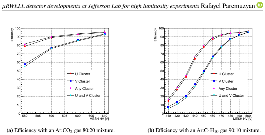
The central claim, stated as work in progress, is that μRWELL technology is a practical tracking option for the high-luminosity electron-scattering program at Jefferson Lab, including the never-measured DDVCS reaction. The evidence is a large-area prototype with an isosceles-trapezoid active area 145 cm at the base and 50 cm high, which the authors report as the largest μRWELL detector built so far. In cosmic-ray tests it reached above 90% efficiency for both U and V readout strips with Ar/CO2 (80/20) at 610 V and with Ar/isobutane (90/10) at 490 V; the isobutane mixture avoided the frequent leakage-current spikes seen with the CO2 mixture. The four 10 cm by 10 cm high-rate prototypes, varying PEP-dot pitch, well pitch, and readout, passed initial quality checks, so the remaining step is the planned early-2025 beam test at roughly 1 MHz per square centimeter.
Load-bearing premise
The whole plan assumes that the high efficiency and stable operation measured with slow cosmic-ray particles will still hold at roughly $10^6$ particles cm$^{-2}$ s$^{-1}$.
Editorial extensions
If this is right
- If the large-prototype efficiency pattern holds, a μRWELL-based forward tracker can be operated for CLAS12 at twice the standard luminosity, as the upgrade concept in the paper requires.
- Argon/isobutane (90/10) is the operating gas of choice for stability, while argon/CO2 remains usable if the high-voltage headroom is accepted.
- PEP-dot grounding leaves small periodic dead areas, so a final tracker design must either mask them or overlap detectors to maintain uniform efficiency.
- The four small prototypes give a direct comparison of dot pitch, well pitch, and readout type; the 1 cm dot-pitch prototype tests whether denser grounding buys the needed rate capability.
- The decisive claim for DDVCS, operation at about 1 MHz per square centimeter, is not yet made by this paper and depends on the early-2025 high-rate test.
Reading between the lines
- If the high-rate test reproduces the cosmic-ray efficiency, the same detector class could serve other large-acceptance, high-luminosity trackers, since the low material budget and simple construction make it comparatively inexpensive to scale.
- The observed dust-induced dead spots suggest the detector is robust to contamination; a practical consequence the paper does not develop is that ease of repair or replacement of the cathode foil should be part of the final mechanical design.
- The comparison of dot pitches is essentially a measurement of charge-evacuation time versus dead area; one should expect the rate ceiling to scale with dot density, and the beam test will reveal whether 1 cm pitch is sufficient or 2 cm pitch is already limiting.
Editorial analysis
A structured set of objections, weighed in public.
Referee Report
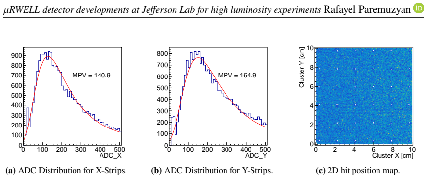
Summary. This proceedings paper reports R&D progress on Micro-Resistive Well (muRWELL) detectors at Jefferson Lab for future high-luminosity experiments (CLAS12 and SOLID upgrades). The authors describe four 10x10 cm prototypes with varying PEP-dot grounding pitch, readout layout, and well pitch, intended for operation at rates above 1 MHz/cm^2, and a large trapezoidal prototype (145 cm base, 50 cm height) claimed to be the largest muRWELL built to date. Cosmic-ray tests on the large prototype are presented: occupancy maps reveal a dead band, dust-induced inefficient spots, and periodic gaps between HV sections, and efficiency versus HV curves are shown for two gas mixtures, Ar/CO2 80:20 and Ar/Isobutane 90:10. The text claims >90% efficiency for U and V strips with both mixtures, but notes instability with Ar/CO2 and discharges with Ar/Isobutane at 500 V. High-rate beam tests are planned for early 2025 and are not reported in this manuscript.
Significance. If the reported efficiency and stability results are confirmed, this work is a useful step toward using muRWELL technology in high-luminosity tracking detectors. The paper is a conference proceedings contribution presenting preliminary but directly measured data, with clear descriptions of the prototype designs and an honest acknowledgment that high-rate validation is still pending. Its main strengths are the explicit design-parameter tables, the direct cosmic-ray measurements, and the identification of known dead regions in the large prototype. The principal limitation, as the authors themselves state, is the absence of any data at the target rate of about 1 MHz/cm^2; the current claims concern only low-rate cosmic tests. For the reported efficiency claim to be load-bearing, the analysis must be documented more rigorously.
major comments (4)
- [Section 4, Fig. 6, Section 5] The central claim of >90% efficiency is not well-defined because the paper never states how the known dead regions are treated in the efficiency denominator. Section 4 documents a ~20 mm wide dead band (HV issue), four dust-related low-occupancy spots, and a periodic 20 mm structure from gaps between HV sections. If these regions are included in the denominator, the dead band alone removes roughly 1.6% of the active area, and the gaps and spots add further losses; if they are excluded, the quoted >90% applies only to a subset of the detector and is not a true full-detector tracking efficiency. Please specify the exact geometric acceptance used in the efficiency calculation, and report efficiencies both with and without masking of the known defective regions.
- [Section 4, Fig. 6] The efficiency extraction method is not documented. The paper provides no error bars on the efficiency points, no number of cosmic tracks, no track-selection criteria (e.g., how reference tracks are formed from the GEM telescopes), no cluster-matching definition, and no threshold for what constitutes a hit. Without this information the reader cannot judge whether the observed differences between U and V layers are statistically significant or whether the plateaus are compatible with the quoted 90%. Please add a detailed description of the analysis chain and include statistical uncertainties on all efficiency points.
- [Section 4, Fig. 6 and Section 5] The text quotes '>90% efficiency for both U and V strips', but Fig. 6 shows four efficiency curves, including 'Any Cluster' and 'U and V Cluster'. The two-dimensional tracking efficiency, defined as a hit present in both U and V layers, is the lowest curve in the figure and is never quoted in the text or summary. For a real tracking detector, the coincident U-and-V efficiency is the relevant quantity for position measurement. Please report this value explicitly and discuss its magnitude; from the figure it appears to lie below 90% at the nominal operating voltages, which would weaken the summary statement.
- [Section 4, stability discussion] The stability comparison between the two gas mixtures is qualitative: the Ar/CO2 data show 'frequent spikes in leakage current', while Ar/Isobutane shows '1-2 discharges per hour' at 500 V. For a detector proposed for high-luminosity tracking, the discharge rate and its effect on the efficiency measurement must be quantified. In particular, state whether the efficiency points were taken during periods free of such spikes, what fraction of running time was affected, and whether any data were rejected because of instabilities.
minor comments (4)
- [Introduction, Eq. in paragraph 1] The luminosity unit is written as '10^37 cm^-2 s^-2' in the introduction (Section 1) and in the abstract as 'cm^-2 s^-1'; the correct unit is cm^-2 s^-1. Please correct the inconsistency.
- [Section 4, bullet 1] The dead band is described as 'x around in (410 cm - 430 cm)' but the figures use millimeter axes; this should presumably be '410 mm to 430 mm'.
- [Section 4, first paragraph] The claim that this is 'the largest muRWELL detector built so far' is not supported by a reference. If this is the authors' own assessment, it should be stated with a comparison to known previous large-area muRWELL constructions or else attributed to a source.
- [References] Reference [13] is an internal JLab wiki page; please check that this is accessible to the community or provide a more permanent reference, as the proceedings will be read by those outside JLab.
Circularity Check
No significant circularity; the efficiency results are direct measurements and self-citations are contextual only.
full rationale
This proceeding reports direct measurements of detector performance. The central claim, reaching >90% efficiency for the large μRWELL prototype with Ar/CO2 and Ar/Isobutane mixtures, is obtained from cosmic-ray test data and presented as efficiency-versus-HV curves in Fig. 6. No parameter is fitted to a subset of the data and then used to predict a closely related quantity; no equation is derived from an input that already contains the output. The paper's self-citations (refs. [3], [4] for LOIs, ref. [7] for prior μRWELL measurements, and ref. [13] for context on the CLAS12 luminosity upgrade) are motivational or contextual and are not used as evidence for the measured efficiency values. The authors also explicitly record the main limitation, namely that high-rate capability tests are planned for early 2025, which means the high-luminosity suitability claim is an extrapolation rather than a circular result. Concerns about the efficiency denominator and dead-region treatment noted in the skeptic analysis are experimental-reporting issues, not circularity. Therefore the derivation chain, such as it is, is self-contained with respect to circularity.
Assumptions & free parameters
assumptions (3)
- domain assumption The cosmic-ray test stand with two GEM reference trackers and scintillator triggers yields an unbiased estimate of μRWELL efficiency.
- domain assumption Cosmic-test efficiency and stability at low rate are representative of performance at the target rate near 1 MHz/cm2.
- ad hoc to paper The observed dead regions (HV gap, dust spots) do not materially affect the reported average efficiency.
Cite this review
Pith. "Pith review of uRWELL detector developments at Jefferson Lab for high luminosity experiments." pith.science (2026). https://pith.science/paper/UPVBYK7B
@misc{pith2026241113734,
  author       = {Pith},
  title        = {Pith review of: uRWELL detector developments at Jefferson Lab for high luminosity experiments},
  year         = {2026},
  howpublished = {\url{https://pith.science/paper/UPVBYK7B}},
  note         = {Machine review of arXiv:2411.13734}
}
abstract
One of the future plans at Jefferson Lab is running electron scattering experiments with large acceptance detectors at luminosities $> 10^{37}cm^{-2}s^{-1}$. These experiments allow the measurements of the Double Deeply Virtual Compton Scattering (DDVCS) reaction, an important physics process in the formalism of Generalized Parton Distributions, which has never been measured because of its small cross-section. The luminosity upgrade of CLAS12 or the SOLID detector makes Jefferson Lab a unique place to measure DDVCS. One of the important components of these high luminosity detectors is a tracking system that can withstand high rates of $\approx 1MHz/cm^{2}$. The recently developed Micro-Resistive Well (uRWELL) detector technology is a promising option for such a tracking detector by combining good position resolutions, low material budget with simple mechanical construction, and low production costs. In this proceeding, we will discuss recent developments and studies with uRWELL detectors at Jefferson Lab for future upgrades of the CLAS12 detector to study the DDVCS reaction.
Figures


Figures from the paper (3 more)


Reference graph
Works this paper leans on
-
[1]
J. Arrington, M. Battaglieri, A. Boehnlein, S. A. Bogacz, W. K. Brooks, E. Chudakov, I. Cloet, R. Ent, H. Gao and J. Grames,et al.Prog. Part. Nucl. Phys.127 (2022), 103985 doi:10.1016/j.ppnp.2022.103985 [arXiv:2112.00060 [nucl-ex]]
-
[2]
M. Guidal and M. Vanderhaeghen, Phys. Rev. Lett. 90 (2003), 012001 doi:10.1103/PhysRevLett.90.012001 [arXiv:hep-ph/0208275 [hep-ph]]
arXiv 2003
-
[3]
M. Guidal et al. Letter of Intent to JLab Program advisory committee: LOI12-16-004 https://www.jlab.org/exp_prog/proposals/16/LOI12-16-004.pdf
-
[4]
A. Camsonne et al. Letter of Intent to JLab Program advisory committee: LOI12-23-012. https://www.jlab.org/exp_prog/proposals/23/LOI12-23-012.pdf
- [5]
-
[6]
The Resistive-WELL detector: a compact spark-protected single amplification-stage MPGD
G. Bencivenni, R. De Oliveira, G. Morello and M. Poli Lener, JINST10 (2015) no.02, P02008 doi:10.1088/1748-0221/10/02/P02008 [arXiv:1411.2466 [physics.ins-det]]
work page Pith review arXiv 2015
- [7]
-
[8]
The micro-RWELL layouts for high particle rate
G. Bencivenni, R. de Oliveira, G. Felici, M. Gatta, M. Giovannetti, G. Morello, A. Ochi, M. Poli Lener, E. Tskhadadze, JINST05 (2019) no.02, P05014 doi:10.1088/1748- 0221/14/05/p05014 [arXiv:1903.11017 [physics.ins-det]]
work page Pith review arXiv 2019
Show all 13 references
-
[9]
Bencivenni, E
G. Bencivenni, E. De Lucia, R. de Oliveira, E. Di Meco, G. Felici, M. Gatta, M. Giovannetti, G. Morello, E. Paoletti, G. Papalino, M. Pinamonti, R. Pinamonti, M. Poli Lener, E. Sidoretti, R. Tesauro, Nucl. Instrum. Meth. A 1069 (2024), 169725 doi:10.1016/j.nima.2024.169725
2024
-
[10]
Martoiu, H
S. Martoiu, H. Muller and J. Toledo, doi:10.1109/NSSMIC.2011.6154414
2011
-
[11]
JLabFADC250manualhttps://www.jlab.org/Hall-B/ftof/manuals/FADC250UsersManual.pdf
-
[12]
G. Bencivenni’s Talk at RD51 Collaboration Meeting 2024, https://indico.cern.ch/event/1413681/contributions/6013367/attachments/2881828/5049134/ The%20micro-RWELL%20for%20high-rate.pdf
2024
-
[13]
Stepanyan et al., https://wiki.jlab.org/physdivwiki/images/a/a9/CLAS12_high_lumi.pdf 8
S. Stepanyan et al., https://wiki.jlab.org/physdivwiki/images/a/a9/CLAS12_high_lumi.pdf 8
Reviewed August 12, 2026 · model on record in the stance chip above.
Discussion (0). Continue with ORCID to comment.