REVIEW 4 major objections 4 minor 3 references
Low-Contrast BIC Metasurfaces with Quality Factors Exceeding 100,000
T0 review · 4 major / 4 minor · reviewed 2026-08-12 · deepseek-v4-flash
Pith's one-line read Shallow-etched silicon pairs reach a record quality factor of 101,486 under normal-incidence light.
desk verdict Record Q measurement is credible and worth publishing; the scattering-loss mechanism is suggestive but not established. read the letter →
The pith
A machine-rendered reading of the paper's core claim, the machinery that carries it, and where it could break.
The reading
What carries the argument
The load-bearing identity is the loss decomposition $Q^{-1} = Q_{\mathrm{r}}^{-1} + Q_{\mathrm{scat}}^{-1}$, in which the radiative part follows the quasi-BIC scaling $Q_{\mathrm{r}} = Q_0 \alpha^{-2}$ (with $\alpha$ the geometric asymmetry of the silicon pair) and the scattering part $Q_{\mathrm{scat}}$ is assumed to be a constant independent of $\alpha$ and extracted by fitting the measured Q. The mechanism that carries the argument is the low-contrast pair-rod design: etching the 400 nm silicon layer only 82.7 nm deep keeps the qBIC2 mode's field concentrated away from the sidewalls, so both $Q_{\mathrm{r}}$ and $Q_{\mathrm{scat}}$ are large. The critical coupling condition $Q_{\mathrm{r}} = Q_{\mathrm{scat}}$ is used in the sensing demonstration.
What would settle it
Fabricate metasurfaces with the same etching depth but deliberately varied sidewall roughness (for example, by changing the Bosch process passivation time), and measure Q at fixed small asymmetry; if Q does not change with roughness, or if the fitted Q_scat varies systematically with α, the paper's scattering-loss conclusion would be falsified.
Extended reading notes
Core claim
The central claim is that shallow-etched (low-contrast) silicon pair-rod metasurfaces supporting a higher-order quasi-BIC mode reach an experimental Q of 101,486, exceeding the previous all-dielectric BIC-metasurface record by about a factor of five and typical values by one to two orders of magnitude. The authors attribute this to two effects working together: the higher-order mode's electric field stays confined inside the silicon, keeping a large radiative Q even as the asymmetry parameter α grows, and the shallow etching (depth 82.7 nm on a 400 nm silicon layer) shrinks the sidewall area, cutting scattering loss from fabrication roughness. They support this by decomposing the measured Q as Q⁻¹ = Q_r⁻¹ + Q_scat⁻¹ and showing the extracted scattering term decreases as etching depth decreases, while the radiative term obeys Q_r = Q_0 α⁻².
Load-bearing premise
The entire quantitative argument depends on the assumption that the measured quality factor is the sum of a radiative rate that scales as α⁻² and a scattering rate that stays constant as α varies; if scattering loss actually depends on asymmetry, wavelength, or fabrication disorder tied to the pattern, the inferred reduction of scattering loss with shallower etching is not established.
Editorial extensions
If this is right
- The experimental Q factor of 101,486 is one to two orders of magnitude above typical qBIC metasurface values and about five times the prior all-dielectric metasurface record.
- The shallow-etch approach applies to other BIC metasurface configurations and other wavelengths, not just silicon pairs at telecom wavelengths.
- A BIC metasurface in water can track the resonance peak with sub-picometer wavelength fluctuations, yielding a limit of detection around 10⁻⁵ for refractive index changes.
- The optically measured Q in the small-asymmetry limit is set by the fabrication-quality floor Q_scat, so further Q gains require reducing sidewall roughness rather than only increasing radiative Q.
Reading between the lines
- One natural extension the authors leave implicit: the same shallow-etch strategy should suppress scattering in other materials (e.g., silicon nitride or TiO2) where sidewall roughness is the dominant loss, so Q above 10⁵ should be reproducible in other systems.
- A testable consequence: if Q_scat is truly a geometric property of the etch depth, then two devices with the same d but different roughness levels (e.g., from different Bosch process parameters) should show measurable differences in Q; this would verify that the Q gain comes from reduced scattering rather than from a changed radiative mode.
- The paper measures only one incident polarization; checking whether the ultrahigh Q persists for arbitrary linear polarization would determine whether the design can be used in unpolarized or polarization-agnostic sensing environments.
Editorial analysis
A structured set of objections, weighed in public.
Referee Report
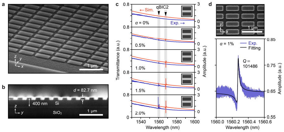
Summary. The paper reports silicon-on-insulator metasurfaces supporting higher-order quasi-bound states in the continuum (qBIC) in shallow-etched pair-rod unit cells. The authors experimentally demonstrate a Q factor of 101,486 at λ=1560.3 nm for an etch depth of 82.7 nm and asymmetry α=1%, and they attribute the ultrahigh Q to a combination of high radiative Q of the qBIC2 mode and reduced scattering loss in shallow-etched designs. The interpretation is supported by a Q-analysis that decomposes the measured Q as Q^{-1}=Qr^{-1}+Qscat^{-1}, with Qr taken from FEM simulations and Qscat fitted independently for three etch depths (82.7, 116.1, and 149.5 nm). The paper also demonstrates refractometric sensing in water with a limit of detection near 3×10^{-5} and a FOM up to 829.
Significance. If confirmed, the reported Q factor would be a substantial advance over previous BIC metasurface demonstrations, which have typically remained in the thousands or low tens of thousands, and the low-contrast / shallow-etch design is a simple and CMOS-compatible route to ultrahigh-Q operation. The systematic variation of etch depth and asymmetry, the combined FDTD/FEM simulations, and the comparison table with prior work are useful contributions. The sensing demonstration adds practical value. However, the headline record and the mechanistic claim that shallow etching reduces scattering loss currently rest on a single Fano fit and on an assumed form of the loss model, so the significance can only be fully realized after the statistical and modeling concerns below are addressed.
major comments (4)
- [Figure 3b-d and Q-analysis paragraph] The central mechanistic claim that shallower etching raises Q by reducing scattering loss is supported only by fitting the experimental Q factors with Q^{-1}=Qr^{-1}+Qscat^{-1}, where Qscat is assumed independent of α and is fitted as a single value per etch depth. This assumption is not tested, and the qBIC mode profile changes with both α and d, so sidewall-roughness scattering can in principle depend on α. If Qscat has any α-dependence, the fitted value is a weighted average and the trend in Figure 3d may be biased. Please provide the fit residuals, report confidence intervals for Qscat, and compare the quality of fit with an α-dependent Qscat or with disorder-incorporating simulations. Without this, the stated design principle is not quantitatively established.
- [Figure 2d and abstract record claim] The headline Q factor of 101,486 is extracted from a single Fano fit of a single device, with no fitting uncertainty, no repeated-device statistics, and no discussion of how the sidebands mentioned for Figure 2c or the choice of fitting background affect the extracted linewidth. Because the record claim is a central result, please report the standard deviation or spread obtained from multiple nominally identical devices and multiple independent fits, show representative fit residuals, and state the criteria used to select spectra for Q extraction.
- [Figure 3b and Supporting Information S3] The small-α saturation in Figure 3b is interpreted as an inherent Qscat, but the experimental setup may impose a measurable Q ceiling: the tunable laser sweep speed, spectral resolution, NA=0.26 focused illumination, the 100×100 μm patterned aperture, and polarizer-based background suppression are not characterized. The fact that Qscat appears to saturate near 10^5 for d=49.3 nm (Figure S3) is also consistent with an instrument-limited floor rather than a material or fabrication limit. Please characterize the minimum measurable linewidth of the setup and include this contribution explicitly in the Q budget before concluding that the saturation originates from scattering loss.
- [Table 1 and abstract claim of record-high Q] Reference [18] (Huang et al., Nature Communications 2023) reports a Q factor of 2.4×10^5 in an all-dielectric metasurface, yet Table 1, which is captioned 'all-dielectric metasurfaces,' does not include it, and the text states that the present Q factor is one order of magnitude higher than the highest reported value of 18,511. If the record is intended to be restricted to BIC metasurfaces, this must be stated explicitly in both the abstract and Table 1; otherwise, the comparison is inaccurate and the 'record-high' claim is not supportable.
minor comments (4)
- [Figure 1d caption/paragraph] There is a typo in the sentence describing Figure 1d: 'low-contrast matesurfaces' should be 'low-contrast metasurfaces'.
- [Table 1 caption] The caption lists 'troidal dipole' as a resonance type; this should be 'toroidal dipole'.
- [Figure 2c and 2d] The text reports that small sidebands occasionally appear in the spectra and attributes them to structural variations or interference, but it does not describe how the Fano fitting treats these sidebands or how spectra with sidebands were excluded. Please specify the fitting procedure and any selection criteria.
- [Figure 4c] The sub-picometer wavelength fluctuations are evaluated over approximately one minute; the authors note this is to minimize drift, but it would be useful to state explicitly that longer-term stability is not claimed.
Circularity Check
No circularity: the record Q factor is a direct measurement, and the Qscat analysis is a model-based interpretation rather than a prediction forced by construction.
full rationale
The headline result, Q = 101,486, is an experimentally measured value obtained by fitting a transmittance spectrum with a Fano function; it is not derived from the model, so there is no circularity in the central claim. The Q-analysis in Fig. 3 uses the standard decomposition Q^-1 = Qr^-1 + Qscat^-1, with Qr obtained from FEM eigenfrequency calculations and Qscat fitted to the measured Q values. The paper then plots the fitted Qscat versus etching depth d and interprets the trend as reduced scattering losses. This is a data-fitting and modeling interpretation, not a prediction that reduces by construction to its own inputs: Qscat is an extracted parameter, and the trend across d is read from the data rather than asserted from the fit itself. The inverse-square relation Qr = Q0 alpha^-2 is attributed to external literature [23], not to the present authors. The self-citations [35,41] are used only for context in sensing comparisons and critical-coupling motivation; they are not load-bearing in the derivation. No uniqueness theorem is imported from the authors' prior work, no ansatz is smuggled in via citation, and no known result is merely renamed. The skeptic's concern that Qscat may depend on alpha or absorb experimental floors is a model-validity and robustness issue, not circularity. Therefore the paper receives a circularity score of 0.
Assumptions & free parameters
free parameters (3)
- Q0 per etching depth =
not stated numerically
- Qscat per etching depth =
not stated numerically
- Fano line-shape parameters =
amplitude, width, phase, background per spectrum
assumptions (6)
- standard math Maxwell's equations, as implemented in the commercial FDTD and FEM solvers, correctly model the infinite periodic metasurface.
- domain assumption Silicon and the buried oxide (BOX) have negligible material absorption in the 1500-1900 nm wavelength range.
- domain assumption A 2000 nm BOX layer is thick enough to suppress leakage loss to the bottom silicon substrate.
- domain assumption The radiative Q of qBIC modes follows the inverse-square law Qr = Q0 alpha^-2.
- ad hoc to paper Qscat (scattering-limited Q) is independent of alpha and combines with Qr in inverse as Q^-1 = Qr^-1 + Qscat^-1.
- domain assumption A Fano line shape accurately describes the measured transmittance resonance, with negligible distortion from sidebands or background.
Cite this review
Pith. "Pith review of Low-Contrast BIC Metasurfaces with Quality Factors Exceeding 100,000." pith.science (2026). https://pith.science/paper/YIY3GIFP
@misc{pith2026241114101,
  author       = {Pith},
  title        = {Pith review of: Low-Contrast BIC Metasurfaces with Quality Factors Exceeding 100,000},
  year         = {2026},
  howpublished = {\url{https://pith.science/paper/YIY3GIFP}},
  note         = {Machine review of arXiv:2411.14101}
}
abstract
Dielectric metasurfaces operating at quasi-bound states in the continuum (qBICs) can achieve exceptionally high radiative quality ($\textit{Q}$) factors by introducing small asymmetries into their unit cells. However, fabrication imperfections often impose major limitations on the experimentally observed $\textit{Q}$ factors. In this study, we experimentally demonstrate BIC metasurfaces with a record-high $\textit{Q}$ factor of 101,486 under normal excitation of light in the telecom wavelength range achieved by employing low-contrast silicon pairs. Our findings show that such ultrahigh-$\textit{Q}$ factors can be attained by leveraging both the high radiative $\textit{Q}$ factors of higher-order qBIC modes and reduced scattering losses in shallow-etched designs. Additionally, we demonstrate stable sub-picometer-level wavelength fluctuations in water, with a limit of detection of $10^{-5}$ for environmental refractive index changes. The proposed approach can be extended to BIC metasurfaces with many other configurations and operating wavelengths for ultrahigh-$\textit{Q}$ applications in both fundamental physics and advanced devices.
Figures


Figures from the paper (1 more)

Reference graph
Works this paper leans on
-
[2]
Department of Condensed Matter Physics, Graduate School of Science, Hokkaido University, Kita 10, Nishi 8, Kita-ku, Sapporo 060-0810, Japan
-
[3]
* Email: watanabe.keisuke@nims.go.jp S1
Research Center for Electronic and Optical Materials, National Institute for Materials Science (NIMS), 1-1 Namiki, Tsukuba, Ibaraki 305-0044, Japan. * Email: watanabe.keisuke@nims.go.jp S1. Materials and methods Simulations: Transmittance spectra and electromagnetic mode profiles were simulated using a commercial FDTD solver (Ansys Lumerical). Radiative Q...
work page 2000
-
[293]
(4) Yang, Y.; Wang, W.; Boulesbaa, A.; Kravchenko, I
https://doi.org/10.1515/nanoph-2020-0373. (4) Yang, Y.; Wang, W.; Boulesbaa, A.; Kravchenko, I. I.; Briggs, D. P.; Puretzky, A.; Geohegan, D.; Valentine, J. Nonlinear Fano-Resonant Dielectric Metasurfaces. Nano Lett 2015, 15 (11), 7388–7393. https://doi.org/10.1021/acs.nanolett.5b02802. (5) Zhen, B.; Hsu, C. W.; Igarashi, Y.; Lu, L.; Kaminer, I.; Pick, A....
Reviewed August 12, 2026 · model on record in the stance chip above.
Discussion (0). Continue with ORCID to comment.