REVIEW 4 major objections 6 minor 31 references
A comprehensive study of the Spin-Hall effect of tightly focused linearly polarized light through a stratified medium in optical tweezers
T0 review · 4 major / 6 minor · reviewed 2026-08-12 · deepseek-v4-flash
Pith's one-line read Tightly focused light in stratified optical tweezers can show spin-Hall shifts of 1–3 µm, far larger than the sub-wavelength shifts usually reported.
desk verdict The NA/RI scan is a useful parameter study, but the headline 'multi-wavelength spin-Hall shift' is an artifact of measuring lobe separation rather than the actual centroid displacement. read the letter →
The pith
A machine-rendered reading of the paper's core claim, the machinery that carries it, and where it could break.
The reading
What carries the argument
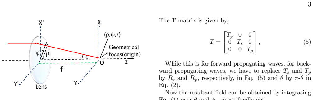
The central machinery is the Debye-Wolf vector diffraction integral extended to a four-layer stratified medium by a transfer function built from generalized Fresnel coefficients $T_s$, $T_p$, $R_s$, $R_p$ for s and p polarizations. The three diffraction integrals $I_0$, $I_1$, $I_2$ with Bessel-function kernels produce the focused field components; the spin-Hall shift is read off as the transverse separation between two intensity lobes of opposite spin density, and the phase difference between $E_x$ and $E_y$ is shown to control both the shift and the longitudinal spin angular momentum density $S_z$.
What would settle it
Repeat the Debye-Wolf simulation with the evanescent contributions retained and measure the transverse separation of the opposite-helicity lobes in a 1064 nm trap with a 1.814-index coverslip at NA = 1.2; if the predicted 2 µm shift disappears or the kink at NA ≈ 1.33 moves, the reported tuning strategy fails.
Extended reading notes
Core claim
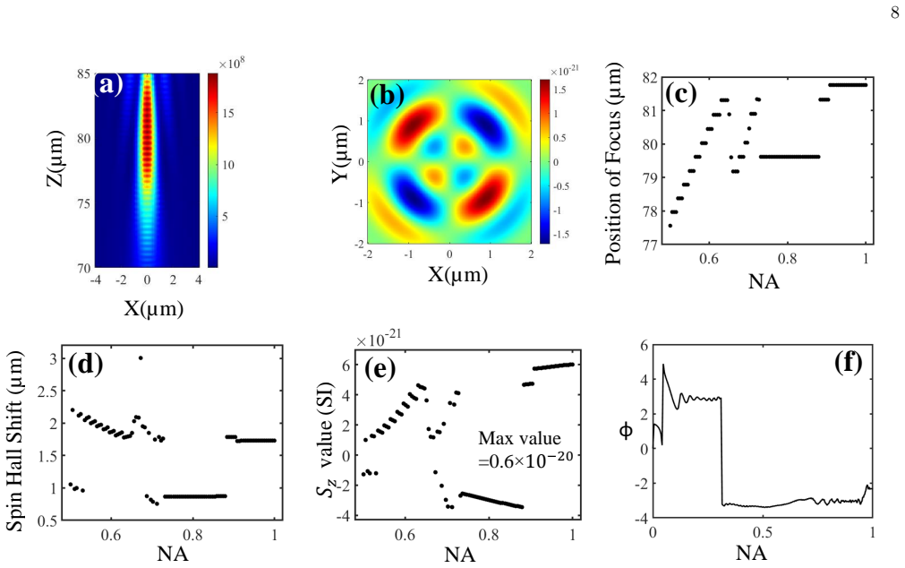
The paper claims that in optical tweezers, both the numerical aperture of the focusing lens and the refractive-index gradient of the stratified medium act as control knobs for the spin-Hall effect. For a 1064 nm linearly polarized Gaussian beam focused through a four-layer medium, the transverse separation of the two opposite-helicity intensity lobes reaches about 1 µm in the matched-coverslip case, about 2 µm in the mismatched case observed 2 µm away from focus, and 2–3 µm in air-objective arrangements. The longitudinal spin angular momentum density $S_z$ rises monotonically with NA except near NA ≈ 1.33, where the focused angular cone equals the critical angle of the coverslip–water interface and a kink appears in both $S_z$ and the spin-Hall shift. The phase difference between the orthogonal electric-field components $E_x$ and $E_y$ is identified as the single quantity that dictates both effects, with the shift tied to the geometric-phase gradient and $S_z$ depending on geometric and dynamic phase together.
Load-bearing premise
The results assume that the evanescent waves created by total internal reflection at the coverslip–water interface never reach the focal region, an assumption that breaks down near the critical angle NA ≈ 1.33 where these waves' decay length diverges.
Editorial extensions
If this is right
- In the matched-coverslip geometry the shift maximizes at NA = 1.1 with about 1 µm, then saturates beyond NA = 1.33, so the NA setting alone can select a shift regime.
- In the mismatched case the largest shift, about 2 µm, occurs 2 µm from focus for NA between 1.2 and 1.5, matching experimentally relevant trapping planes.
- Air-objective configurations produce the largest shifts, close to 2–3 times the laser wavelength, at NA near 0.66–0.67, while $S_z$ there is more than an order of magnitude smaller than in oil-immersion cases.
- Because $S_z$ grows with NA apart from the critical-angle kink, increasing NA should strengthen the spin torque on birefringent trapped particles.
- The critical-angle kink at NA ≈ 1.33 appears in both the shift and $S_z$, providing a sharp, observable signature of the stratified-medium interface.
Reading between the lines
- Since the paper computes $S_z$ from the electric field alone, and the magnetic contribution is usually equal in a nonmagnetic medium, the longitudinal spin density available to trapped birefringent particles may be roughly twice the reported values.
- The critical-angle kink offers a direct test: if the evanescent fields were included, the kink position and the shifts around NA ≈ 1.33 would be modified; measuring that region would separate interface effects from pure focusing effects.
- The enhanced shift mechanism could be exploited for spin-dependent sorting or rotation of particles without changing laser power, simply by choosing coverslip refractive index and NA.
- One could extend the calculation to circular or azimuthal input polarizations to see whether the shift and $S_z$ scaling with NA follows the same geometric-phase explanation.
Editorial analysis
A structured set of objections, weighed in public.
Referee Report
Summary. The paper presents Debye-Wolf diffraction-integral simulations of tightly focused linearly polarized light in a four-layer stratified medium, modeling optical-tweezer geometries. It sweeps objective numerical aperture and refractive-index configurations (oil-matched, oil-mismatched, and air-objective cases) and reports two outputs: a 'spin-Hall shift' (SHS) defined as the transverse separation between the extrema of opposite-sign longitudinal spin-density lobes, and the extremum value of the electric-only longitudinal SAM density Sz. The authors claim SHS values of about 1–3 μm, i.e., several times larger than the sub-wavelength shifts usually reported, and observe a kink in both SHS and Sz when the focusing angle reaches the critical angle of the coverslip-water interface. They interpret the trends through the phase difference between Ex and Ey, and through geometric versus dynamic phase contributions.
Significance. If the reported large SHS values were validated against the standard centroid-based definition of the spin-Hall shift, the paper would be a useful systematic study of how stratification and NA control spin-orbit interactions in optical tweezers, with potential applications in optomechanics and particle manipulation. The work is not circular: no parameters are fitted to data, and the fields are direct outputs of standard diffraction integrals. The phase-difference explanation for the kink at the critical angle is physically coherent and testable. However, the headline quantitative claim rests on a nonstandard SHS metric, and several input and modeling choices are not fully quantified; the significance of the central result is therefore conditional on additional analysis.
major comments (4)
- [Section III, Fig. 4 and Table I]
- [Section III, Eq. (8) and matched-case discussion]
- [Eq. (12) and Table II]
- [Section II, Eq. (8)]
minor comments (6)
- [Eq. (9)]
- [Figures 4–7]
- [Figs. 4(f)–7(f)]
- [Tables I and II]
- [Section III, matched-case text]
- [Abstract and Conclusion]
Circularity Check
No significant circularity: the SHS and Sz values are direct outputs of standard Debye-Wolf diffraction integrals with no fitted parameters; self-citations are contextual only.
full rationale
The derivation chain starts from the standard Debye-Wolf/Angular Spectrum formalism (Eqs. 1-9) with Fresnel coefficients set by the stated RI stratification and NA. The SAM density is computed from these fields via Eqs. 10-13, and the SHS is read off from the computed SAM-density lobes as described in Sec. III. No parameter is fitted to any target quantity, and the reported SHS/Sz values are not used as inputs anywhere in the calculation, so the central results do not reduce to their inputs by construction. The paper's citations to the authors' prior work (Refs. 20, 21, 30) appear when invoking the diattenuation parameter, experimental scenarios, or previously observed optomechanical effects; these citations are interpretive and contextual, not load-bearing for the numerical predictions. The phase-difference explanation of the NA dependence is a post hoc correlation with the same simulated fields, not an independent input. The operational definition of SHS as the separation between opposite-spin-density lobes differs from the common centroid-shift definition, and the claim of 'much larger' shifts should be read in that light; this is an interpretation/metric concern, not circularity. Overall the paper is self-contained against the external Debye-Wolf benchmark.
Assumptions & free parameters
free parameters (1)
- Incident Gaussian beam fill factor
assumptions (6)
- standard math Debye-Wolf angular spectrum integral is valid for the tightly focused field (Eq. 6).
- standard math Generalized Fresnel coefficients fully describe the stratified medium (Eqs. 8-9).
- domain assumption The media are lossless and nonmagnetic so Eq. (11) holds.
- ad hoc to paper Evanescent waves from total internal reflection can be neglected.
- ad hoc to paper SAM density can be computed from the electric field alone.
- domain assumption SHS is the separation between intensity lobes of opposite spin density.
Cite this review
Pith. "Pith review of A comprehensive study of the Spin-Hall effect of tightly focused linearly polarized light through a stratified medium in optical tweezers." pith.science (2026). https://pith.science/paper/F4NLUI5O
@misc{pith2026241114104,
  author       = {Pith},
  title        = {Pith review of: A comprehensive study of the Spin-Hall effect of tightly focused linearly polarized light through a stratified medium in optical tweezers},
  year         = {2026},
  howpublished = {\url{https://pith.science/paper/F4NLUI5O}},
  note         = {Machine review of arXiv:2411.14104}
}
read the original abstract
The optical Spin-Hall effect originates from the interaction between the spin angular momentum (SAM) and extrinsic orbital angular momentum (OAM) of light, leading to mutual interrelations between the polarization and trajectory of light in case of non-paraxial fields. Here, we extensively study the SHE and the resultant Spin-Hall shifts (SHS) in optical tweezers (OT) by varying the numerical aperture of objective lenses, and the refractive index (RI) stratification of the trapping medium. Indeed, we obtain much larger values of the SHS for particular combinations of NA and stratification compared to the sub-wavelength orders typically reported. We also observe that the longitudinal component of the spin angular momentum (SAM) density - which is responsible for the spin of birefringent particles in optical tweezers - changes more-or-less monotonically with the lens numerical aperture, except around values of the latter where the angle subtended by the focused light equals the critical angle for a particular RI interface. Our results may find applications in designing experiments for tuning the SHS and SAM induced due to SOI to generate exotic optomechanics of trapped particles in optical tweezers.
Figures


Figures from the paper (4 more)


Reference graph
Works this paper leans on
-
[1]
K. Y. Bliokh, A. Y. Bekshaev, and F. Nori, Extraordi- nary momentum and spin in evanescent waves, Nature communications 5, 3300 (2014)
2014
-
[2]
a coverslip, 3) the sample chamber, and 4) a top cov- erglass, acts as a modifier of the focused field. Two dif- ferent coverslips – one matching the RI of the immersion oil (i.e., RI 1.516), referred to as ’matched case’ and an- other with a mismatch (RI 1.814), referred to as ’mis- matched case’, are employed to alter the focused field in the sample cha...
-
[3]
M. V. Berry, Optical currents, Journal of Optics A: Pure and Applied Optics 11, 094001 (2009)
work page 2009
-
[4]
S. M. Barnett, L. Allen, R. P. Cameron, C. R. Gilson, M. J. Padgett, F. C. Speirits, and A. M. Yao, On the natures of the spin and orbital parts of optical angular momentum, Journal of Optics 18, 064004 (2016)
work page 2016
- [5]
-
[6]
S. Saha, N. Ghosh, and S. D. Gupta, Transverse spin and transverse momentum in structured optical fields, arXiv preprint arXiv:1806.03334 (2018)
work page Pith review arXiv 2018
-
[7]
K. Y. Bliokh, F. J. Rodr ´ ıguez-Fortu˜ no, F. Nori, and A. V. Zayats, Spin–orbit interactions of light, Nature Photonics 9, 796 (2015)
2015
-
[8]
V. Liberman and B. Y. Zel’dovich, Spin-orbit interaction of a photon in an inhomogeneous medium, Physical Re- view A 46, 5199 (1992)
work page 1992
Show all 31 references
-
[9]
Marrucci, E
L. Marrucci, E. Karimi, S. Slussarenko, B. Piccirillo, E. Santamato, E. Nagali, and F. Sciarrino, Spin-to- orbital conversion of the angular momentum of light and its classical and quantum applications, Journal of Optics 13, 064001 (2011)
2011
-
[10]
Onoda, S
M. Onoda, S. Murakami, and N. Nagaosa, Hall effect of light, Physical review letters 93, 083901 (2004). 10
2004
-
[11]
Leyder, M
C. Leyder, M. Romanelli, J. P. Karr, E. Giacobino, T. C. Liew, M. M. Glazov, A. V. Kavokin, G. Malpuech, and A. Bramati, Observation of the optical spin hall effect, Nature Physics 3, 628 (2007)
2007
-
[12]
Hosten and P
O. Hosten and P. Kwiat, Observation of the spin hall effect of light via weak measurements, Science 319, 787 (2008)
2008
-
[13]
X. Yin, Z. Ye, J. Rho, Y. Wang, and X. Zhang, Photonic spin hall effect at metasurfaces, Science339, 1405 (2013)
2013
-
[14]
Y. Qin, Y. Li, H. He, and Q. Gong, Measurement of spin hall effect of reflected light, Optics letters 34, 2551 (2009)
2009
-
[15]
X. Ling, X. Zhou, K. Huang, Y. Liu, C.-W. Qiu, H. Luo, and S. Wen, Recent advances in the spin hall effect of light, Reports on Progress in Physics 80, 066401 (2017)
2017
-
[16]
K. Y. Bliokh, D. Smirnova, and F. Nori, Quantum spin hall effect of light, Science 348, 1448 (2015)
2015
-
[17]
Korger, A
J. Korger, A. Aiello, V. Chille, P. Banzer, C. Wittmann, N. Lindlein, C. Marquardt, and G. Leuchs, Observation of the geometric spin hall effect of light, Physical review letters 112, 113902 (2014)
2014
-
[18]
K. Y. Bliokh, Geometrical optics of beams with vortices: Berry phase and orbital angular momentum hall effect, Physical Review Letters 97, 043901 (2006)
2006
-
[19]
Merano, N
M. Merano, N. Hermosa, J. P. Woerdman, and A. Aiello, How orbital angular momentum affects beam shifts in op- tical reflection, Physical Review A—Atomic, Molecular, and Optical Physics 82, 023817 (2010)
2010
-
[20]
Zhang, X.-X
J. Zhang, X.-X. Zhou, X.-H. Ling, S.-Z. Chen, H.-L. Luo, and S.-C. Wen, Orbit-orbit interaction and photonic or- bital hall effect in reflection of a light beam, Chinese Physics B 23, 064215 (2014)
2014
-
[21]
B. Roy, N. Ghosh, S. Dutta Gupta, P. K. Panigrahi, S. Roy, and A. Banerjee, Controlled transportation of mesoscopic particles by enhanced spin-orbit interaction of light in an optical trap, Physical Review A—Atomic, Molecular, and Optical Physics 87, 043823 (2013)
2013
-
[22]
B. Roy, N. Ghosh, A. Banerjee, S. D. Gupta, and S. Roy, Manifestations of geometric phase and enhanced spin hall shifts in an optical trap, New Journal of Physics 16, 083037 (2014)
2014
-
[23]
Bliokh, C
K. Bliokh, C. Prajapati, C. Samlan, N. K. Viswanathan, and F. Nori, Spin-hall effect of light at a tilted polarizer, Optics letters 44, 4781 (2019)
2019
-
[24]
Y. Zhao, J. S. Edgar, G. D. Jeffries, D. McGloin, and D. T. Chiu, Spin-to-orbital angular momentum conver- sion in a strongly focused optical beam, Physical review letters 99, 073901 (2007)
2007
-
[25]
Richards and E
B. Richards and E. Wolf, Electromagnetic diffraction in optical systems, ii. structure of the image field in an apla- natic system, Proceedings of the Royal Society of Lon- don. Series A. Mathematical and Physical Sciences 253, 358 (1959)
1959
-
[26]
Wolf, Electromagnetic diffraction in optical systems-i
E. Wolf, Electromagnetic diffraction in optical systems-i. an integral representation of the image field, Proceedings of the Royal Society of London. Series A. Mathematical and Physical Sciences 253, 349 (1959)
1959
-
[27]
Rohrbach, Stiffness of optical traps: Quantitative agreement between experiment and electromagnetic the- ory, Physical review letters 95, 168102 (2005)
A. Rohrbach, Stiffness of optical traps: Quantitative agreement between experiment and electromagnetic the- ory, Physical review letters 95, 168102 (2005)
2005
-
[28]
Novotny and B
L. Novotny and B. Hecht, Principles of nano-optics (Cambridge university press, 2012)
2012
-
[29]
O. G. Rodr ´ ıguez-Herrera, D. Lara, K. Y. Bliokh, E. A. Ostrovskaya, and C. Dainty, Optical nanoprobing via spin-orbit interaction of light, Physical review letters 104, 253601 (2010)
2010
-
[30]
T¨ or¨ ok and P
P. T¨ or¨ ok and P. Varga, Electromagnetic diffraction of light focused through a stratified medium, Applied optics 36, 2305 (1997)
1997
-
[31]
Haldar, S
A. Haldar, S. B. Pal, B. Roy, S. D. Gupta, and A. Baner- jee, Self-assembly of microparticles in stable ring struc- tures in an optical trap, Physical Review A—Atomic, Molecular, and Optical Physics 85, 033832 (2012)
2012
Reviewed August 12, 2026 · model on record in the stance chip above.
Discussion (0). Continue with ORCID to comment.