REVIEW 4 major objections 4 minor 42 references
Stability of Crossed-Field Amplifiers
T0 review · 4 major / 4 minor · reviewed 2026-08-12 · deepseek-v4-flash
Pith's one-line read The RPCFA, a high-power 3 GHz crossed-field amplifier, is a stable amplifier only within a window of anode-cathode gap and cathode current; outside that window it becomes a driven or self-excited oscillator, and a Hilbert-transform phase…
desk verdict A useful diagnostic paper for crossed-field amplifiers, with a stability map that is qualitatively credible but quantitatively limited by an admitted simulation-experiment gap. read the letter →
The pith
A machine-rendered reading of the paper's core claim, the machinery that carries it, and where it could break.
The reading
What carries the argument
The load-bearing diagnostic is the instantaneous phase difference obtained from the Hilbert transform of the input and output RF voltage signals, defined through $\Delta\theta(t)=\arctan(H[x_i(t)]/x_i(t))-\arctan(H[x_o(t)]/x_o(t))$, which for slowly varying amplitudes reduces to a phase ramp proportional to the frequency difference $\Delta f(t)$ plus phase noise. A constant phase difference indicates an ideal amplifier; a linear phase ramp indicates a constant frequency offset; a sudden large phase jump marks a transition of operating state. The physical backdrop is Brillouin flow, which supplies the Hull cutoff field $B_H$, the Buneman-Hartree synchronization condition, and the fact that the electron layer contains velocities from zero up to the hub-top velocity; this is what lets slower electrons at about $0.175c$ interact with the high-Q $\pi$-mode. Cold-tube Q factors carry the geometric sensitivity: reducing the AK gap changes the $\pi$-mode Q by over an order of magnitude while leaving the dispersion relation nearly unchanged.
What would settle it
Measure the cold-circuit Q factor of the RPCFA's $\pi$-mode and $\pi/2$-mode as the anode-cathode gap is reduced from 20 mm to 10 mm; the paper's mechanism predicts the $\pi$-mode Q rises by roughly an order of magnitude (from about 62 to about 2000) while the dispersion curves shift by less than 15 MHz/mm. If the Q does not rise sharply, or if the zero-drive oscillation frequency does not jump upward as the gap closes, the central stability explanation fails. On the diagnostic side, one could take a shot at a 12.5 mm gap with zero input and check for a sharp, correlated jump in Hilbert phase difference at the onset of the 3.16 GHz output; absence of such a jump would falsify the claimed transition marker.
Extended reading notes
Core claim
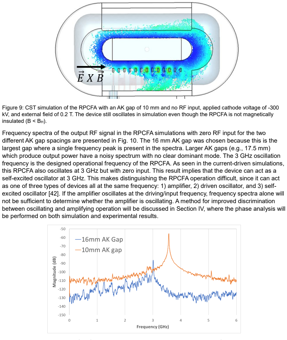
The paper's central claim is that the RPCFA has three operational states — stable amplification, driven oscillation, and self-excited oscillation — and that the state is controlled primarily by magnetic insulation, quantified by $B/B_H$, where $B_H$ is the Hull cutoff field. At the nominal 20 mm gap the device is a low-gain amplifier with about 5 dB gain; reducing the gap to 12.5 mm in experiment (10 mm in simulation) pushes $B/B_H$ near unity, and the device self-oscillates at a shifted frequency near 3.16 GHz (experiment) or 3.5 GHz (simulation) without input. The paper attributes the frequency upshift not to the dispersion relation, which changes little, but to the cold-circuit Q factors: as the gap closes, the $\pi$-mode Q rises from about 62 to about 2000 while the $\pi/2$-mode Q falls from 30 to 16, so the high-Q $\pi$-mode can be excited by slower electrons inside the Brillouin hub streaming at about $0.175c$. The authors propose three candidate mechanisms — resonant excitation of the high-Q mode, upper-band-edge absolute instability, or MILO-like operation near Hull cutoff — and state they have not identified which one dominates. They further claim that the Hilbert-transform phase difference $\Delta\theta(t)$ reveals the exact time of transition from amplification to oscillation, and use it to classify simulations and individual experimental shots.
Load-bearing premise
The paper's thresholds and frequency-shift mechanism rest on a CST particle-in-cell model that omits plasma formation, cathode ablation, outgassing, and slow-wave-structure electron emission, and the authors note that the simulated oscillation threshold (10 mm gap) differs from the experimental one (12.5 mm), so if the real plasma processes dominate near Hull cutoff the quantitative boundary and Q-based explanation may not transfer to the physical device.
Editorial extensions
If this is right
- If the stability boundary is real, CFA designers must treat AK gap and cathode current as stability knobs, not just performance knobs: a small reduction in gap can switch a zero-drive-stable tube into a self-excited oscillator.
- The Hilbert-phase diagnostic gives a single time-stamped marker for oscillation onset, so it can be used to compare simulations and shots on equal footing and to study how plasma diode closure effectively reduces the gap during a pulse.
- Because the $\pi$-mode (upper band edge) is the dangerous one, the paper's reasoning implies that operating on the backward-wave branch beyond the $\pi$-mode should improve stability against absolute instability.
- Near-Hull-cutoff operation shares features with MILOs, so insights and design rules from MILO research may transfer to CFAs; conversely, CFA phase diagnostics could be applied to MILO experiments.
Reading between the lines
- A natural extension the authors leave implicit: the same Hilbert phase-difference diagnostic could serve as a real-time feedback signal to detune or shut off the drive before an amplifier transitions into oscillation, which power monitoring alone cannot do reliably.
- The gap threshold discrepancy between simulation (10 mm) and experiment (12.5 mm) suggests that plasma and closure effects effectively reduce the electrical gap by roughly 2.5 mm; if that interpretation is right, one would expect the threshold to move with pulse length and cathode material, a testable prediction.
- The Q-factor sensitivity to geometry implies that cold-test measurements of mode Q at several gap spacings could act as a cheap screening tool for stability before full high-power operation.
Editorial analysis
A structured set of objections, weighed in public.
Referee Report
Summary. The paper examines the stability of the Recirculating Planar Crossed-Field Amplifier (RPCFA) through CST Particle Studio PIC simulations and experiments on the Michigan MELBA-C accelerator. It reports that the nominal 20 mm anode-cathode (AK) gap configuration is a zero-drive-stable amplifier with about 5 dB gain, and that the device can transition to driven or self-excited oscillation when the AK gap is reduced or the cathode current is increased. A cold-tube analysis indicates that the Q factors of the π/2 and π modes change substantially with AK gap, and the authors propose that this, together with lower-velocity electrons in the Brillouin hub, explains an observed frequency up-shift near the Hull cutoff. The paper further proposes a Hilbert-transform instantaneous phase-difference analysis to identify the time of transition from amplification to oscillation, and applies this method to both simulated and experimental signals.
Significance. If the results hold, the paper provides a useful diagnostic method for crossed-field amplifiers and a plausible mechanism for mode selection and stability loss near Hull cutoff. The experimental measurements across several AK gap spacings and the phase-analysis comparisons between simulation and experiment are valuable, and the authors are careful to identify limitations of their PIC model. The paper also makes a falsifiable prediction that reducing the AK gap can switch the RPCFA from stable amplification to self-excited oscillation, with a frequency up-shift that is observed in both simulation and experiment. However, several load-bearing quantitative claims rest on a model whose fidelity is explicitly limited, so the significance is currently conditional on those limitations being addressed or reframed.
major comments (4)
- [§II.A, §II.B, §III.A] The simulated nominal cathode current is 60 A (Fig. 4), whereas the measured current is 2.5 ± 0.5 kA (Sec. III.A), a factor-of-40 discrepancy. Because the current-driven oscillation threshold of 3 kA (Fig. 6d) and the associated claim that increasing cathode current drives the amplifier into oscillation are based on this same emission model, the quantitative current threshold is not supported by experiment. The authors acknowledge the missing plasma and emission-area physics, but the conclusion that 'oscillations can occur when the driving current exceeds some limit' is presented as a general result; it should be explicitly framed as a simulation prediction pending an emission-model benchmark.
- [§II.C, §III.B, Table 1] The zero-drive oscillation threshold differs between simulation and experiment: the simulation shows a dramatic transition below a 10 mm AK gap (Fig. 8), while the experiment shows the sharp rise in output power at 12.5 mm (Fig. 15). The authors attribute this to the lack of plasma and breakdown models, which is reasonable, but the paper nevertheless uses the simulated thresholds to make general claims such as 'when the AK gap is reduced below 17.5 mm, the RPCFA oscillates with zero input signal' (Sec. II.C). This quantitative boundary is not experimentally established, and the claim that the transition occurs 'around the same degree of magnetic insulation' is only qualitative, since Table 1 lists B/B_H = 1.18 at 12.5 mm and B/B_H = 0.95 at 10 mm.
- [§II.C, Fig. 10, Fig. 11] The cold-tube Q-factor values (30 to 16 for the π/2-mode and 62 to 2000 for the π-mode) are stated without any details of the cold-tube simulation, the extraction method, or the specific gap at which the reduced values apply. This matters because the Q-factor change is central to the proposed frequency-shift mechanism, yet the authors themselves note three competing explanations (high-Q resonant excitation, upper band-edge absolute instability, and MILO-like Hull-cutoff operation) and state that they have not identified which mechanism is responsible. The Q-factor analysis should either be documented sufficiently to be checked, or the frequency-shift explanation should be presented as a hypothesis rather than a conclusion.
- [§IV.A, §IV.C, Figs. 18–20] The paper claims that 'By using the Hilbert transform phase difference analysis, the precise time of transition can be identified' (Sec. IV.C), but the method is applied heuristically: the phase difference is examined visually in individual shots, and the authors acknowledge that late-time phase behavior becomes erratic and unreliable when output power falls to zero, e.g., due to RF breakdown or plasma diode closure (Sec. IV.C, Fig. 18). Since Eq. (4) is an identity for narrowband signals, it does not by itself distinguish amplifier, driven oscillator, or self-excited oscillator; the classification relies on interpreting slope changes and spikes. This is a useful diagnostic, but the claim of precision should be tempered, and an explicit criterion (e.g., a phase-slope threshold or a statistical measure) would be needed to support the stated level of certainty.
minor comments (4)
- [Fig. 8 caption] The caption states that the black line marks the transition to steady-state voltage at 200 ns, but no such line is visible in the figure as printed.
- [§IV.A, Eq. (1)] The Hilbert transform definition in Eq. (1) uses h(t) = 1/πt with the same symbol t in the integrand and the transform variable; it should be written as H{x}(t) = P.V. (1/π) ∫ x(τ)/(t−τ) dτ to avoid confusion.
- [References] Reference [11] contains a typo, 'Standford', and references [12] and [13] are DTIC PDFs that should include access dates for reproducibility.
- [Sec. II.C] The sentence 'Without simulating ablation and plasma generation in the gap and around the slow-wave structure, CST could not accurately predict operation near Hull cutoff for crossed-field devices in experiments' is important and should appear in the conclusions as well, since it directly limits the quantitative claims made elsewhere.
Circularity Check
No significant circularity: the oscillation thresholds, frequency shifts, and Hilbert-phase signatures are simulated or measured outputs, not inputs fitted to force the conclusions.
full rationale
I walked the derivation chain and found no step where a predicted quantity reduces by construction to an input parameter. The nominal CST simulation is benchmarked against earlier experiments, but the subsequent claims about reduced AK-gap and increased-current behavior are not fitted to the target thresholds; in fact, the simulated zero-drive oscillation threshold (10 mm) differs from the experimental threshold (12.5 mm), showing that the experimental result was not manufactured by the simulation. The Hilbert-transform phase analysis is a standard mathematical diagnostic: Eq. (4) follows from the stated slowly-varying amplitude/frequency assumptions applied to the definition of instantaneous phase, and the paper uses it consistently in both simulations and experiments, cross-checking frequency shifts against FFT spectra. The paper explicitly acknowledges that CST cannot accurately predict operation near Hull cutoff, which limits quantitative confidence but does not indicate circularity. Self-citations to prior Brillouin-flow and MILO work (e.g., refs. [15], [16], [31], [35], [38]) provide background assumptions and qualitative analogies rather than a load-bearing uniqueness chain that forces the paper's conclusions. No step exhibits self-definition, fitted-input-called-prediction, or renaming of a known result. The central claims remain independently supported by the presented simulations, experiments, and cold-tube analysis.
Assumptions & free parameters
assumptions (4)
- domain assumption Brillouin flow is the prevalent equilibrium state for distributed emission CFAs.
- domain assumption Input RF perturbs the Brillouin flow into spokes whose electrons convert potential energy to the growing RF signal.
- standard math RF signals have the slowly-varying amplitude and phase form x(t)=A(t)cos(2*pi*integral f dt + theta(t)), so the Hilbert transform yields the phase-difference formula Eq. (4).
- domain assumption The cold-tube eigenmode and Q-factor calculations represent the operating modes of the finite 12-cell slow-wave structure.
Cite this review
Pith. "Pith review of Stability of Crossed-Field Amplifiers." pith.science (2026). https://pith.science/paper/7C4YPDDC
@misc{pith2026241116066,
  author       = {Pith},
  title        = {Pith review of: Stability of Crossed-Field Amplifiers},
  year         = {2026},
  howpublished = {\url{https://pith.science/paper/7C4YPDDC}},
  note         = {Machine review of arXiv:2411.16066}
}
read the original abstract
This research examines the stability of crossed-field amplifiers (CFAs) and characterizes their different modes of operation: amplification, driven oscillation, and self-excited oscillation. The CFA used in this paper is the Recirculating Planar Crossed-Field Amplifier (RPCFA), which is a high power (MW) pulsed (300 ns) amplifier that operates around 3 GHz. Initially, the RPCFA is shown to be a stable amplifier with moderate gain (5.1 dB), but by either reducing the anode-cathode (AK) gap spacing or increasing the driving current, the amplifier operation transitions from amplification to oscillation. Depending on the operating conditions, these oscillations are either driven by the input RF signal or self-excited. These self-excited oscillations can have a lower synchronization phase velocity than the maximum velocity in the electron beam, implying that slower electrons within the Brillouin hub can interact with electromagnetic modes on the RF circuit. A cold tube analysis of the RPCFA shows that the Q-factor of certain modes on the RF circuit varies significantly when the AK gap geometry of the RPCFA is altered which leads to a discrete shift in operating frequency. The operation of the RPCFA close to Hull cutoff is found to share some key features of magnetically insulated transmission line oscillators (MILO) that could also explain the dramatic frequency shift. Instantaneous phase analysis by Hilbert transforms can be used, in conjunction with the frequency and output power analysis, to determine the onset of the transition from amplification to oscillation, and to characterize the oscillation.
Figures


Figures from the paper (11 more)




Reference graph
Works this paper leans on
-
[1]
G. B. Collins, Microwave Magnetrons, New York, NY , USA: McGraw-Hill MIT Radiation Laboratory Series, 1948
work page 1948
-
[2]
Okress, Crossed-Field Microwave Devices, New York, NY , USA: Academic Press, 1961
E. Okress, Crossed-Field Microwave Devices, New York, NY , USA: Academic Press, 1961
work page 1961
-
[3]
A. S. Gilmour, Klystrons, Travelling Wave Tubes, Magnetrons, Crossed-Field Amplifiers, and Gyrotrons, Artech House, 2011
work page 2011
-
[4]
P . H. Siegel, "Microwaves are everywhere: "ovens: from magnetrons to metamaterials"," IEEE Journal of Microwaves, vol. 1, no. 2, pp. 523-531, April 2021
work page 2021
-
[5]
The magnetron-type traveling-wave amplifier tube,
R. R. Warnecke, W. Kleen, A. Lerbs, O. Dohler and H. Huber, "The magnetron-type traveling-wave amplifier tube," Proceedings of the IRE, vol. 38, no. 5, pp. 486-495, May 1950
work page 1950
-
[6]
The effect of a uniform magnetic field on the motion of electrons between coaxial cylinders,
A. W. Hull, "The effect of a uniform magnetic field on the motion of electrons between coaxial cylinders," Physical Review, vol. 18, no. 1, pp. 31-57, July 1921
work page 1921
-
[7]
Description and operating characteristics of the platinotron - a new microwave tube device,
W. Brown, "Description and operating characteristics of the platinotron - a new microwave tube device," in Proceedings of the IRE, vol. 45, no. 9, pp. 1209-1222, September 1957
work page 1957
-
[8]
T. E. Ruden, "The amplitron as a high power, efficient, RF power source for long pulse, high resolution linear accelerators," IEEE Transactions on Nuclear Science, vol. 12, no. 3, pp. 169-173, June 1965
work page 1965
Show all 42 references
-
[9]
The continuous-cathode (emitting-sole) crossed-field amplifier,
J. F. Skowron, "The continuous-cathode (emitting-sole) crossed-field amplifier," Proceedings of the IEEE, vol. 61, no. 3, pp. 330-356, March 1973
1973
-
[10]
R. G. Carter, Microwave and RF Vacuum Electronic Power Sources, Cambridge University Press, 2018
2018
-
[11]
A study of the linear emitting-sole magnetron amplifier,
D. Chen, "A study of the linear emitting-sole magnetron amplifier," Ph.D. dissertation, Standford University, Palo Alto, CA, USA 1959
1959
-
[12]
CFA design improvement program volume I - Instrumented CFA studies,
G. K. Farney, "CFA design improvement program volume I - Instrumented CFA studies," Varian Associates, Inc., June 1978. https://apps.dtic.mil/sti/pdfs/ADA065735.pdf
1978
-
[13]
CFA design improvement program volume II - Computer modeling studies,
H. L. McDowell, "CFA design improvement program volume II - Computer modeling studies," Varian Associates, Inc., June 1978. https://apps.dtic.mil/sti/pdfs/ADA065736.pdf
1978
-
[14]
Simulation possibilities of vacuum electronic devices with CST PARTICLE STUDIOTM,
M. C. Balk, "Simulation possibilities of vacuum electronic devices with CST PARTICLE STUDIOTM," in IEEE International Vacuum Electronics Conference (IEEE 2008), pp. 459-460, Monterey, CA, 2008
2008
-
[15]
High-power recirculating planar crossed-field amplifier design and development,
S. C. Exelby, G. B. Greening, N. M. Jordan, D. A. Packard, D. Simon, Y . Y . Lau, B. W. Hoff and R. M. Gilgenbach, "High-power recirculating planar crossed-field amplifier design and development," IEEE Transactions on Electron Devices, vol. 65, no. 6, pp. 2361-2365, June 2018. 24
2018
-
[16]
High-power amplification experiments on a recirculating planar crossed-field amplifier,
S. C. Exelby, G. B. Greening, N. M. Jordan, D. A. Packard, D. Simon, Y . Y . Lau, B. W. Hoff and R. M. Gilgenbach, "High-power amplification experiments on a recirculating planar crossed-field amplifier," IEEE Transactions on Plasma Science, vol. 48, no. 6, pp. 1917-1922, June 2020
1917
-
[17]
Spoke characterization in re-entract backward wave crossed-field amplifiers via simulation,
M. Pearlman, D. N. Smithe, M. Worthington, J. Watrous, A. Garner and J. J. Browning, "Spoke characterization in re-entract backward wave crossed-field amplifiers via simulation," IEEE Transactions on Electron Devices, vol. 71, no. 8, pp. 5020-5027, August 2024
2024
-
[18]
Simulation of a pulsed 4.7 MW L-band crossed-field amplifier,
M. Pearlman, D. N. Smithe, C. Roark, M. Worthington, J. Watrous, A. Garner and J. J. Browning, "Simulation of a pulsed 4.7 MW L-band crossed-field amplifier," IEEE Transactions on Electron Devices, vol. 69, no. 12, pp. 7053-7058, 2022
2022
-
[19]
A circular crossed-field amplifier for in situ measurements, study of reentrant beam effects, and comparison with numerical simulation,
R. MacGregor, C. Chan, J. Ye and T. Ruden, "A circular crossed-field amplifier for in situ measurements, study of reentrant beam effects, and comparison with numerical simulation," IEEE Transactions on Electron Devices, vol. 41, no. 8, pp. 1456-1464, August 1994
1994
-
[20]
Computer studies of noise generation in crossed-field amplifiers,
D. Chernin, A. Drobot, G. Hilfer, M. Kress and S. Riyopoulos, "Computer studies of noise generation in crossed-field amplifiers," in IEEE International Electron Devices Meeting (IEEE 1991), pp. 593- 596, Washington DC, USA, 1991
1991
-
[21]
Feedback-induced noise in crossed-field devices,
S. Riyopoulos, "Feedback-induced noise in crossed-field devices," IEEE Transactions on Plasma Science, vol. 20, no. 3, pp. 360-369, June 1992
1992
-
[22]
Computer simulations of low noise states in a high-power crossed-field amplifier,
D. Chernin, “Computer simulations of low noise states in a high-power crossed-field amplifier,” IEEE Trans. Electron Devices, vol. 43, no. 11, pp. 2004-2010, November 1996
2004
-
[23]
Simulation of magnetrons and crossed-field amplifiers,
G. E. Dombrowsky, "Simulation of magnetrons and crossed-field amplifiers," IEEE Trans. Electron Devices, vol. 35, no. 11, pp. 2060-2067, November 1968
1968
-
[24]
Computer modeling of CFA’s using moving wavelength and trajectory tracing codes,
H. McDowell, “Computer modeling of CFA’s using moving wavelength and trajectory tracing codes,” in 1994 Microwave Power Tube Conference, Monterey, CA, paper 2D.4
1994
-
[25]
Crossed-field devices,
R. M. Gilgenbach, Y . Y . Lau, H. McDowell, K. L. Cartwright, and T. A. Spencer, "Crossed-field devices," in Modern Microwave and Millimeter Wave Power Electronics, edited by R. J. Barker, N. C. Luhmann, J. H. Booske, and G. S. Nusinovich, IEEE, Piscataway, NJ, 2004 Chap. 6
2004
-
[26]
J. C. Slater, Microwave Electronics, New York, NY: Van Nostrand, 1951
1951
-
[27]
Theory of the magnetron. I,
L. Brillouin, "Theory of the magnetron. I," Physical Review, vol. 60, no. 5, pp. 385-396, September 1941
1941
-
[28]
Symmetrical states and their breakup,
O. Buneman, "Symmetrical states and their breakup," in Crossed-Field Microwave Devices, New Yo r k , N Y, USA, Academic Press, 1961, pp. 209-233
1961
-
[29]
Numerical simulation of oscillating magnetrons,
A. Palevsky, G. Bekefi, and A. T. Drobot, “Numerical simulation of oscillating magnetrons,” Journal of Applied Physics, Vol. 52, no. 8, pp. 4938–4941, August 1981
1981
-
[30]
Resistive destabilization of cycloidal electron flow and universality of (near-) Brillouin flow in a crossed-field gap,
P . J. Christenson, D. P. Chernin, A. L. Garner and Y . Y . Lau, "Resistive destabilization of cycloidal electron flow and universality of (near-) Brillouin flow in a crossed-field gap," Physics of Plasmas, vol. 3, no. 12, pp. 4455-4462, December 1996
1996
-
[31]
Explicit Brillouin flow solutions in magnetrons, magnetically insulated line oscillators, and radial magnetically insulated transmission lines,
Y . Y . Lau, D. A. Packard, C. J. Swenson, J. W. Luginsland, D. Li, A. Jassem, N. M. Jordan, R. D. McBride and R. M. Gilgenbach, "Explicit Brillouin flow solutions in magnetrons, magnetically insulated line oscillators, and radial magnetically insulated transmission lines," IE...
2021
-
[32]
Limiting current in a relativistic diode under the condition of magnetic insulation,
M. Lopez, Y . Y . Lau, J. W. Luginsland, D. W. Jordan and R. M. Gilgenbach, "Limiting current in a relativistic diode under the condition of magnetic insulation," Physics of Plasmas, vol. 10, no. 11, pp. 4489-4493, November 2003
2003
-
[33]
Crossed field device
R. M. Gilgenbach, Y . Y . Lau, D. M. French, B. W. Hoff, J. Luginsland and M. Franzi, "Crossed field device". United States Patent 8,841,867, September 2014
2014
-
[34]
Brazed carbon fiber fabric field emission cathode,
B. W. Hoff, S. Beeson, D. Simon, W. Tang, R. Smith, S. C. Exelby, N. M. Jordan, A. Savir, R. M. Gilgenbach, P . D. Lepell and T. Montoya, "Brazed carbon fiber fabric field emission cathode," Review of Scientific Instruments, 064702, vol. 91, no. 6, June 2020
2020
-
[35]
On the two-dimensional Brillouin flow,
R. Revolinsky, C. Swenson, N. Jordan, Y . Y . Lau, R. M. Gilgenbach, “On the two-dimensional Brillouin flow,” Physics of Plasmas, 053109, vol. 31, no. 5, May 2024
2024
-
[36]
Transition to turbulence in a crossed-field gap,
P . J. Christenson, Y. Y . Lau, "Transition to turbulence in a crossed-field gap," Physics of Plasmas, vol. 1, no. 12, pp. 3725-3727, December 1994, Erratum vol. 3, no. 11, pp. 4293, November 1996
1994
-
[37]
Thermal electron flow in a planar crossed-field diode
D. Chernin, A. Jassem, Y . Y . Lau, "Thermal electron flow in a planar crossed-field diode", IEEE Transactions on Plasma Science, vol. 48, no. 9, pp. 3109-3114, September 2020
2020
-
[38]
Theory, simulation, and experiments on a magnetically insulated line oscillator (MILO) at 10 kA, 240 kV near Hull cutoff condition,
D. A. Packard, Y . Y . Lau, E. N. Guerin, C. J. Swenson, S. V. Langellotti, A. Jassem, D. Li, N. M. Jordan, J. W. Luginsland, R. D. McBride, R. M. Gilgenbach, “Theory, simulation, and experiments on a magnetically insulated line oscillator (MILO) at 10 kA, 240 kV near Hull cut...
2021
-
[39]
Absolute instability and transient growth near the band edges of a traveling wave tube,
F. Antoulinakis, P . Wong, A. Jassem and Y . Y . Lau, "Absolute instability and transient growth near the band edges of a traveling wave tube," Physics of Plasmas, 072102, vol. 25, no. 7, June 2018
2018
-
[40]
Microsecond electron beam diode closure experiments,
R. M. Gilgenbach, L. D. Horton, R. F. Lucey, S. Bidwell, M. Cuneo, J. Miller, and L. Smutek, “Microsecond electron beam diode closure experiments,” in Invited Talk, Proceedings of the IEEE Pulsed Power Conference, Crystal City, VA, 1985, p. 7
1985
-
[41]
H. E. Rowe, Signals and Noise in Communication Systems, Princeton, New Jersey: D. Van Nostrand Company. Inc., 1965
1965
-
[42]
Operation and theory of a driven single-mode electron cyclotron maser,
A. H. McCurdy, A. K. Ganguly and C. M. Armstrong, "Operation and theory of a driven single-mode electron cyclotron maser," Physical Review A, vol. 40, no. 3, pp. 1402-1421, August 1989
1989
Reviewed August 12, 2026 · model on record in the stance chip above.
Discussion (0). Continue with ORCID to comment.