REVIEW 3 major objections 4 minor 26 references
Properties of carbon-infused silicon LGAD devices after non-uniform irradiation with 24 GeV/c protons
T0 review · 3 major / 4 minor · reviewed 2026-08-11 · deepseek-v4-flash
Pith's one-line read Carbon-infused silicon LGAD timing detectors can still be operated at a single bias voltage after non-uniform proton irradiation with a tenfold dose gradient and peak fluence of 1e16 p/cm2, based on current and capacitance measurements.
desk verdict First non-uniform-irradiation LGAD IV/CV data with an honestly hedged common-bias conclusion; the timing question is deferred, so treat the headline as a depletion-level result, not a timing-certified one. read the letter →
The pith
A machine-rendered reading of the paper's core claim, the machinery that carries it, and where it could break.
The reading
What carries the argument
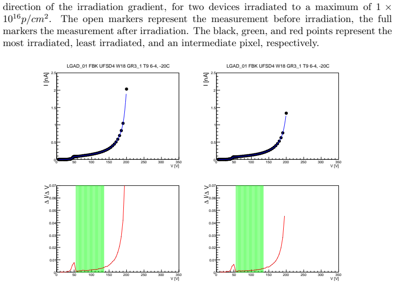
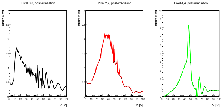
The analysis rests on the shape of the IV curve. A cubic-spline interpolation of the current versus voltage data is differentiated; the operating range of each pixel is taken from the initial peak of dI/dV (full depletion of the bulk) to the point where dI/dV again reaches 50% of that peak (onset of breakdown). The same derivative, weighted by V/I, defines the k-factor, whose first maximum gives the gain-layer voltage VGL used to quantify acceptor removal. This derivative-based definition of the operating voltage range is the mechanism that lets the paper compare pixels with very different dose on a common scale, and it is also the premise that would need to be validated against timing measurements.
What would settle it
Measure per-pixel gain, detection efficiency, and time resolution on the same devices after the same non-uniform irradiation. If the pixel exposed to 1e16 p/cm2 requires a bias voltage above the least-irradiated pixel's breakdown threshold to deliver the required timing resolution, the claimed single working point fails.
Extended reading notes
Core claim
On its own terms, the central finding is that a common high-voltage working point exists for all pixels in a single carbon-infused LGAD despite roughly a factor of ten in local proton fluence, up to a peak of 1e16 p/cm2. After irradiation at -20 C, every pixel studied reaches its operational voltage at or below 90 V, with leakage currents near 1 microampere, while the least irradiated pixels show the onset of breakdown only above about 200 V. For all four irradiated devices, the maximum operating voltage of the least irradiated pixel lies above the minimum operating voltage of the most irradiated pixel, which is the condition for a single bias setting. The same devices show an acceptor-removal fraction that decreases with dose and is higher than in some earlier uniform-irradiation studies, attributed to the carbon-infused, radiation-hard wafer choice. The paper frames this as an encouraging first step for using LGADs in forward proton timing, and lists efficiency and time-resolution tests as future work.
Load-bearing premise
The entire common-working-point conclusion rests on treating the current-voltage curve's knee and breakdown rise as the true usable operating window, even though the paper measures neither gain nor timing performance after irradiation.
Editorial extensions
If this is right
- Forward proton timing detectors at the High-Luminosity LHC could run non-uniformly irradiated LGADs with a single bias voltage, simplifying power and control systems.
- After doses up to 1e16 p/cm2, the irradiated pixels still show a defined operating knee below 90 V at -20 C, so the sensors are not immediately unusable after a year at peak dose.
- The least irradiated pixels retain margin before breakdown (onset above about 200 V), so the common operating point is not set by the undamaged corner.
- Acceptor removal, quantified through the gain-layer voltage, trends consistently with dose across different devices, suggesting the damage mechanism is the same as in uniform irradiation.
- CV measurements indicate that pixels receiving up to about 5e15 p/cm2 reach a similar capacitance as before irradiation, about 5-10 V higher, which supports the IV-based operating range for those pixels.
Reading between the lines
- If timing performance later confirms the IV-derived ranges, the single-common-voltage conclusion implies that per-pixel bias trimming is unnecessary; but if the most irradiated pixels need extra overdepletion for gain, per-pixel voltage control or stricter dose limits would be required.
- The three measured pixels trace one diagonal; a full two-dimensional map would reveal whether the guard-ring and inter-pad effects seen in the central pixel also appear elsewhere, which matters for detectors with larger pixel arrays.
- The higher surviving acceptor fraction than in earlier uniform-irradiation results suggests carbon-infused, radiation-hard wafers could tolerate even steeper dose gradients, which a dedicated uniform-dose comparison of the same wafer would test.
- Because annealing changes acceptor removal over time, the common working point found immediately after irradiation may drift during High-Luminosity LHC operation; storing and re-measuring at controlled annealing steps would show how much margin remains.
Editorial analysis
A structured set of objections, weighed in public.
Referee Report
Summary. The paper reports IV and CV measurements of carbon-infused FBK UFSD4 LGAD sensors before and after highly non-uniform 24 GeV/c proton irradiation, with peak fluences up to 1e16 p/cm2 and a dose gradient of about a factor of 10 across the sensor. The authors define per-pixel operating voltage ranges from the derivative of the IV curves and find an overlap between the minimum operating voltage of the most irradiated pixels and the maximum operating voltage of the least irradiated pixels, concluding that a common high-voltage working point may be found for all pixels. They also extract the acceptor-removal fraction using the k-factor method and compare it with previous uniform-irradiation results.
Significance. This is the first measurement of post-irradiation IV/CV behavior of LGADs under a non-uniform dose profile relevant to forward proton timing detectors at the HL-LHC. The experimental work is careful: measurements are done at -20 C with per-pixel before/after comparisons, hysteresis checks, multiple devices, and a non-irradiated control. The data are credible and the study addresses a practical question that has not been directly measured before. If the common-operating-voltage claim is confirmed by later timing measurements, it would be of direct practical value. The main weakness is interpretive: the operating range is defined from IV/CV features, not from timing performance, and the paper explicitly defers gain and time-resolution measurements to future work.
major comments (3)
- [Section 6.2 and Section 7 (Table 1)] The central claim that a common high-voltage working point may be found for all pixels is based entirely on IV-derived voltage ranges: the minimum is the voltage at the initial dI/dV peak (depletion knee) and the maximum is the voltage where dI/dV reaches 50% of that peak on the breakdown side. This is a depletion/breakdown proxy, not a timing-performance criterion. The paper's own acceptor-removal data (Section 6.3, Fig. 10) show that the gain-layer voltage drops to roughly 40-50% of its initial value at 1e16 p/cm2; maintaining sufficient gain for timing after such acceptor removal typically requires a bias well above the depletion knee, which could exceed the breakdown limit of the least irradiated pixel. Because no gain, efficiency, or time-resolution data are presented (as acknowledged in the final paragraph of Section 7), the conclusion 'a common high voltage working point may be found for all pixels' is not supported for the intended timing application. Please either (a) explicitly qualify the claim as an electrical operating point only, or (b) provide modeling or literature-based evidence that the IV/CV-defined range brackets the bias needed for adequate timing performance.
- [Section 6.4, Fig. 11] For the most irradiated pixel (0,0, 1e16 p/cm2), the 1/C^2 curve does not reach a plateau up to the maximum measured voltage of 65 V, so the full depletion voltage for that pixel is not actually bracketed by the CV data. Since the IV-derived minimum operating voltage for this pixel is about 70 V, the assertion that this pixel is above full depletion at its minimum operating voltage is not directly confirmed. Please either extend the CV measurement to higher voltages or explicitly state that the full-depletion voltage is a lower limit from the IV analysis only.
- [Section 6.3, Fig. 10] The horizontal dose axis uses per-pixel doses estimated from the BPM-derived beamspot profile, but the systematic uncertainty of this mapping is not quantified. The quoted 7% uncertainty is from foil activation only; the conversion from the beamspot shape to integrated dose per 1.3x1.3 mm2 pixel, especially across a steep gradient, likely has additional uncertainty. Please discuss or estimate this systematic effect; the qualitative conclusion is probably robust, but the comparison to uniform-irradiation data in Fig. 10 should account for this.
minor comments (4)
- [Figure 10] The axis labels in Fig. 10 appear garbled in the manuscript (e.g., '15 1016 10] 2 [p/cm2' and '(0) gl )/V Φ ( gl V'). Please fix the LaTeX rendering of the axis titles.
- [Section 6.2] The choice of 50% of the initial dI/dV peak as the definition of the maximum operating voltage is arbitrary; please add a sentence discussing the sensitivity of the overlap in Table 1 to this threshold, or cite a prior justification.
- [Section 4] The sentence 'The dose measured at the center of the beam was found to be 3-11% higher than the nominal target, with an uncertainty of 7%' is ambiguous: clarify whether the 7% uncertainty applies to the foil activation measurement of the absolute dose or to the correction factor.
- [Figures 5 and 6] The captions of Figs. 5 and 6 do not explicitly state which color corresponds to which pixel for the pre-irradiation open markers; the text does this, but a short caption note would improve readability.
Circularity Check
No circularity: the common-working-point conclusion is read directly from independent IV/CV measurements, with no fitted parameter or self-citation load-bearing.
full rationale
The derivation is self-contained and data-driven. The paper measures IV/CV curves before and after non-uniform irradiation and extracts per-pixel operating voltage ranges using a visibly specified dI/dV derivative criterion (Section 6.2). The central conclusion — that a common high-voltage setting exists for all pixels — follows directly from comparing the measured lower bounds of the most irradiated pixels (50-85 V) with the measured upper bounds of the least irradiated pixels (180-200 V) in Table 1. No parameter is fitted to reproduce that comparison; the VGL/acceptor-removal analysis is a secondary study using the literature k-factor method [25] and is not used to derive the main working-point result. The paper explicitly limits its conclusion to IV/CV behavior and defers efficiency and time-resolution measurements to future work (Section 7), which correctly scopes the claim. The only caveat — that the IV/CV knee is a proxy rather than a timing-performance metric — is a validity concern, not a circularity. No self-citation is load-bearing; references to prior uniform-irradiation studies are used for external comparison only.
Assumptions & free parameters
free parameters (2)
- Vmax threshold (50% of initial dI/dV peak) =
50% of the peak dI/dV
- Smoothing window for k-factor/VGL =
5 V pre-irradiation, 1 V post-irradiation
assumptions (3)
- domain assumption The BPM-derived beamspot profile is an accurate proxy for the pixel-by-pixel accumulated dose.
- domain assumption The first maximum of the k-factor dI/dV * V/I tracks the gain-layer depletion voltage, so its dose-dependent shift measures acceptor removal.
- domain assumption The three measured pixels on each sensor are representative of the 25-pixel array.
Cite this review
Pith. "Pith review of Properties of carbon-infused silicon LGAD devices after non-uniform irradiation with 24 GeV/c protons." pith.science (2026). https://pith.science/paper/RL3N4PM3
@misc{pith2026241213780,
  author       = {Pith},
  title        = {Pith review of: Properties of carbon-infused silicon LGAD devices after non-uniform irradiation with 24 GeV/c protons},
  year         = {2026},
  howpublished = {\url{https://pith.science/paper/RL3N4PM3}},
  note         = {Machine review of arXiv:2412.13780}
}
abstract
Forward proton spectrometers at high-energy proton colliders rely on precision timing to discriminate signal from background. Silicon low gain avalanche diodes (LGADs) are a candidate for future timing detectors in these systems. A major challenge for the use of LGADs is that these detectors must be placed within a few mm of the beams, resulting in a very large and highly non-uniform radiation environment. We present a first measurement of the current and capacitance vs. voltage behavior of LGAD sensors, after a highly non-uniform irradiation with beams of 24 GeV/c protons at fluences up to $1\times10^{16} p/cm^{2}$.
Figures


Figures from the paper (8 more)





Reference graph
Works this paper leans on
-
[1]
Diamond Detectors for the TOTEM Timing Upgrade
G. Antchev et al. [TOTEM], JINST 12, no.03, P03007 (2017) doi:10.1088/1748-0221/12/03/P03007 [arXiv:1701.05227 [physics.ins- det]]
work page Pith review arXiv 2017
-
[2]
E. Bossini [CMS and TOTEM], Nucl. Instrum. Meth. A 1047, 167823 (2023), doi:10.1016/j.nima.2022.167823
arXiv 2023
-
[3]
Timing Performance of a Double Layer Diamond Detector
M. Berretti, E. Bossini, M. Bozzo, V. Georgiev, T. Isidori, R. Lin- hart and N. Turini, JINST 12, no.03, P03026 (2017) doi:10.1088/1748- 0221/12/03/P03026 [arXiv:1612.09140 [physics.ins-det]]
work page Pith review arXiv 2017
-
[4]
E. Bossini, D. M. Figueiredo, L. Forthomme and F. I. Garcia Fuentes, CMS Note CERN-CMS-NOTE-2020-007, 2020
work page 2020
-
[5]
E. Bossini and N. Minafra, Front. in Phys. 8, 248 (2020) doi:10.3389/fphy.2020.00248
-
[6]
E. Bossini [CMS and TOTEM], JINST 15, no.05, C05054 (2020) doi:10.1088/1748-0221/15/05/C05054 [arXiv:2004.11068 [physics.ins- det]]
work page Pith review arXiv 2020
-
[7]
CMS Collaboration, Detector Performance Note CMS-DP-2024-118; CERN-CMS-DP-2024-118, 2024
work page 2024
-
[9]
Cerny [ATLAS], PoS Vertex2019, 055 (2020) doi:10.22323/1.373.0055 15
K. Cerny [ATLAS], PoS Vertex2019, 055 (2020) doi:10.22323/1.373.0055 15
Show all 26 references
-
[10]
Arcidiacono [CMS and TOTEM], Nucl
R. Arcidiacono [CMS and TOTEM], Nucl. Instrum. Meth. A 845, 16-19 (2017), doi:10.1016/j.nima.2016.05.114
2017 doi
-
[11]
J. N. Butler et al. [CMS], Technical Design Report CERN-LHCC-2019- 003, CMS-TDR-020, 2019
2019
-
[12]
Tornago, ”Detector optimization and physics performance of the CMS Phase-2 Endcap Timing Layer”, Thesis CERN-THESIS-2023-004, 2023
M. Tornago, ”Detector optimization and physics performance of the CMS Phase-2 Endcap Timing Layer”, Thesis CERN-THESIS-2023-004, 2023
2023
-
[13]
ATLAS Collaboration, Technical Design Report CERN-LHCC-2020- 007, ATLAS-TDR-031, 2020
2020
-
[14]
CMS Collaboration, CMS Note CERN-CMS-NOTE-2020-008 [arXiv:2103.02752 [physics.ins-det]]
2020 arXiv
-
[15]
Ferrero, R
M. Ferrero, R. Arcidiacono, M. Barozzi, M. Boscardin, N. Car- tiglia, G. F. Dalla Betta, Z. Galloway, M. Mandurrino, S. Mazza and G. Paternoster, et al. Nucl. Instrum. Meth. A 919, 16-26 (2019) doi:10.1016/j.nima.2018.11.121 [arXiv:1802.01745 [physics.ins-det]]
2019 arXiv
-
[16]
K. Wu, X. Jia, T. Yang, M. Li, W. Wang, M. Zhao, Z. Liang, J. G. da Costa, Y. Fan and H. Cui, et al. Nucl. Instrum. Meth. A 1046, 167697 (2023) doi:10.1016/j.nima.2022.167697 [arXiv:2205.05025 [physics.ins- det]]
2023
-
[17]
Senger, A
M. Senger, A. Bisht, G. Borghi, M. Boscardin, M. Vignali Centis, F. Fi- corella, O. H. Ali, B. Kilminster, A. Macchiolo and G. Paternoster, Nucl. Instrum. Meth. A 1039, 167030 (2022) doi:10.1016/j.nima.2022.167030 [arXiv:2204.08739 [physics.ins-det]]
2022
-
[18]
M. Li, Y. Fan, B. Liu, H. Cui, X. Jia, S. Li, C. Yu, X. Yang, W. Wang and M. Zhai, et al. JINST 16, no.08, P08053 (2021) doi:10.1088/1748- 0221/16/08/P08053 [arXiv:2107.03563 [physics.ins-det]]
2021 arXiv
-
[19]
Y. Tan, T. Yang, S. Xiao, K. Wu, L. Wang, Y. Li, Z. Liu, Z. Liang, D. Han and X. Zhang,et al.Nucl. Instrum. Meth. A1010, 165559 (2021) doi:10.1016/j.nima.2021.165559 [arXiv:2006.11691 [physics.ins-det]]
2021
-
[20]
Padilla, C
R. Padilla, C. Labitan, Z. Galloway, C. Gee, S. M. Mazza, F. McKinney- Martinez, H. F. W. Sadrozinski, A. Seiden, B. Schumm and 16 M. Wilder, et al. JINST 15, no.10, P10003 (2020) doi:10.1088/1748- 0221/15/10/P10003 [arXiv:2004.05260 [physics.ins-det]]
2020 arXiv
-
[21]
Mulargia, R
R. Mulargia, R. Arcidiacono, G. Borghi, M. Boscardin, N. Cartiglia, M. Centis Vignalis, M. Costa, T. Croci, M. Ferrero and F. Fi- corella, et al. JINST 19, no.04, C04022 (2024) doi:10.1088/1748- 0221/19/04/C04022
2024 doi
-
[22]
Tumasyan et al
A. Tumasyan et al. [CMS and TOTEM], JINST 18, no.09, P09009 (2023) doi:10.1088/1748-0221/18/09/P09009 [arXiv:2210.05854 [hep- ex]]
2023 arXiv
-
[23]
Ravotti, B
F. Ravotti, B. Gkotse, M. Glaser, P. Lima, E. Matli and M. Moll, PoS TIPP2014, 354 (2014) doi:10.22323/1.213.0354
2014 doi
-
[24]
Ravotti, B
F. Ravotti, B. Gkotse, M. Glaser, P. Jouvelot, I. Mateu, V. Meskova, G. Pezzullo and J. M. Sallese, doi:10.18429/JACoW-ICALEPCS2019- WEPHA127
-
[25]
Bacchetta, D
N. Bacchetta, D. Bisello, A. Candelori, M. Da Rold, M. Descovich, A. Kaminski, A. Messineo, F. Rizzo and G. Verzellesi, Nucl. Instrum. Meth. A 461, 204-206 (2001) doi:10.1016/S0168-9002(00)01207-9
2001 doi
-
[26]
Moll, PoS Vertex2019, 027 (2020) doi:10.22323/1.373.0027
M. Moll, PoS Vertex2019, 027 (2020) doi:10.22323/1.373.0027
2020 doi
-
[27]
E. L. Gkougkousis, L. Castillo Garcia, S. Grinstein and V. Coco, J. Phys. Conf. Ser. 2374, no.1, 012175 (2022) doi:10.1088/1742- 6596/2374/1/012175 [arXiv:2111.06731 [physics.ins-det]]. 17
2022 arXiv
Reviewed August 11, 2026 · model on record in the stance chip above.
Discussion (0). Continue with ORCID to comment.