REVIEW 3 major objections 6 minor 45 references
All-optical radio-frequency phase detection for Rydberg atom sensors using oscillatory dynamics
T0 review · 3 major / 6 minor · reviewed 2026-08-16 · deepseek-v4-flash
Pith's one-line read A five-level closed-loop Rydberg excitation under finite detuning converts the phase, frequency, and amplitude of an RF field into oscillations of the probe-laser transmission at the loop detuning frequency, enabling I/Q readout with no…
desk verdict The closed-loop oscillation carrier is a genuine and well-modeled new idea; the stress-test's spatial phase-matching objection doesn't survive contact with the resonance condition, and the paper's biggest real gaps are experimental validation and a missing noise/sensitivity analysis. read the letter →
The pith
A machine-rendered reading of the paper's core claim, the machinery that carries it, and where it could break.
The reading
What carries the argument
The load-bearing object is the accumulated loop phase $\phi$, which is equal and opposite for clockwise and counter-clockwise loop amplitudes; adding the two paths produces the $\cos\phi$ interference term in Eq. (4). Under finite blue-laser detuning $\Delta_{25}$ the phase winds in time, so the probe transmission oscillates at $\Delta_{25}/2\pi$, and the oscillation lasts as long as the drive coherence because it does not depend on atomic decay rates. The analytic expression is built from continued-fraction ladder coherences plus this phase-dependent closed-loop term, and it is what connects a measured optical oscillation to the RF phase, amplitude, and detuning.
What would settle it
Tilt the RF arrival angle in a 3-cm cell so the projected spatial period $1/k_{\rm eff}$ shrinks toward the cell length and watch the demodulated I/Q amplitude: if the contrast collapses as predicted, the $k_{\rm eff}=0$ assumption is doing the work; if it survives, the spatial-averaging picture is wrong. A second check is to unlock one loop laser from the common phase reference and observe whether the recovered $\varphi_{\rm RF}$ starts to drift with laser phase noise.
Extended reading notes
Core claim
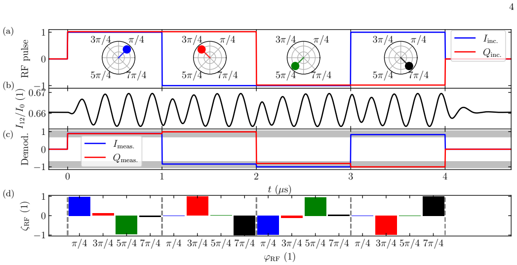
The paper's central claim is that a five-level closed loop—four optical fields plus the RF field under test, with the probe transition outside the loop—produces probe absorption that oscillates sinusoidally at the loop detuning when one loop field is finite-detuned. In the weak-probe, strong-coupling limit the coherence $\rho_{12}$ is given by Eq. (4): two ladder absorption terms plus a term $2C_{23}C_{34}C_{\rm RF}C_{52}\cos(\phi)$ whose phase is $\phi = \Delta_{25}t + \varphi_{\rm RF} + k_{\rm eff}z + k_{\rm eff} v t$. With all lasers phase-locked and the geometry co-linear so that $k_{\rm eff}=0$, the RF phase $\varphi_{\rm RF}$ appears directly as the phase of a global optical oscillation at $\Delta_{25}/2\pi$. Lindblad calculations for a 300-K cesium vapor show the analytic expression reproduces the steady-state oscillation to better than 3%, and a simulated four-symbol QAM pulse is recovered by demodulating $I_{12}(t)$ with Eq. (5) and applying a matched filter with Eq. (6).
Load-bearing premise
The method assumes the total wave vector of the loop cancels ($k_{\rm eff}=0$) and all laser fields are phase-locked to a common reference with zero relative phase; otherwise different velocity classes and spatial regions oscillate out of phase and the demodulated I/Q signal averages away.
Editorial extensions
If this is right
- Rydberg RF sensors can do phase-sensitive I/Q readout without an RF local oscillator, preserving the >100 GHz carrier bandwidth of the atomic transition.
- The target RF detuning can be read from the optical oscillation frequency when the loop detuning is known; the paper uses $\Delta_{25}=2\pi\times4$ MHz and observes 4-MHz oscillations in $I_{12}(t)$.
- The RF amplitude can be extracted from the oscillation amplitude once the other Rabi frequencies are known, with sensitivity comparable to non-looped all-optical Rydberg sensing.
- QAM symbols survive demodulation and matched filtering: the simulated sequence with phases $\pi/4$, $3\pi/4$, $5\pi/4$, $7\pi/4$ on 1-$\mu$s chips is recovered, with residual errors only from the transient response at phase jumps.
- Doppler averaging does not wash out the phase signal in the co-linear geometry because $k_{\rm eff}=0$ makes every velocity class oscillate at the same frequency; the transient decay, not the oscillation, sets the symbol-rate limit.
Reading between the lines
- If $k_{\rm eff}=0$ is relaxed controllably, the angle of arrival of the RF wave could be inferred from the loss of demodulation contrast or from a spatially resolved phase gradient, turning the averaging condition into a directional measurement.
- Because the down-conversion frequency is an optical loop detuning rather than an RF offset, the same readout should extend naturally to millimeter-wave and THz carriers that are hard to reach with conventional RF local oscillators.
- The comparison between zero-temperature and 300-K transients (95 ns versus 323 ns) suggests that colder atoms or slower transit would raise the symbol rate; a testable prediction is that the demodulated error floor follows the transient time constant at each temperature.
- Multiple simultaneous RF tones at different detunings should appear as distinct oscillation frequencies in the probe signal, allowing spectral separation in the demodulated output.
Signed reviews
Editorial analysis
A structured set of objections, weighed in public.
Referee Report
Summary. The paper proposes an all-optical method for measuring the phase (I/Q components) of a radio-frequency field using a five-level closed-loop excitation scheme in cesium. When one loop field (the 496 nm blue laser) is detuned by Δ25, the atomic response, and hence the probe-laser transmission, oscillates at Δ25, and the RF phase φRF is mapped onto the phase of these oscillations. The authors derive an analytic weak-probe expression, Eq. (4), and show that it reproduces the full Lindblad solution to better than 3% in the steady-state oscillations of Fig. 1(c). They then simulate decoding of a QPSK-like pulse sequence by demodulating the probe intensity at the detuning frequency and by matched filtering (Fig. 2). The central claims are that this method removes the need for an RF local oscillator while preserving the broad carrier bandwidth of Rydberg sensors, and that the RF phase, frequency, and amplitude can be recovered from the probe transmission.
Significance. The theoretical mechanism is internally consistent: the oscillation originates from closed-loop interference with a time-dependent phase, and the analytic formula is checked against an independent numerical integration. If the bandwidth claim were correct, the method would be a useful addition to Rydberg atom sensing, enabling phase-resolved measurements without an RF local oscillator. The paper also provides a detailed diagrammatic derivation of the weak-probe response for a closed-loop system, and the Supplemental Materials give enough parameters to reproduce the numerics. However, the work is entirely simulative, and the central '>100 GHz carrier bandwidth' claim is not supported by the model because the spatial phase-matching condition keff = 0 is frequency-selective. The authors should be credited for the clarity of the analytic derivation and for explicitly noting limitations such as neglected collisional and laser dephasing, but those limitations need to be addressed for the phase-recovery claims to be credible.
major comments (3)
- [Main text, Eq. (2); Supplemental Eq. (S3)] The statement after Eq. (2) that 'ϕ is spatially independent in the co-linear geometry, keff = k23 + k34 + kRF - k25 = 0' is not generally true; this equality holds only at one RF frequency. With the wavelengths in Fig. 1(b) (636 nm, 2262 nm, 496 nm), k23 + k34 - k25 = 2π(1/636 + 1/2262 - 1/496) nm^-1 ≈ -1.08×10^4 m^-1. Because kRF = 2πf/c, the cancellation keff = 0 requires f ≈ 515 GHz. For f in the claimed '>100 GHz' band (for example 10–100 GHz), keff is between roughly -8.7×10^3 and -1.1×10^4 m^-1, giving a spatial period of about 0.6–0.7 mm. Over the L = 3 cm cell, the cos(ϕ) term in Eq. (4) is suppressed by a factor of order 1/(|keff|L) ≈ 0.003, i.e. the phase-sensitive signal is effectively averaged out, exactly as warned in the Supplemental ('the signal over a spatial period averages out'). Thus the abstract's and conclusion's claim of simultaneous '>100 GHz carrier bandwidth' and all-optical phase readout is not supported by the model. Please provide an explicit analysis of keff(f) and either restrict the claim to a narrow band about the loop-closure frequency or propose a practical broadband compensation scheme.
- [Main text, Eq. (2); Supplemental Materials] The phase recovery is referenced entirely to the laser phases: Eq. (2) sets φeff = φ23 + φ34 + φRF - φ25, and the paper assumes all lasers are phase-locked with φij = 0. The Supplemental states that 'laser dephasing' is neglected. For a phase-sensitive method, this is a significant omission, because relative phase noise among the 636 nm, 2262 nm, and 496 nm lasers enters directly as an error in the measured RF phase. The paper provides no phase-noise budget, no tolerable laser linewidth, and no estimate of how the demodulated I/Q signals degrade with laser phase fluctuations. The closing claim that 'the achievable sensitivities are similar to non-looped systems' is therefore not substantiated. Please add a quantitative treatment of laser phase noise (and, if possible, collision-induced dephasing) and its effect on the phase measurement.
- [Main text, Eq. (5)] The demodulation uses an offset phase ϑ ≈ 10° 'to compensate the transient phase shift.' The value of ϑ is not derived from the system parameters and appears to be chosen so that the demodulated values match the known input phases in the simulation. In a real receiver the RF phase is unknown at the start of the measurement, and the optimal ϑ may depend on RF amplitude, previous symbols, and the transient history. Please explain how ϑ would be obtained in practice (e.g., from a calibration pulse or a training sequence) and quantify the sensitivity of the I/Q estimates to a mis-set ϑ.
minor comments (6)
- [Abstract and main text] The abstract says the phase, frequency, and amplitude are imprinted on the oscillatory dynamics, but the paper demonstrates phase and amplitude recovery and does not demonstrate frequency recovery. Please either demonstrate frequency estimation or adjust the wording.
- [Main text, Eq. (6)] The definition of the matched-filter template f(t) as 'a 1 µs RF pulse with the respective phase' is ambiguous, because the probe intensity oscillates at the detuning frequency (4 MHz), not at the RF carrier frequency. Please specify whether f(t) is the simulated I12(t) response or the RF pulse envelope, and explain why the latter would be a matched filter for an oscillation at Δ25.
- [Main text, near Eq. (4) and Fig. 1(c)] The statement that 'the oscillatory dynamics do not depend on any atomic decay rates' is too strong; the oscillation frequency is set by Δ25, but the amplitude and transient behavior in Eq. (4) and Fig. S4 depend on γ2, γ3, γ4, and γ5. Please rephrase to avoid the implication that decay rates are irrelevant.
- [Supplemental, Fig. S4 caption and text] The fit-function parameters are listed as α, ω, and β in one place and a, ω, and β in the text; please make the notation consistent.
- [Supplemental, near Fig. S3] There is a typo, 'The branching of the the four processes', which should read 'the four processes'.
- [Supplemental, bandwidth analysis] The transient time constant τ = 93 ns for the thermal vapor is not connected to the demodulation window (τ = 1 µs) or to a bit-error rate for the QAM sequence in Fig. 2. A short discussion of the resulting dead time per chip would help the reader assess the achievable data rate.
Circularity Check
No significant circularity: the oscillatory phase-readout is derived from the Hamiltonian and checked against an independent Lindblad integration; the keff constraint is an openly stated physical assumption, not a smuggled conclusion.
full rationale
The paper's central claim is a derivation, not a fit. The Hamiltonian (S2) contains the RF phase through ΩRF e^{iϕ}, with ϕ defined in Eq. (S3) as Δeff·t + keff·z + φeff. The analytic weak-probe expression Eq. (4) is obtained from continued-fraction interference diagrams in the Supplemental and is validated against the full Lindblad master-equation solution with <3% deviation. The demodulation (Eq. (5)) and matched-filter (Eq. (6)) demonstrations use the same known simulation parameters, so they are self-consistency checks of the signal-processing chain rather than independent measurements; that is a limitation of the demonstration's evidentiary weight, but it is not a circular derivation because no parameter is fitted to the output and the phase is not defined in terms of the demodulated result. The conditions keff = 0 and φij = 0 are openly stated assumptions; the Supplemental explicitly warns that if 1/keff is not much larger than L, 'the signal over a spatial period averages out.' The skeptic's concern that the residual k23+k34−k25 makes the broadband phase-readout frequency-sensitive is a physical correctness constraint on the assumption keff = 0, not a circularity. Self-citations [18,19,27] are used for standard reference-frame conventions and continued-fraction ladder expressions that are re-derived in the supplement, so they are not load-bearing. No circular step is exhibited.
Assumptions & free parameters
free parameters (2)
- Loop detuning operating point Delta25 =
2π × 4 MHz
- Demodulation offset phase theta =
≈ 10 degrees
assumptions (5)
- domain assumption Weak-probe approximation: Omega12 is much smaller than the loop Rabi frequencies and than gamma2, so higher-order terms in Omega12 are neglected in the density-matrix response.
- domain assumption All laser phases are locked to a common reference so phi23 = phi34 = phi25 = 0, giving phi_eff = phi_RF in Eq. (2).
- domain assumption The co-linear geometry gives keff = k23 + k34 + kRF - k25 approximately zero, with spatial periodicity 1/keff much larger than the cell length.
- domain assumption Collisional dephasing and laser dephasing are set to zero; only natural decay and transit-time broadening are included.
- domain assumption The interaction Hamiltonian is taken in the rotating wave approximation and truncated to the five relevant cesium levels.
Cite this review
Pith. "Pith review of All-optical radio-frequency phase detection for Rydberg atom sensors using oscillatory dynamics." pith.science (2026). https://pith.science/paper/RRBUTS5P
@misc{pith2026250500595,
  author       = {Pith},
  title        = {Pith review of: All-optical radio-frequency phase detection for Rydberg atom sensors using oscillatory dynamics},
  year         = {2026},
  howpublished = {\url{https://pith.science/paper/RRBUTS5P}},
  note         = {Machine review of arXiv:2505.00595}
}
read the original abstract
Rydberg atom radio frequency sensors are a unique platform for precision electromagnetic field measurement, e.g. they have extraordinary carrier bandwidth spanning MHz-THz and can be self-calibrated. These photonic sensors use lasers to prepare and read out the atomic response to a radio frequency electromagnetic field. Most work on Rydberg atom sensors centers on radio frequency electric field strength because the sensor functions as a square law detector, unless an external radio frequency heterodyning field is used. A heterodyning field acts as a local oscillator and enables phase read out at the expense of the radio frequency equipment necessary to generate it. In order to overcome the disadvantages of a radio frequency local oscillator, we investigate all-optical phase-sensitive detection using a five-level closed-loop excitation scheme. We show that under finite detuning of the loop fields, the atomic response oscillates at the frequency of the detuning. The oscillation is transferred to a probe laser absorption signal. The phase, frequency and amplitude of the radio frequency signal are imprinted on the oscillatory dynamics and can be determined using demodulation and matched filter techniques applied to the probe laser transmission signal.
Figures

Reference graph
Works this paper leans on
-
[1]
J. A. Sedlacek, A. Schwettmann, H. K¨ ubler, R. L¨ ow, T. Pfau, and J. P. Shaffer, Microwave electrometry with rydberg atoms in a vapour cell using bright atomic reso- nances, Nature Physics 8, 819 (2012)
work page 2012
-
[2]
C. L. Holloway, J. A. Gordon, S. Jefferts, A. Schwarzkopf, D. A. Anderson, S. A. Miller, N. Thaicharoen, and G. Raithel, Broadband rydberg atom-based electric- field probe for si-traceable, self-calibrated measurements, IEEE Transactions on Antennas and Propagation 62, 6169 (2014)
work page 2014
-
[3]
H. Q. Fan, S. Kumar, R. Daschner, H. K¨ ubler, and J. P. Shaffer, Subwavelength microwave electric-field imaging using rydberg atoms inside atomic vapor cells, Opt. Lett. 39, 3030 (2014)
2014
-
[4]
C. L. Holloway, M. T. Simons, J. A. Gordon, P. F. Wil- son, C. M. Cooke, D. A. Anderson, and G. Raithel, Atom- based rf electric field metrology: From self-calibrated measurements to subwavelength and near-field imaging, IEEE Transactions on Electromagnetic Compatibility 59, 717 (2017)
2017
-
[5]
C. S. Adams, J. D. Pritchard, and J. P. Shaffer, Ry- dberg atom quantum technologies, Journal of Physics B: Atomic, Molecular and Optical Physics 53, 012002 (2019)
2019
-
[6]
J. A. Sedlacek, A. Schwettmann, H. K¨ ubler, and J. P. Shaffer, Atom-based vector microwave electrometry us- ing rubidium rydberg atoms in a vapor cell, Phys. Rev. Lett. 111, 063001 (2013)
work page 2013
-
[7]
H. Fan, S. Kumar, J. Sedlacek, H. K¨ ubler, S. Karimkashi, and J. P. Shaffer, Atom based RF electric field sensing, Journal of Physics B: Atomic, Molecular and Optical Physics 48, 202001 (2015)
work page 2015
-
[8]
M. Noaman, H. Amarloo, R. Pandiyan, S. Bobbara, S. Mirzaee, K. Nickerson, C. Liu, D. Booth, and J. P. Shaffer, Vapor cell characterization and optimization for applications in Rydberg atom-based radio frequency sensing, in Quantum Sensing, Imaging, and Precision Metrology, Vol. 12447, edited by J. Scheuer and S. M. Shahriar, International Society for Opti...
work page 2023
Show all 45 references
-
[9]
M. T. Simons, A. H. Haddab, J. A. Gordon, and C. L. Holloway, A rydberg atom-based mixer: Measuring the phase of a radio frequency wave, Applied Physics Letters 114, 114101 (2019)
2019
-
[10]
A. K. Robinson, N. Prajapati, D. Senic, M. T. Simons, and C. L. Holloway, Determining the angle-of-arrival of a radio-frequency source with a rydberg atom-based sen- sor, Applied Physics Letters 118, 114001 (2021)
2021
-
[11]
Schlossberger, R
N. Schlossberger, R. Talashila, N. Prajapati, and C. L. Holloway, Angle-of-arrival detection of radio-frequency waves via rydberg atom fluorescence imaging of stand- ing waves in a glass vapor cell (2025), arXiv:2504.18028 [physics.atom-ph]
2025 arXiv
-
[12]
D. H. Meyer, K. C. Cox, F. K. Fatemi, and P. D. Kunz, Digital communication with rydberg atoms and amplitude-modulated microwave fields, Applied Physics Letters 112, 211108 (2018)
2018
-
[13]
D. A. Anderson, R. E. Sapiro, and G. Raithel, An atomic receiver for am and fm radio communication, IEEE Transactions on Antennas and Propagation 69, 2455 (2021)
2021
-
[14]
Y. Jiao, X. Han, J. Fan, G. Raithel, J. Zhao, and S. Jia, Atom-based receiver for amplitude-modulated baseband signals in high-frequency radio communication, Applied Physics Express 12, 126002 (2019)
2019
-
[15]
Holloway, M
C. Holloway, M. Simons, A. H. Haddab, J. A. Gordon, D. A. Anderson, G. Raithel, and S. Voran, A multiple- band rydberg atom-based receiver: Am/fm stereo recep- tion, IEEE Antennas and Propagation Magazine 63, 63 (2021)
2021
-
[16]
Z. Song, H. Liu, X. Liu, W. Zhang, H. Zou, J. Zhang, and J. Qu, Rydberg-atom-based digital communication using a continuously tunable radio-frequency carrier, Opt. Ex- press 27, 8848 (2019)
2019
-
[17]
S. M. Bohaichuk, D. Booth, K. Nickerson, H. Tai, and J. P. Shaffer, Origins of rydberg-atom electrometer tran- sient response and its impact on radio-frequency pulse sensing, Phys. Rev. Appl. 18, 034030 (2022)
2022
-
[18]
Morigi, S
G. Morigi, S. Franke-Arnold, and G.-L. Oppo, Phase- dependent interaction in a four-level atomic configura- tion, Phys. Rev. A 66, 053409 (2002)
2002
-
[19]
Kajari-Schr¨ oder, G
S. Kajari-Schr¨ oder, G. Morigi, S. Franke-Arnold, and G.- L. Oppo, Phase-dependent light propagation in atomic vapors, Phys. Rev. A 75, 013816 (2007)
2007
-
[20]
Anderson, R
D. Anderson, R. Sapiro, L. Gon¸ calves, R. Cardman, and G. Raithel, Optical radio-frequency phase measure- ment with an internal-state rydberg atom interferometer, Phys. Rev. Appl. 17, 044020 (2022)
2022
-
[21]
Berweger, A
S. Berweger, A. B. Artusio-Glimpse, A. P. Rotunno, N. Prajapati, J. D. Christesen, K. R. Moore, M. T. Si- mons, and C. L. Holloway, Closed-loop quantum inter- ferometry for phase-resolved rydberg-atom field sensing, Phys. Rev. Appl. 20, 054009 (2023)
2023
-
[22]
Bor´ owka, M
S. Bor´ owka, M. Mazelanik, W. Wasilewski, and M. Parniak, Optically-biased rydberg microwave re- ceiver enabled by hybrid nonlinear interferometry (2025), arXiv:2403.05310 [physics.atom-ph]
2025
-
[23]
Kasza, S
B. Kasza, S. Bor´ owka, W. Wasilewski, and M. Parniak, Atomic-optical interferometry in fractured loops: a gen- eral solution for rydberg radio frequency receivers (2024), arXiv:2412.07632 [physics.atom-ph]
2024 arXiv
-
[24]
S. M. Bohaichuk, F. Ripka, V. Venu, F. Christaller, C. Liu, M. Schmidt, H. K¨ ubler, and J. P. Shaffer, Three-photon rydberg-atom-based radio-frequency sens- ing scheme with narrow linewidth, Phys. Rev. Appl. 20, L061004 (2023). 6
2023
-
[25]
optical + RF signal under test
Physikalisches Institut, Universit¨ at Stuttgart, Pfaffenwaldring 57, 70569 Stuttgart, Germany (Dated: May 2, 2025) Rydberg atom radio frequency sensors are a unique platform for precision electromagnetic field measurement, e.g. they have extraordinary carrier bandwidth spanni...
2025 arXiv
-
[26]
V. Venu, S. M. Bohaichuk, F. Christaller, M. Schmidt, H. K¨ ubler, and J. P. Shaffer, Three-photon Rydberg atom electrometry with enhanced sensitivity, in Quan- tum Sensing, Imaging, and Precision Metrology III , Vol. 13392, edited by S. M. Shahriar, International Society for ...
2025
-
[27]
J. A. Gordon, C. L. Holloway, A. Schwarzkopf, D. A. Anderson, S. Miller, N. Thaicharoen, and G. Raithel, Millimeter wave detection via autler-townes splitting in rubidium rydberg atoms, Applied Physics Letters 105, 024104 (2014)
2014
-
[28]
Schmidt, S
M. Schmidt, S. Bohaichuk, V. Venu, F. Christaller, C. Liu, F. Ripka, H. K¨ ubler, and J. P. Shaffer, Rydberg- atom-based radio-frequency sensors: amplitude-regime sensing, Opt. Express 32, 27768 (2024)
2024
-
[29]
J. P. Shaffer and H. K¨ ubler, A read-out enhancement for microwave electric field sensing with Rydberg atoms, SPIE 10674, 39 (2018)
2018
-
[30]
Kumar, H
S. Kumar, H. Fan, H. K¨ ubler, J. Sheng, and J. P. Shaf- fer, Atom-based sensing of weak radio frequency elec- tric fields using homodyne readout, Scientific Reports 7 (2016)
2016
-
[31]
Kumar, H
S. Kumar, H. Fan, H. K¨ ubler, A. J. Jahangiri, and J. P. Shaffer, Rydberg-atom based radio-frequency electrom- etry using frequency modulation spectroscopy in room temperature vapor cells, Opt. Express 25, 8625 (2017)
2017
-
[32]
R. E. Sapiro, G. Raithel, and D. A. Anderson, Time de- pendence of rydberg EIT in pulsed optical and RF fields, Journal of Physics B: Atomic, Molecular and Optical Physics 53, 094003 (2020)
2020
-
[33]
M. Cai, Z. Xu, S. You, and H. Liu, Sensitivity im- provement and determination of rydberg atom-based mi- crowave sensor, Photonics 9, 10.3390/photonics9040250 (2022)
2022 doi
-
[34]
Liu, L.-H
B. Liu, L.-H. Zhang, Z.-K. Liu, Z.-Y. Zhang, Z.-H. Zhu, W. Gao, G.-C. Guo, D.-S. Ding, and B.-S. Shi, Highly sensitive measurement of a megahertz rf electric field with a rydberg-atom sensor, Phys. Rev. Applied 18, 014045 (2022)
2022
-
[35]
M. Jing, Y. Hu, J. Ma, H. Zhang, L. Zhang, L. Xiao, and S. Jia, Atomic superheterodyne receiver based on microwave-dressed rydberg spectroscopy, Nature Physics 16, 911 (2020)
2020
-
[36]
M. T. Simons, A. B. Artusio-Glimpse, A. K. Robin- son, N. Prajapati, and C. L. Holloway, Rydberg atom- based sensors for radio-frequency electric field metrology, sensing, and communications, Measurement: Sensors 18, 100273 (2021)
2021
-
[37]
Cui, F.-D
Y. Cui, F.-D. Jia, J.-H. Hao, Y.-H. Wang, F. Zhou, X.- B. Liu, Y.-H. Yu, J. Mei, J.-H. Bai, Y.-Y. Bao, D. Hu, Y. Wang, Y. Liu, J. Zhang, F. Xie, and Z.-P. Zhong, Ex- tending bandwidth sensitivity of rydberg-atom-based mi- crowave electrometry using an auxiliary microwave field...
2023
-
[38]
D. A. Anderson, R. E. Sapiro, and G. Raithel, Rydberg atoms for radio-frequency communications and sensing: Atomic receivers for pulsed rf field and phase detection, IEEE Aerospace and Electronic Systems Magazine 35, 48 (2020)
2020
-
[39]
See Supplemental Material at [URL will be inserted by publisher] for more details on the theoretical description, the weak probe approximation and bandwidth analysis
-
[40]
Fleischhauer, A
M. Fleischhauer, A. Imamoglu, and J. P. Marangos, Elec- tromagnetically induced transparency: Optics in coher- ent media, Rev. Mod. Phys. 77, 633 (2005)
2005
-
[41]
Firstenberg, C
O. Firstenberg, C. S. Adams, and S. Hofferberth, Non- linear quantum optics mediated by rydberg interactions, Journal of Physics B: Atomic, Molecular and Optical Physics 49, 152003 (2016)
2016
-
[42]
Gea-Banacloche, Y.-q
J. Gea-Banacloche, Y.-q. Li, S.-z. Jin, and M. Xiao, Elec- tromagnetically induced transparency in ladder-type in- homogeneously broadened media: Theory and experi- ment, Phys. Rev. A 51, 576 (1995)
1995
-
[43]
Xiao, Y.-q
M. Xiao, Y.-q. Li, S.-z. Jin, and J. Gea-Banacloche, Mea- surement of dispersive properties of electromagnetically induced transparency in rubidium atoms, Phys. Rev. Lett. 74, 666 (1995)
1995
-
[44]
D. A. Steck, Cesium d line data (2019). 1 Supplemental Materials to All-optical radio-frequency phase detection for Rydberg atom sensors using oscillatory dynamics Matthias Schmidt,1,2 Stephanie M. Bohaichuk,1 Vijin Venu,1 Ruoxi Wang,1 Harald K¨ ubler1,2 and James P. Shaffer1 ...
2019
-
[45]
Since we are primarily concerned with the scattering of light by the probe laser beam, the ρ12 matrix element is of central focus
Physikalisches Institut, Universit¨ at Stuttgart, Pfaffenwaldring 57, 70569 Stuttgart, Germany (Dated: May 2, 2025) METHODS The optical response of the atom is calculated by solv- ing the Lindblad master equation using the density ma- trix formalism. Since we are primarily con...
2025
Reviewed August 16, 2026 · model on record in the stance chip above.
Discussion (0). Continue with ORCID to comment.