REVIEW 3 major objections 6 minor 26 references
Design of a 3-DOF Hopping Robot with an Optimized Gearbox: An Intermediate Platform Toward Bipedal Robots
T0 review · 3 major / 6 minor · reviewed 2026-08-15 · deepseek-v4-flash
Pith's one-line read A flat-footed 3-DOF leg, with an optimized planetary gearbox and a learned controller, hops, flips, climbs, and recovers—the authors' case that the platform can grow into a bipedal robot.
desk verdict Real hardware platform with a new flat-foot hopping demo and verifiable gear design; the main gap is unquantified cable interaction, not the gear-ratio formula. read the letter →
The pith
A machine-rendered reading of the paper's core claim, the machinery that carries it, and where it could break.
The reading
What carries the argument
The load-bearing mechanism is the 3K compound planetary gearbox of the knee actuator, a compact reducer in which two planet gears and two ring gears share one carrier to reach a high ratio within a small diameter. Its tooth counts are the outputs of a mixed-integer nonlinear program whose target is the ratio identity $G_{\text{target}} = \frac{2Z_{P1}(Z_F - Z_{P1} + Z_{P2})}{(Z_F - 2Z_{P1})(Z_{P1} - Z_{P2})}$, constrained by the structural equalities $Z_F = Z_S + 2Z_{P1}$ and $Z_O = Z_S + Z_{P1} + Z_{P2}$, by assembly conditions, and by carrier-interference and gear-size inequalities. This identity is what ties the chosen integers to the claimed 20:1 reduction, the hollow shaft, and the torque rating, and it lets the gearbox sit inside the motor rotor so the actuator stays compact. The complementary mechanism is the closed-loop parallel ankle linkage, with a universal joint at the foot and ball joints at the parallel actuator outputs, which the training simulation represents as a pin-constrained kinematic chain so the learned policy is aware of the coupling between the two ankle actuators.
What would settle it
Instrument the fabricated D151 gearbox: drive the sun gear at a known speed, measure the output ring speed, and compare the ratio to the 20:1 target; a large deviation would refute the gearbox claim. Independently, re-derive the ratio for the published tooth counts ($Z_S=44$, $Z_{P1}=44$, $Z_{P2}=32$, $Z_F=132$, $Z_O=120$) from standard compound-planetary kinematics and check it against Eq. (5); any mismatch would refute the optimization's central constraint rather than the prototype.
Extended reading notes
Core claim
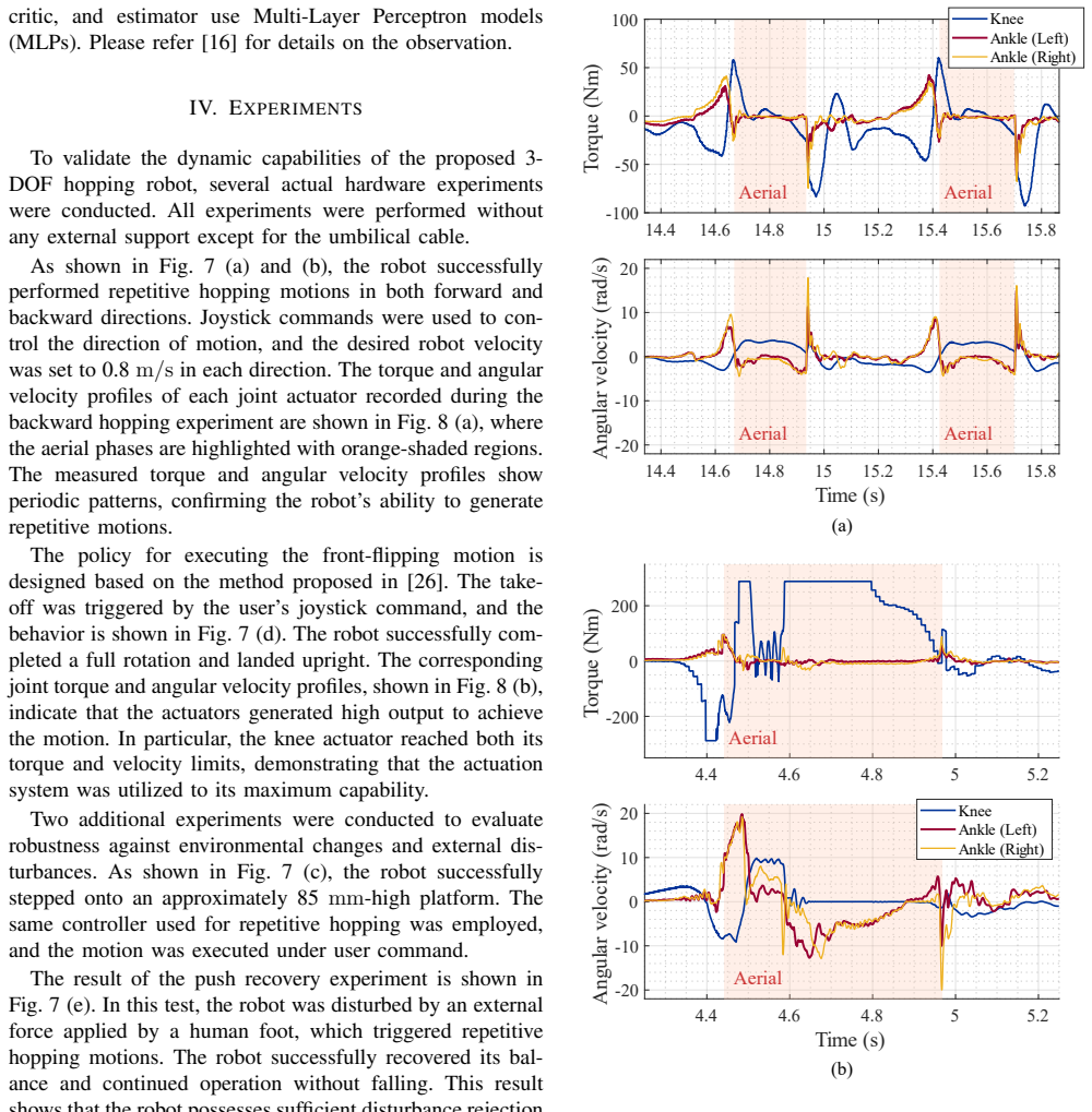
The paper's central claim is that dynamic, repetitive flat-foot hopping with a human-like leg layout is achievable on a 3-DOF prototype, and that this validates the hardware design as the foundation for a bipedal robot. In the authors' account, the knee actuator reaches a 320 N·m peak torque and a 20:1 reduction through a 3K compound planetary gearbox whose tooth counts ($Z_S = 44$, $Z_{P1} = 44$, $Z_{P2} = 32$, $Z_F = 132$, $Z_O = 120$) were selected by solving a mixed-integer nonlinear program that maximizes the hollow-shaft diameter for cable routing, minimizes mass, and enforces assembly, interference, and size constraints. The same custom-design approach extends to the motor drivers and the EtherCAT–CAN converter, which fit within the compact joint envelopes. On the control side, a reinforcement-learning policy trained in a simulation that models the closed-loop ankle linkage as a kinematic chain with a pin constraint transfers to the real robot without external support and produces the demonstrated behaviors: repetitive forward and backward hopping at 0.8 m/s, a complete front flip landing upright, an 85 mm step-up, and push recovery. The authors read these results as evidence that the actuators can deliver both the torque and the velocity that aggressive maneuvers demand, and that the platform can absorb the resulting impact loads.
Load-bearing premise
The entire actuator design rests on an unstated gear-ratio formula, Eq. (5): if that formula mis-models how the two planet gears and two ring gears interlock, the knee joint is not actually a 20:1 reducer and the hopping and flipping experiments do not validate the gearbox as designed.
Editorial extensions
If this is right
- The mixed-integer nonlinear gearbox-design procedure—ratio, assembly, interference, and size constraints over integer tooth counts—applies directly to the joints of the planned 13-DOF biped, which the authors state is being built on the same electrical architecture and gearbox methodology.
- The reinforcement-learned controller transfers from a simulation that explicitly models the closed-loop ankle, so the same training pipeline should extend to the more complex kinematics of a full leg without a new method.
- The knee actuator reaching both its torque and velocity limits during the front flip means the D151 is sized at the envelope for aggressive maneuvers, giving a measured operating point for specifying the biped's actuators.
- Flat-foot standing and push recovery are demonstrated on a single leg with a small support polygon; the biped's larger support polygon and second leg should make the same learned behaviors easier to maintain.
Reading between the lines
- A standalone check of the uncited ratio formula, Eq. (5), is the fastest way to confirm the gearbox claim independently: re-deriving it from standard compound-planetary kinematics and comparing with the published tooth counts takes a short calculation.
- Because the same controller handled an 85 mm step with no retraining, its terrain margin is probably larger than demonstrated; a sweep of increasing step height would quantify how much headroom the sim-to-real training left on the table.
- The experiments run tethered, so the onboard battery and the custom converter have not been stressed by repeated impacts; running the same motions on battery power would test whether the power and communication chain, not just the actuators, survives dynamic loads.
- A measured push-impulse limit for the single-leg policy would double as a lower-bound disturbance-rejection benchmark for the biped, since balancing on one flat foot is harder than on two.
Signed reviews
Editorial analysis
A structured set of objections, weighed in public.
Referee Report
Summary. The paper presents the design, fabrication, and experimental evaluation of a 12.45 kg, 3-DOF hopping robot with a flat foot and a human-like lower-limb layout (one knee DOF, two ankle DOFs), positioned as an intermediate platform toward a 13-DOF biped. The hardware contribution centers on a custom knee actuator (D151) containing a 20:1 3K compound planetary gearbox whose tooth counts (ZS=44, ZP1=44, ZP2=32, ZF=132, ZO=120) are selected by a mixed-integer nonlinear program with a hollow shaft for cable routing, plus custom motor drivers and an EtherCAT-CAN converter. The controller is a PPO-trained reinforcement-learning policy with barrier-based style rewards, trained in RaiSim with a closed-loop ankle model and deployed to hardware. Experiments demonstrate forward and backward hopping, an 85 mm step-up, a front flip, and push recovery, all with the robot tethered by an umbilical cable. The paper claims stable, repetitive hopping and concludes the platform is an effective intermediate testbed for bipedal robots.
Significance. If the claims are established, this is a useful contribution: the MINLP gear-tooth selection is concrete and the selected tooth counts verifiably satisfy the stated structural, assembly, and ratio equations, which is a strength; the hardware is real, and the periodic torque/velocity traces and video snapshots give external evidence that the system hops. I also confirmed that Eq. (5), though underived, is correct when derived from the Willis relation and constraints (2)-(3), so the gear-ratio concern raised by the companion stress-test does not land. However, the experimental evidence is anecdotal: there are no repeated-trial statistics, no quantitative performance metrics, and the umbilical cable's mechanical interaction is never measured or bounded. Because the paper's central claim is that the platform validates hardware for an untethered biped, these gaps are load-bearing. The strengths are real, but the validation standard needs to be raised.
major comments (3)
- [Section IV, first paragraph; Section V] Section IV states that all experiments were performed 'without any external support except for the umbilical cable,' but the cable's mechanical interaction is never quantified or bounded. During flight and touchdown, tension in a power/communication tether can exert vertical and lateral forces on the 12.45 kg body, potentially assisting balance, jump height, and flip landing. Since the stated purpose is to validate hardware for an untethered biped (Abstract and Section V), this is a load-bearing gap. Please add a cable-force measurement (e.g., a load cell at the anchor), a slack/tension analysis, or an explicit demonstration that cable forces are negligible relative to body weight (about 122 N) and the measured joint torques. If such data are not available, the conclusions must be correspondingly tempered.
- [Section IV, Figs. 7 and 8] The claims of 'repetitive hopping' and 'successfully completed a full rotation and landed upright' are supported by one snapshot sequence and one torque/velocity trace per behavior. There are no repeated-trial counts, success rates, or variability metrics such as hop height, hop period, aerial time, foot placement error, or landing success. A single successful demonstration does not establish repeatability or robustness. Please provide N repeated trials with quantitative summaries and, if failures occurred, report the failure rate.
- [Section II-D, Eq. (5)] Equation (5), the gear-ratio formula for the 3K compound planetary gearbox, is stated without derivation or citation. I re-derived it from the Willis relation together with the structural constraints (2) and (3) and found it to be correct, so this is not a correctness objection; however, the derivation should be included or a source cited, because the selected tooth counts and the claimed 20:1 ratio and knee torque all rest on this formula, and the formula is not obvious.
minor comments (6)
- [Abstract and Section II-A] The Abstract reports 840 mm as the fully extended length, while Section II-A reports 890 mm; these values should be made consistent.
- [Eq. (1)] The cost function in Eq. (1) contains Z_{P3}^2, but the optimization variables define only Z_{P1} and Z_{P2}; this should be Z_{P2} to be consistent with the rest of the paper.
- [Table II] Table II reports D151 rotor inertia as 'measured in the three-dimensional design software'; this is a CAD estimate, not a measurement, and should be labeled as such.
- [Section III] The controller description refers to [16] for the observation vector details; since [16] is a preprint, include a full list of observations and training hyperparameters for reproducibility.
- [Fig. 8] The claim that the knee actuator 'reached both its torque and velocity limits' is not verifiable from Fig. 8 because no limit lines or definitions of the limits are shown; please add them.
- [References] Reference [26] is an anonymous submission under review; the final version should resolve the attribution and status of this citation according to journal policy.
Circularity Check
No significant circularity: Eq. (5) is a derivable kinematic gear-ratio relation, the MINLP tooth selection is a design synthesis with the target ratio as an input, and the RL controller is validated against measured hardware outcomes rather than its own reward terms.
full rationale
Walking the paper's derivation chain, the load-bearing technical steps are the gearbox design and the learned controller, and neither reduces to its own inputs. The gear-ratio condition, Eq. (5), is stated as a constraint for the 3K compound planetary gearbox; although no derivation is shown in the paper, it is a kinematic relation of the same form used for compound planetary trains, and the selected tooth counts (ZS=44, ZP1=44, ZP2=32, ZF=132, ZO=120) are produced by an MINLP solver from the stated constraints. The target ratio of 20 is an input to the optimization, not a fitted output relabeled as a prediction, so the design process is not circular. The reinforcement-learning controller is trained in simulation using barrier rewards that encode the desired hopping style, but the paper's validation is the physical robot: measured torque and angular-velocity traces, repetitive forward/backward hopping, a front flip, step-up, and push recovery are all hardware outcomes that stand outside the training objective. The self-citations to [16] and [26] provide the control framework and flip-policy method, but the experimental success is not justified by those citations; it is justified by the reported hardware tests. The tethered-cable concern raised by the skeptical review is a threat to the validity of the hardware evidence because cable forces are never quantified, but that is an experimental confound, not a circular derivation. No equation or fitted parameter is shown to be equivalent by construction to a claimed prediction, so the circularity score is 0.
Assumptions & free parameters
free parameters (9)
- Target knee gear ratio G_target =
20
- Gear module M =
0.6
- Rotor inner diameter D =
79.4 mm
- Minimum carrier clearance alpha_min =
not reported
- Minimum tooth counts Z_S,min, Z_P1,min, Z_P2,min =
not reported
- Desired hopping frequency and foot clearance =
not reported
- Barrier reward weights gamma_i =
all equal, value not reported
- Command velocity for hopping experiments =
0.8 m/s
- Low-level PD gains =
not reported
assumptions (6)
- domain assumption The 3K gearbox ratio formula (Eq. 5) correctly models the fabricated gear kinematics.
- domain assumption Assembly feasibility conditions (Eq. 4) from [15] apply to this gearbox with n_P planets.
- domain assumption Meshing geometry equations Z_F = Z_S + 2 Z_P1 and Z_O = Z_S + Z_P1 + Z_P2 (Eqs. 2 and 3) hold.
- domain assumption RaiSim's pin-constraint modeling of the closed-loop ankle mechanism is faithful, and the simulated controller transfers to hardware.
- domain assumption The four-bar knee transmission is exactly 1:1 with negligible backlash and compliance.
- domain assumption The flat-foot support polygon is sufficient for stable one-legged standing and hopping within the joint ranges.
Cite this review
Pith. "Pith review of Design of a 3-DOF Hopping Robot with an Optimized Gearbox: An Intermediate Platform Toward Bipedal Robots." pith.science (2026). https://pith.science/paper/UF4BSQTB
@misc{pith2026250512231,
  author       = {Pith},
  title        = {Pith review of: Design of a 3-DOF Hopping Robot with an Optimized Gearbox: An Intermediate Platform Toward Bipedal Robots},
  year         = {2026},
  howpublished = {\url{https://pith.science/paper/UF4BSQTB}},
  note         = {Machine review of arXiv:2505.12231}
}
read the original abstract
This paper presents a 3-DOF hopping robot with a human-like lower-limb joint configuration and a flat foot, capable of performing dynamic and repetitive jumping motions. To achieve both high torque output and a large hollow shaft diameter for efficient cable routing, a compact 3K compound planetary gearbox was designed using mixed-integer nonlinear programming for gear tooth optimization. To meet performance requirements within the constrained joint geometry, all major components-including the actuator, motor driver, and communication interface-were custom-designed. The robot weighs 12.45 kg, including a dummy mass, and measures 840 mm in length when the knee joint is fully extended. A reinforcement learning-based controller was employed, and robot's performance was validated through hardware experiments, demonstrating stable and repetitive hopping motions in response to user inputs. These experimental results indicate that the platform serves as a solid foundation for future bipedal robot development.
Figures


Figures from the paper (5 more)


Reference graph
Works this paper leans on
-
[1]
Single-legged hopping robotics research—a review,
A. Sayyad, B. Seth, and P. Seshu, “Single-legged hopping robotics research—a review,” Robotica, vol. 25, no. 5, pp. 587–613, 2007
work page 2007
-
[2]
M. H. Raibert, Legged robots that balance . MIT press, 1986
1986
-
[3]
A new approach to the control of the planar one-legged hopper,
C. Franc ¸ois and C. Samson, “A new approach to the control of the planar one-legged hopper,” The International Journal of Robotics Research, vol. 17, no. 11, pp. 1150–1166, 1998
work page 1998
-
[4]
Single actuator control analysis of a planar 3dof hopping robot
N. Cherouvim and E. Papadopoulos, “Single actuator control analysis of a planar 3dof hopping robot.” in Robotics: Science and Systems , 2005, pp. 145–152
work page 2005
-
[5]
Controlled passive dynamic running experiments with the arl-monopod ii,
M. Ahmadi and M. Buehler, “Controlled passive dynamic running experiments with the arl-monopod ii,” IEEE Transactions on Robotics , vol. 22, no. 5, pp. 974–986, 2006
work page 2006
-
[6]
The actuator with mechanically adjustable series compliance,
J. W. Hurst, J. E. Chestnutt, and A. A. Rizzi, “The actuator with mechanically adjustable series compliance,” IEEE Transactions on Robotics, vol. 26, no. 4, pp. 597–606, 2010
work page 2010
-
[7]
J. An, X. Ma, C. H. D. Lo, W. Ng, X. Chu, and K. W. S. Au, “Design and experimental validation of a monopod robot with 3-dof morphable inertial tail for somersault,” IEEE/ASME Transactions on Mechatronics, vol. 27, no. 6, pp. 5072–5083, 2022
work page 2022
-
[8]
Development of a biologically inspired hopping robot-
S.-H. Hyon and T. Mita, “Development of a biologically inspired hopping robot-” kenken”,” in Proceedings 2002 IEEE International Conference on Robotics and Automation (Cat. No. 02CH37292) , vol. 4. IEEE, 2002, pp. 3984–3991
work page 2002
Show all 26 references
-
[9]
Stable one-legged hopping without feedback and with a point foot,
K. D. Mombaur, R. W. Longman, H. G. Bock, and J. P. Schloder, “Stable one-legged hopping without feedback and with a point foot,” in Proceedings 2002 IEEE International Conference on Robotics and Automation, vol. 4. IEEE, 2002, pp. 3978–3983
2002
-
[10]
Design principles for energy-efficient legged locomotion and implementation on the mit cheetah robot,
S. Seok, A. Wang, M. Y . Chuah, D. J. Hyun, J. Lee, D. M. Otten, J. H. Lang, and S. Kim, “Design principles for energy-efficient legged locomotion and implementation on the mit cheetah robot,” Ieee/asme transactions on mechatronics , vol. 20, no. 3, pp. 1117–1129, 2014
2014
-
[11]
Mit cheetah 3: Design and control of a robust, dynamic quadruped robot,
G. Bledt, M. J. Powell, B. Katz, J. Di Carlo, P. M. Wensing, and S. Kim, “Mit cheetah 3: Design and control of a robust, dynamic quadruped robot,” in 2018 IEEE/RSJ International Conference on Intelligent Robots and Systems (IROS) . IEEE, 2018, pp. 2245–2252
2018
-
[12]
High-speed bounding with the mit cheetah 2: Control design and experiments,
H.-W. Park, P. M. Wensing, and S. Kim, “High-speed bounding with the mit cheetah 2: Control design and experiments,” The International Journal of Robotics Research , vol. 36, no. 2, pp. 167–192, 2017
2017
-
[13]
Design of kaist hound, a quadruped robot platform for fast and efficient locomotion with mixed- integer nonlinear optimization of a gear train,
Y .-H. Shin, S. Hong, S. Woo, J. Choe, H. Son, G. Kim, J.-H. Kim, K. Lee, J. Hwangbo, and H.-W. Park, “Design of kaist hound, a quadruped robot platform for fast and efficient locomotion with mixed- integer nonlinear optimization of a gear train,” in 2022 International Confere...
2022
-
[14]
Design and control of the rapid legged platform gazelle,
H. Jeong, K. Lee, W. Kim, I. Lee, and J.-H. Oh, “Design and control of the rapid legged platform gazelle,” Mechatronics, vol. 66, p. 102319, 2020. [Online]. Available: https://www.sciencedirect.com/ science/article/pii/S0957415819301503
2020
-
[15]
Single planetary mechanism teeth matching conditions,
N. Zou, Y . Wei, S. Chang, and D. Zhou, “Single planetary mechanism teeth matching conditions,” in 2015 International Conference on Advanced Manufacturing and Industrial Application . Atlantis Press, 2015, pp. 42–45
2015
-
[16]
A learning framework for diverse legged robot locomotion using barrier-based style rewards,
G. Kim, Y .-H. Lee, and H.-W. Park, “A learning framework for diverse legged robot locomotion using barrier-based style rewards,” arXiv preprint arXiv:2409.15780, 2024
2024 arXiv
-
[17]
Baron: A general purpose global optimization software package,
N. V . Sahinidis, “Baron: A general purpose global optimization software package,” Journal of global optimization , vol. 8, pp. 201– 205, 1996
1996
-
[18]
Learning quadrupedal locomotion over challenging terrain,
J. Lee, J. Hwangbo, L. Wellhausen, V . Koltun, and M. Hutter, “Learning quadrupedal locomotion over challenging terrain,” Science robotics, vol. 5, no. 47, p. eabc5986, 2020
2020
-
[19]
Not only rewards but also constraints: Applications on legged robot locomotion,
Y . Kim, H. Oh, J. Lee, J. Choi, G. Ji, M. Jung, D. Youm, and J. Hwangbo, “Not only rewards but also constraints: Applications on legged robot locomotion,” IEEE Transactions on Robotics , 2024
2024
-
[20]
Robotkeyframing: Learning locomotion with high-level objec- tives via mixture of dense and sparse rewards,
F. Zargarbashi, J. Cheng, D. Kang, R. Sumner, and S. Coros, “Robotkeyframing: Learning locomotion with high-level objec- tives via mixture of dense and sparse rewards,” arXiv preprint arXiv:2407.11562, 2024
2024 arXiv
-
[21]
Proximal policy optimization algorithms,
J. Schulman, F. Wolski, P. Dhariwal, A. Radford, and O. Klimov, “Proximal policy optimization algorithms,” arXiv preprint arXiv:1707.06347, 2017
2017 arXiv
-
[22]
Per-contact iteration method for solving contact dynamics,
J. Hwangbo, J. Lee, and M. Hutter, “Per-contact iteration method for solving contact dynamics,” IEEE Robotics and Automation Letters , vol. 3, no. 2, pp. 895–902, 2018
2018
-
[23]
Concurrent training of a control policy and a state estimator for dynamic and robust legged locomotion,
G. Ji, J. Mun, H. Kim, and J. Hwangbo, “Concurrent training of a control policy and a state estimator for dynamic and robust legged locomotion,” IEEE Robotics and Automation Letters , vol. 7, no. 2, pp. 4630–4637, 2022
2022
-
[24]
Dreamwaq: Learning robust quadrupedal locomotion with implicit terrain imagination via deep reinforcement learning,
I. M. A. Nahrendra, B. Yu, and H. Myung, “Dreamwaq: Learning robust quadrupedal locomotion with implicit terrain imagination via deep reinforcement learning,” in 2023 IEEE International Conference on Robotics and Automation (ICRA) . IEEE, 2023, pp. 5078–5084
2023
-
[25]
Asymmetric actor critic for image-based robot learning,
L. Pinto, M. Andrychowicz, P. Welinder, W. Zaremba, and P. Abbeel, “Asymmetric actor critic for image-based robot learning,” arXiv preprint arXiv:1710.06542, 2017
2017 arXiv
-
[26]
Learning impact-rich rotational maneuvers via cen- troidal velocity rewards and sim-to-real techniques: A one-leg hop- per flip case study,
Anonymous, “Learning impact-rich rotational maneuvers via cen- troidal velocity rewards and sim-to-real techniques: A one-leg hop- per flip case study,” 2025, submitted to CoRL 2025 (Double-blind Review), under review
2025
Reviewed August 15, 2026 · model on record in the stance chip above.
Discussion (0). Continue with ORCID to comment.