REVIEW 4 major objections 6 minor 27 references
Capacity Enhancement Analysis and Implementation of a 3D Array Based on Miniaturized Dipole Antennas
T0 review · 4 major / 6 minor · reviewed 2026-08-07 · deepseek-v4-flash
Pith's one-line read The paper claims that a three-dimensional array of miniaturized dipole antennas can exceed the degrees-of-freedom limit of a planar MIMO array with the same physical aperture, and reports a 16% capacity gain at 20 dB SNR under a 3GPP…
desk verdict Real engineering content with a credible DoF story; the headline capacity gain is simulation-only at scale, but the measured single-row prototype supports the element-level claims. read the letter →
The pith
A machine-rendered reading of the paper's core claim, the machinery that carries it, and where it could break.
The reading
What carries the argument
The load-bearing object is the miniaturized dual-polarized dipole element (Element 2/3), whose small electrical size reduces the scattering and shadowing footprint of the upper layer so lower elements keep near-broadside patterns. The efficiency fix is resonant-mode merging: the lower element in the 3D array exhibits three resonances with wide frequency spacing, and the paper shortens the square ring and chamfered corners to raise mode 1 and extends split-ring and dipole-arm current paths to lower mode 3, pulling both toward mode 2 so the input impedance stays uniform and the lower elements remain matched. The DoF analysis is carried by the Kronecker covariance model (correlation matrix times an efficiency matrix), with the half-space DoF limit of Eq. (9) computed from the surface area of the smallest convex polyhedron enclosing the array; that bound is what the 3D array surpasses for a planar aperture, and it predicts the asymptotic 0.35 DoF gain per element.
What would settle it
Build and measure the full five-row Array 9 with its planar counterpart, extract the measured active element patterns, run them through the same QuaDRiGa 3GPP scenarios with the same per-user normalization, and check whether the 3D array still shows roughly 16% capacity gain at 20 dB SNR and whether measured element efficiencies stay near 70%.
Extended reading notes
Core claim
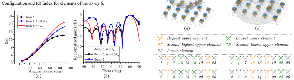
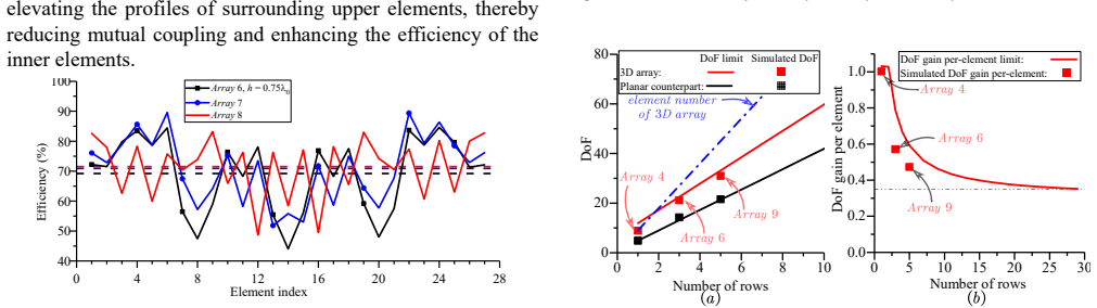
The paper's central claim is that appropriately arranged miniaturized elements make 3D arrays a practical way to break the aperture-limited capacity of planar MIMO arrays. A conventional crossed-dipole 3D array suffers severe lower-element pattern distortion (peak gain dropping from 8.7 dBi to 2.9 dBi) and efficiency collapse to 39%, so its DoF gain over the planar version is only 11.68%. Replacing the elements with miniaturized dipoles reduces the shielding effect; the central element's pattern is restored to broadside at 6.5 dBi and the array's DoF at 90 degrees angular spread rises 55.6% above the conventional 3D array, reaching 6.26 at 70 degrees, which exceeds the 6.14 half-space DoF limit of a planar array with the same $6.26\lambda_0^2$ aperture. Merging the lower element's three resonant modes by shrinking the square ring, chamfering corners, and extending split-ring current paths brings reflection coefficients below -10 dB over 770-880 MHz and all element efficiencies above 73%. A five-row version of the design (Array 9) is then analyzed under 3GPP urban-macro channels, where it shows 14-16% capacity gains over the planar 5x5 array at 20 dB SNR, and the paper derives asymptotic scaling values of about 70% average efficiency and 0.35 DoF gain per added element for large arrays.
Load-bearing premise
The headline 16% capacity gain is computed from simulated active element patterns of a five-row array (Array 9) that was never fabricated, with the channel matrix normalized per user according to [22]; if a physical five-row build behaves differently, or that normalization supplies gain a real system would not have, the central capacity claim does not stand.
Editorial extensions
If this is right
- A base station that keeps its footprint and element count can raise MIMO capacity by stacking a second layer of miniaturized elements rather than by densifying the planar grid.
- Because the DoF gain per element approaches about 0.35 and efficiency stabilizes near 70%, the design should remain useful as arrays grow to massive-MIMO scales, not just for small prototypes.
- Upper-element profile height and profile distribution become tunable knobs: higher profiles increase DoF at oblique angles, and a concave profile can smooth efficiency across inner elements.
- The measured one-row prototype (Array 4) validates the S-parameter and pattern behavior, so the remaining performance claims rest on scaling the same element design to more rows.
- The capacity advantage persists at low SNR (6% at 0 dB in the 2D-user case), meaning the gain comes partly from efficiency and beamforming, not only from extra spatial dimensions.
Reading between the lines
- If the per-user channel normalization of [22] is adopted in practice, the same 3D miniaturized-element approach may transfer to other frequency bands and element geometries, since the design principle is about reducing scattering footprint rather than about a specific resonant structure.
- The profile-distribution result suggests an optimization problem the paper does not solve: choose each upper element's height to maximize capacity for a given angular spread, rather than the two discrete hemisphere configurations tested.
- A direct experimental test would be to measure a full five-row Array 9 and compare its active-element efficiency and channel capacity against the simulated 16% figure; such a build would also reveal whether the column normalization assumption hides gain that a physical array cannot deliver.
- The same surface-area DoF argument could be extended to other non-planar base-station form factors such as cylindrical or hemispherical arrays, where miniaturized elements would face similar shadowing trade-offs.
Editorial analysis
A structured set of objections, weighed in public.
Referee Report
Summary. The paper proposes a three-dimensional (3D) base-station antenna array built from miniaturized dual-polarized dipole elements, with the aim of increasing communication degrees of freedom (DoF) and capacity over conventional planar arrays of the same physical aperture. The authors compare a conventional crossed-dipole 3D array (Array 2) with a miniaturized-element 3D array (Array 3), then introduce a resonantly tuned lower element (Element 3) to recover efficiency, resulting in Array 4. Array 4 is fabricated and measured; larger arrays (Array 6 and Array 9, with 3 and 5 rows) are simulated. The paper reports that Array 4 exceeds the half-space planar DoF limit (6.26 vs. 6.14), that large-scale arrays approach a per-element DoF gain of about 0.35 and efficiency near 70%, and that in a QuaDRiGa 3GPP urban-macro simulation the 5-row Array 9 achieves a 16% higher capacity than its planar counterpart at 20 dB SNR.
Significance. If the central claims hold, the work provides a practical route toward beating aperture-limited capacity in MIMO base stations, which would be a meaningful contribution to antenna-array design. The measured S-parameters and radiation patterns of Array 4, along with the clear progression from Array 2 to Array 4, are concrete strengths: they show that the miniaturized-element concept works in hardware at the single-row level. The DoF calculations are based on standard embedded-pattern formulas, and the scaling analysis gives a falsifiable asymptotic prediction (0.35 per-element DoF gain). However, the headline capacity advantage is produced entirely from simulated patterns of Array 9, with no hardware validation at the 5-row scale and no uncertainty quantification in the channel results. The capacity claim and the DoF-limit-exceeding claim are therefore not yet supported with the same confidence as the measured single-row results.
major comments (4)
- [Section V, Figs. 31–32] The 14–16% capacity gains are computed from full-wave simulated active radiation patterns of Array 9 (45 ports, 5 rows), while only the 9-port single-row Array 4 was fabricated and measured (Section III.C). The scaling from one row to five rows is not a small extrapolation: Fig. 27 shows an average efficiency drop of roughly 11% from Array 4 to Array 6 and a further 5% to Array 9, and the active patterns, mutual coupling, and ground-plane effects of a real 5-row build are unverified. As it stands, the central quantitative claim rests on simulation-only hardware. I recommend either providing measured validation of at least a 3-row array or clearly stating in the abstract and conclusion that the capacity result is a simulation-based prediction, with the limitations of that prediction quantified.
- [Section V, Eq. (12)] The channel matrix is normalized per user by adjusting column-vector moduli according to the array's realized gain in the user's direction, following reference [22]. This normalization can redistribute gain between the 3D and planar arrays in a way that depends on the normalization convention; if the realized gain of the simulated Array 9 differs from a physical build, the per-user normalization could bias the capacity comparison. The manuscript does not state whether the same normalization is applied identically to both arrays, nor does it provide a sensitivity test. I request an explicit description of the normalization in Eq. (12), a justification that it preserves a physically meaningful comparison, and a check with an alternative normalization (e.g., fixed total radiated power or equal average channel gain).
- [Section V, Figs. 31–32] The capacity curves are point estimates without error bars, confidence intervals, or the number of Monte Carlo channel realizations. QuaDRiGa generates random user positions and channel realizations, so the reported 14%, 16%, and 23% differences could be within statistical fluctuation. The paper should report the number of independent trials, the variance across trials, and a statistical significance statement (e.g., mean and standard deviation, or box plots) for at least the key operating points at 20 dB SNR in Cases I and II.
- [Section III.A and Fig. 28] The claim that Array 3 'exceeds the half-space DoF limit of a planar array' rests on a difference of only 6.26 vs. 6.14 (about 2%). This margin is small enough that it could be affected by numerical discretization, the choice of angular spread, or the exact definition of the aperture area. The manuscript should state the numerical precision of the DoF computation, show how the half-space limit is obtained from the aperture area, and explain why a 2% excess is physically meaningful rather than numerical. Relatedly, the theoretical 'DoF gain per-element limit' curve in Fig. 28(b) is asserted without derivation; the source or derivation of this upper bound should be provided.
minor comments (6)
- [Abstract] The symbol '6.26 λ02' should be '6.26 λ0²' or '6.26 λ0^2'; as printed, the superscript is unclear.
- [Figs. 3, 10, 12, 14, 15, 17, 29 and captions] There are several typographical errors: 'Thata' should be 'Theta', 'Imput impedance' should be 'Input impedance', 'Arraay' should be 'Array', 'coefficent' should be 'coefficient', and 'typology' should be 'topology' in Fig. 29.
- [Section IV.A, Fig. 21(b)] The term 'renormalized radiation patterns' is not defined. State how the patterns are normalized and whether the comparison at 60° scan is based on realized gain or directivity.
- [Section III.C, Fig. 19] The measured radiation patterns are only shown for φ=0° and φ=90° planes. Since the array is 3D and asymmetric, please state whether the omitted planes are verified by simulation or whether the measurement is sufficient for the claimed DoF/correlation analysis.
- [References] Reference [22] is listed with page range 'pp. 1–1'; update to the final pagination or early-access DOI if still in press.
- [Section V, Figs. 31–32] The legend labels '5×5 Planar array' should be made consistent with the text: Array 9 is described as a 5-row array, and the planar counterpart's exact port count and geometry should be specified in the caption.
Circularity Check
No circular derivation: the cited 3D topology, miniaturized element, and channel normalization are inputs rather than re-labeled outputs, and the DoF and capacity results come from full-wave simulation and the external QuaDRiGa channel model.
full rationale
The paper's derivation chain is not circular. The 3D-array premise is attributed to the authors' own prior work [13], the miniaturized element and lower-element resonance adjustments follow [20], and the channel matrix normalization follows [22]; these are design and method inputs, not quantities that the paper claims to derive. The DoF values are computed from simulated embedded radiation patterns using the standard Kronecker covariance model (Eqs. 1–8) and are compared with an independent DoF-limit formula from [21] and with measured S-parameters and patterns of Array 4. The headline 16% capacity gain is obtained by feeding simulated active radiation patterns of Array 9 into the external QuaDRiGa 3GPP UMa model in Section V, not by algebraic rearrangement of the cited inputs. The asymptotic DoF-gain-per-element value near 0.35 is presented as an extrapolation from the theoretical DoF-limit ratio for the array geometry, not as a fitted parameter that equals an input by construction. The absence of a fabricated five-row Array 9 is a validation risk for the central quantitative claim, but it is not circularity: the claim is a simulation-based prediction, not a restatement of the inputs. Accordingly, the paper has no self-consistent reduction of a predicted result to its own defining assumption, and the score is 0.
Assumptions & free parameters
free parameters (4)
- Upper element profile height h =
0.5λ0, λ0, 0.75λ0
- Crossed polarization discrimination κ =
1
- Element 3 tuning geometry =
not disclosed
- Inter-element and row spacing =
0.5λ0
assumptions (6)
- domain assumption Angular power spectrum is uniformly distributed within the angular spread
- domain assumption Covariance factors as R = Φ ⊙ Ξ
- standard math Surface-area DoF limit formula from [21]
- domain assumption Channel matrix column normalization per user [22]
- domain assumption QuaDRiGa 3GPP UMa scenario is representative of realistic deployment
- domain assumption Simulated radiation patterns predict fabricated behavior
Cite this review
Pith. "Pith review of Capacity Enhancement Analysis and Implementation of a 3D Array Based on Miniaturized Dipole Antennas." pith.science (2026). https://pith.science/paper/KC227CBE
@misc{pith2026250518506,
  author       = {Pith},
  title        = {Pith review of: Capacity Enhancement Analysis and Implementation of a 3D Array Based on Miniaturized Dipole Antennas},
  year         = {2026},
  howpublished = {\url{https://pith.science/paper/KC227CBE}},
  note         = {Machine review of arXiv:2505.18506}
}
read the original abstract
Theoretically, the three-dimensional (3D) array architecture provides a higher communication degree of freedom (DoF) compared to the planar arrays, allowing for greater capacity potential in multiple-input multiple-output (MIMO) systems. However, in practical implementations, the upper elements of 3D arrays significantly degrade the performance of the lower elements, leading to increased inter-element correlation and reduced array efficiency. As a result, the expected enhancement in MIMO performance is often suboptimal. To address this issue, this work employs a miniaturized antenna element to reduce the inter-element correlation and thus enhance the DoF of the 3D array. Moreover, to mitigate the efficiency degradation of the lower elements caused by the upper ones, the structures of lower elements are modified to achieve wideband impedance matching. The influence of upper element profile distribution on DoF and element efficiency is investigated, and the scalability of the proposed 3D array is theoretically analyzed. Finally, the MIMO performance of the proposed 3D array is evaluated under 3GPP scenarios, demonstrating a 16% higher capacity than conventional 2D arrays under the same SNR of 20 dB and a physical aperture area of 6.26 {\lambda}02. These results indicate that 3D arrays of appropriately arranged miniaturized elements offer a promising approach to enhancing MIMO system performance.
Figures


Figures from the paper (18 more)






Reference graph
Works this paper leans on
-
[22]
Performance Analysis of Large Multiuser MIMO Systems With Space-Constrained 2-D Antenna Arrays,
S. Biswas, C. Masouros, and T. Ratnarajah, “Performance Analysis of Large Multiuser MIMO Systems With Space-Constrained 2-D Antenna Arrays,” IEEE Trans. Wirel. Commun., vol. 15, no. 5, pp. 3492–3505, May 2016, doi: 10.1109/TWC.2016.2522419
-
[1]
Geometrical-Based Modeling for Millimeter-Wave MIMO Mobile-to-Mobile Channels,
R. He, B. Ai, G. L. Stuber, G. Wang, and Z. Zhong, “Geometrical-Based Modeling for Millimeter-Wave MIMO Mobile-to-Mobile Channels,” IEEE Trans. Veh. Technol. , vol. 67, no. 4, pp. 2848–2863, Apr. 2018, doi: 10.1109/TVT.2017.2774808
arXiv 2018
-
[2]
These results indicate that 3D arrays of appropriately arranged miniaturized elements offer a promising approach to enhancing MIMO system performance. Index Terms —Antenna efficiency, Channel capacity, DoF, Miniaturized elements, Multiple-input-multiple-output (MIMO) communications, 3D array architecture. This work was supported in part by the National Na...
-
[3]
As observed, the reflection coefficient of the lower elements in Array 2 deteriorates to above -6 dB, while the isolation between elements decreases to approximately 10 dB. These results suggest that the presence of upper elements alters the radiating environment of the lower elements, leading to impedance mismatch. Additionally, part of the energy radiat...
-
[4]
Especially, at θ=90°, the DoF of Array 3 is 55.6% higher than that of Array 2. Moreover, the half-space DoF limit of a planar array with the same physical aperture size as Array 3 is 6.14 at 825 MHz, while the DoF of Array 3 reaches 6.26 at θ=70°, confirming the feasibility of using a 3D array architecture to surpass the DoF limit of planar arrays. Howeve...
-
[5]
As observed, Array 4 exhibits a notable beamforming gain improvement of more than 3 dB over Array 2. Moreover, the theoretical gain limit of a planar array is given by [3], where Ae is the effective aperture area at broadside. It is observed that the gain of Array 4 at a 60° scan angle exceeds this limit, confirming that the 3D array composed of miniaturi...
-
[6]
User terminals are equipped with omnidirectional, single-polarized antennas
and its planar counterpart are used as the transmit arrays. User terminals are equipped with omnidirectional, single-polarized antennas. MMSE precoding is assumed, and the capacity of each user is individually computed using (11) where (12) is the channel matrix with a dimension of MN-by-U between the user locating at ru and the antenna locating at rm,n. ...
-
[7]
D. Tse and P. Viswanath, Fundamentals of Wireless Communication , 1st ed. Cambridge University Press, 2005. doi: 10.1017/CBO9780511807213
Show all 27 references
-
[8]
The element-gain paradox for a phased-array antenna,
P. Hannan, “The element-gain paradox for a phased-array antenna,” IEEE Trans. Antennas Propag. , vol. 12, no. 4, pp. 423–433, Jul. 1964, doi: 10.1109/TAP.1964.1138237
1964
-
[9]
Degrees of Freedom of Holographic MIMO Channels,
A. Pizzo, T. L. Marzetta, and L. Sanguinetti, “Degrees of Freedom of Holographic MIMO Channels,” in 2020 IEEE 21st International Workshop on Signal Processing Advances in Wireless Communications (SP AWC) , Atlanta, GA, USA: IEEE, May 2020, pp. 1–5. doi: 10.1109/SPAWC48557.2020.9154219
2020
-
[10]
Dual-Pola rized Wide-Angle Scanning Phased Array Antenna for 5G Communication Systems,
G. Yang and S. Zhang, “Dual-Pola rized Wide-Angle Scanning Phased Array Antenna for 5G Communication Systems,” IEEE Trans. Antennas Propag., vol. 70, no. 9, pp. 7427–7438, Sep. 2022, doi: 10.1109/TAP.2022.3141188
2022
-
[11]
Broadband Decoupling for Antenna Arrays Using Multiple Decoupling Nulls,
J. Jiang and Q.-X. Chu, “Broadband Decoupling for Antenna Arrays Using Multiple Decoupling Nulls,” IEEE Trans. Antennas Propag. , vol. 71, no. 11, pp. 8616–8627, Nov. 2023, doi: 10.1109/TAP.2023.3312821
2023
-
[12]
Multiband and Wideband Self-Multipath Decoupled Antenna Pairs,
A. Zhang, K. Wei, and Z. Zhang, “Multiband and Wideband Self-Multipath Decoupled Antenna Pairs,” IEEE Trans. Antennas Propag. , vol. 71, no. 7, pp. 5605–5615, Jul. 2023, doi: 10.1109/TAP.2023.3267177
2023
-
[13]
Wideband MIMO Antennas With Enhanced Isolation Using Coupled CPW Transmission Lines,
Z. Zhou, Y . Ge, J. Yuan, Z. Xu, and Z. D. Chen, “Wideband MIMO Antennas With Enhanced Isolation Using Coupled CPW Transmission Lines,” IEEE Trans. Antennas Propag., vol. 71, no. 2, pp. 1414–1423, Feb. 2023, doi: 10.1109/TAP.2022.3232693
2023
-
[14]
QuaDRiGa: A 3-D Multi-Cell Channel Model With Time Evolution for Enabling Virtual Field Trials,
S. Jaeckel, L. Raschkowski, K. Borner, and L. Thiele, “QuaDRiGa: A 3-D Multi-Cell Channel Model With Time Evolution for Enabling Virtual Field Trials,” IEEE Trans. Antennas Propag., vol. 62, no. 6, pp. 3242–3256, Jun. 2014, doi: 10.1109/TAP.2014.2310220
2014
-
[15]
Reducing Correlation in Compact Arrays by Adjusting Near-Field Phase Distribution for MIMO Applications,
M. Li, X. Chen, A. Zhang, A. A. Kishk, and W . Fan, “Reducing Correlation in Compact Arrays by Adjusting Near-Field Phase Distribution for MIMO Applications,” IEEE Trans. Veh. Technol. , vol. 70, no. 8, pp. 7885–7896, Aug. 2021, doi: 10.1109/TVT.2021.3094314
2021
-
[16]
Simultaneous Decoupling and Decorrelation Scheme of MIMO Arrays,
X. Chen et al. , “Simultaneous Decoupling and Decorrelation Scheme of MIMO Arrays,” IEEE Trans. Veh. Technol., vol. 71, no. 2, pp. 2164–2169, Feb. 2022, doi: 10.1109/TVT.2021.3134180
2022
-
[17]
Improvement of Diversity and Capacity of MIMO System Using Scatterer Array,
Y . Wang et al., “Improvement of Diversity and Capacity of MIMO System Using Scatterer Array,” IEEE Trans. Antennas Propag., vol. 70, no. 1, pp. 789–794, Jan. 2022, doi: 10.1109/TAP.2021.3098568. 5 1 01 52 02 53 03 54 04 56.2 6.4 6.6 6.8 7.0 7.2 7.4 Capacity (bit/s/Hz) User nu...
2022
-
[18]
Breaking the Degrees-of-Freedom Limit of Holographic MIMO Communications: A 3-D Antenna Array Topology,
S. S. A. Y uan et al. , “Breaking the Degrees-of-Freedom Limit of Holographic MIMO Communications: A 3-D Antenna Array Topology,” IEEE Trans. Veh. Technol. , vol. 73, no. 8, pp. 11276–11288, Aug. 2024, doi: 10.1109/TVT.2024.3372704
2024
-
[19]
Horse (Electromagnetics) is More Important Than Horseman (Information) for Wireless Transmission,
M. D. Migliore, “Horse (Electromagnetics) is More Important Than Horseman (Information) for Wireless Transmission,” IEEE Trans. Antennas Propag. , vol. 67, no. 4, pp. 2046–2055, Apr. 2019, doi: 10.1109/TAP.2018.2889158
2019
-
[20]
MRC Diversity and MIMO Capacity Evaluations of Multi-Port Antennas Using Reverberation Chamber and Anechoic Chamber,
X. Chen, P.-S. Kildal, J. Carlsson, and J. Yang, “MRC Diversity and MIMO Capacity Evaluations of Multi-Port Antennas Using Reverberation Chamber and Anechoic Chamber,” IEEE Trans. Antennas Propag., vol. 61, no. 2, pp. 917–926, Feb. 2013, doi: 10.1109/TAP.2012.2223442
2013
-
[21]
Correlation and capacity of MIMO systems and mutual coupling, radiation efficiency, and diversity gain of their antennas: simulations and measurements in a reverberation chamber,
P.-S. Kildal and K. Rosengren, “Correlation and capacity of MIMO systems and mutual coupling, radiation efficiency, and diversity gain of their antennas: simulations and measurements in a reverberation chamber,” IEEE Commun. Mag. , vol. 42, no. 12, pp. 104–112, Dec. 2004, doi:...
2004 arXiv
-
[23]
Angle-of-arrival statistics for low resolution antennas,
J. B. Andersen and K. I. Pedersen, “Angle-of-arrival statistics for low resolution antennas,” IEEE Trans. Antennas Propag. , vol. 50, no. 3, pp. 391–395, Mar. 2002, doi: 10.1109/8.999632
2002 doi
-
[24]
Diversity and Correlation in Rayleigh Fading MIMO Channels,
M. T. Ivrlac and J. A. No ssek, “Diversity and Correlation in Rayleigh Fading MIMO Channels,” in 2005 IEEE 61st Vehicular Technology Conference, Stockholm, Sweden: IEEE, 2005, pp. 151–155. doi: 10.1109/VETECS.2005.1543268
2005
-
[25]
Miniaturized Broadband Dual-Polarized Dipole Antenna Based on Multiple Resonances and its Array for Base-Station Applications,
W. Yang, Y . Li, Q. Xue, S. Liao, and W. Che, “Miniaturized Broadband Dual-Polarized Dipole Antenna Based on Multiple Resonances and its Array for Base-Station Applications,” IEEE Trans. Antennas Propag., vol. 70, no. 11, pp. 11188–11193, Nov. 2022, doi: 10.1109/TAP.2022.3209273
2022
-
[26]
Degrees of Freedom and Characteristic Modes: Estimates for radiating and arbitrarily shaped objects,
M. Gustafsson and J. Lundgren, “Degrees of Freedom and Characteristic Modes: Estimates for radiating and arbitrarily shaped objects,” IEEE Antennas Propag. Mag. , vol. 66, no. 6, pp. 18–28, Dec. 2024, doi: 10.1109/MAP.2024.3389451
2024
-
[27]
Electromagnetic Normalization of Channel Matrix for Holographic MIMO Communications,
S. S. A. Y uan, L. Wei, X. Chen, C. Huang, and W. E. I. Sha, “Electromagnetic Normalization of Channel Matrix for Holographic MIMO Communications,” IEEE Trans. Wirel. Commun. , pp. 1–1, 2025, doi: 10.1109/TWC.2025.3543585
2025
Reviewed August 7, 2026 · model on record in the stance chip above.
Discussion (0). Continue with ORCID to comment.