REVIEW 4 major objections 5 minor 1 cited by
OFDMA for Pinching Antenna Systems
T0 review · 4 major / 5 minor · reviewed 2026-08-07 · deepseek-v4-flash
Pith's one-line read A fixed multi-pinching-antenna downlink is a frequency-selective FIR channel, and OFDMA with greedy subcarrier assignment and water-filling raises the worst user's data rate well above single-carrier scheduling.
desk verdict First clean OFDMA treatment of fixed multi-pinching-antenna downlinks, with real simulation gains, but the headline numbers rest on an unverified equal-amplitude waveguide model. read the letter →
The pith
A machine-rendered reading of the paper's core claim, the machinery that carries it, and where it could break.
The reading
What carries the argument
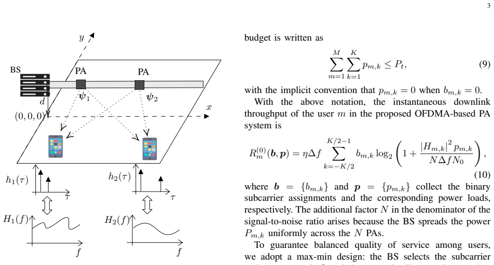
The load-bearing object is the FIR channel model in Eq. (4) and its Fourier transform in Eq. (7), in which the $n$-th tap has amplitude $h_{0,n}h_{m,n}$, where $h_{0,n}$ is a unit-magnitude phase from the waveguide feed to the $n$-th aperture and $h_{m,n}$ is the free-space path from that aperture to user $m$, located at the composite delay $\tau_{m,n} = \|\psi_m-\psi_P^n\|/(\lambda f_c) + \|\psi_0-\psi_P^n\|/(\lambda_g f_c)$. These taps are what make the channel frequency-selective and set the cyclic-prefix length (from the worst excess delay) and the FFT size (from the RMS delay spread via the coherence-bandwidth rule of thumb). The framework then rides on the OFDMA formulation in problem (P1), a max-min mixed-integer program whose binary subcarrier variables make it NP-hard, and on the two-stage heuristic--greedy subcarrier assignment maximizing $\Gamma_{m,k}=|H_{m,k}|^2/\max_{q\neq m}|H_{q,k}|^2$ for the least-served user, then classical water-filling per user--that keeps polynomial complexity while exploiting the ripples.
What would settle it
Measure the magnitude of the frequency response $|H_m(f)|$ on a real 30 m leaky waveguide with $N$ evenly spaced pinch points at 28 GHz and compare the measured tap amplitudes and coherence bandwidth with Eq. (7); if the taps are unequal because of waveguide loss or coupling variation, the predicted OFDMA-over-TDMA minimum-rate gap should narrow with $N$, and the simulation curves would not be reproduced.
Extended reading notes
Core claim
The central discovery is that a fixed, uniformly placed multi-pinching-antenna downlink has an unavoidable, strongly frequency-selective channel: the impulse response $h_m(\tau)$ in Eq. (4) is a sum of $N$ delayed replicas, each combining a guided delay through the waveguide and a free-space delay, and the transfer function $H_m(f)$ in Eq. (7) shows corresponding spectral ripples. With apertures meters apart, the composite delay spread is tens of nanoseconds, versus a 2 ns symbol at 500 MHz, so single-carrier reception without long guard intervals collapses under inter-symbol interference. The paper shows that OFDMA converts the ripples into usable frequency diversity: after choosing the cyclic prefix from the worst-case excess delay and the FFT window from the RMS delay spread, a two-stage allocation--greedy assignment of subcarriers to the currently lowest-rate user using the ratio $\Gamma_{m,k} = |H_{m,k}|^2 / \max_{q\neq m}|H_{q,k}|^2$, followed by per-user water-filling--approximately maximizes the minimum user rate. Simulations for a 30 m by 10 m room at 28 GHz with two or four users and low or moderate blockage show the OFDMA minimum rate consistently above the TDMA with single-carrier frequency-domain equalization and above a single centered PA.
Load-bearing premise
The results assume the waveguide delivers an equal-amplitude, phase-shifted copy of the signal to every pinch point and the base station spreads each subcarrier's power uniformly across all $N$ apertures; a real waveguide's attenuation or position-dependent coupling would break the equal-tap channel and could shrink the OFDMA advantage.
Editorial extensions
If this is right
- Fixed PA placements can serve multiple users without repositioning or tracking, because the OFDMA frame absorbs the multipath instead of avoiding it.
- Minimum user rate improves with the number of PAs under OFDMA, whereas the TDMA equalizer's effective SNR degrades as more taps add inter-symbol interference.
- The scheme remains useful under moderate LoS blockage, where a single centered PA nearly flattens in performance.
- System design parameters--cyclic prefix, subcarrier count, and FFT length--follow directly from measurable delays, giving a concrete OFDM frame-construction recipe for PA deployments.
- OFDMA's joint subcarrier and power control is the mechanism for fairness; the greedy allocation approaches the max-min optimum at polynomial cost.
Reading between the lines
- Editorial inference: the equal-tap waveguide model is the part a hardware team would test first; if real leaky waveguides attenuate the traveling wave, the FIR taps become unequal and the reported OFDMA gains are an upper bound, though the general FIR-plus-OFDMA method would still apply.
- Editorial inference: the same reasoning transfers to the uplink and to sub-6 GHz or lower-cost emulations; at lower carrier frequencies the physical aperture delays shrink relative to the symbol, so the frequency-selective effect and the OFDMA advantage should be smaller but measurable.
- Editorial inference: the max-min greedy rule could be extended to jointly optimize PA positions, which the paper lists as future work; a testable prediction is that such joint placement gives diminishing returns once the cyclic prefix covers the worst-case delay spread.
- Editorial inference: a direct rate-versus-$N$ experiment in a real 28 GHz waveguide would isolate the model's signature--OFDMA minimum rate rising with $N$--from other effects such as blockage, because the predicted slope is specific to the equal-amplitude FIR assumption.
Editorial analysis
A structured set of objections, weighed in public.
Referee Report
Summary. The paper considers a downlink from a base station feeding a leaky waveguide with N fixed pinching antennas to M single-antenna users. The authors model the resulting channel as an N-tap finite impulse response filter (Eq. 4), characterize its frequency selectivity, and propose an OFDMA framework with cyclic-prefix and FFT sizing. They formulate a max-min rate-fairness problem (P1) and solve it with a two-stage heuristic: greedy subcarrier assignment followed by per-user water-filling (Algorithm 1). Simulations compare the proposed scheme against TDMA with single-carrier frequency-domain equalization and against a single-PA baseline, reporting higher minimum user rates across various N, M, blockage, and power settings.
Significance. If the channel model is accepted, the paper gives a clear, low-complexity solution to the ISI problem that arises when fixed, spatially separated PAs serve multiple users, and it demonstrates the value of frequency diversity in PA systems. The derivation from geometry to Eq. (7) is explicit, the problem formulation is standard, and Algorithm 1 is easy to implement. However, the numerical gains rest on two unverified hardware idealizations: unit-magnitude waveguide taps and a uniform 1/N power split. The 'near-optimal' fairness claim is also not benchmarked against an optimal solver or an upper bound. These issues make the qualitative idea credible but the quantitative claims conditional.
major comments (4)
- [II, Eq. (3); III, Eq. (10)] The channel model assumes that the waveguide contribution h_{0,n} is a unit-magnitude phase and that the BS spreads each subcarrier's power uniformly across the N PAs, producing the factor 1/N in the SNR denominator of Eq. (10). A physical leaky waveguide radiates a fraction of the guided power at each aperture, so the tap amplitudes in Eq. (4) should generally decrease with distance from the feed; no measurement, coupling model, or citation is given for equal-amplitude taps. Since the CP length, coherence bandwidth, and the rate comparisons in Figs. 2-3 all depend on these tap amplitudes, the headline gain over TDMA is not yet tied to a physical implementation. Please add a waveguide attenuation/coupling model and re-evaluate the results, or justify equal amplitudes with a measurement.
- [Abstract; III, P1 and Algorithm 1] The claim that Algorithm 1 achieves 'near-optimal' max-min fairness is not supported. P1 is an NP-hard mixed-integer nonlinear program, and the paper provides no comparison with an optimal solver for small problem sizes, no upper bound from a relaxation, and no approximation guarantee. I recommend adding an exhaustive-search comparison for small values of K and M, or a relaxation-based upper bound, to quantify the optimality gap before using the phrase 'near-optimal'.
- [III, CP/FFT sizing paragraph] The chosen CP/FFT parameters are not mutually consistent with OFDM orthogonality. The paper sets T_FFT = T_CP + 1/B_c and then chooses K = 2^{floor(log2(B T_FFT))}, so that Delta_f = B/K. For standard OFDM, Delta_f must equal 1/T_FFT, which holds only if K = B T_FFT exactly; with the floor operation this is generally false. The inconsistency affects the efficiency factor eta = T_FFT/(T_FFT+T_CP) and the numerical rate results. Please redefine the design so that T_FFT = K/B (or Delta_f = 1/T_FFT) and update the simulations accordingly.
- [III, Algorithm 1, Stage 2] The per-user water-filling with a fixed budget P_t/M does not necessarily solve the max-min problem P1. The greedy stage assigns subcarriers based on provisional rates computed with equal power per subcarrier, but after stage 2 the actual user rates depend on the final power allocation, which can change the ordering of users; no guarantee or final max-min check is provided. Either the algorithm should be modified to iterate between assignment and power allocation, or the claim should be weakened to a heuristic that improves fairness rather than achieving near-optimal max-min fairness.
minor comments (5)
- [II, Eq. (4) and following text] The composite delay tau_{m,n} is used implicitly in Eq. (4) but only defined later in the CP/FFT paragraph; please define it before first use.
- [III, text after Eq. (8)] The phrase 'the m-th use' should be corrected to 'the m-th user'.
- [III, CP/FFT sizing paragraph] The formula K = 2^{floor(log2(B T_FFT))} selects the largest power of two not exceeding B T_FFT, not the 'next power of two'; please reword to avoid ambiguity.
- [IV, Fig. 2 caption] The caption 'Minimum data rate versus number of PA' should read 'number of PAs'.
- [III, Eq. (10) and surrounding text] The notation for the power variable is introduced as p_{m,k} in Eq. (9) but the sentence before Eq. (10) refers to P_{m,k}; please unify the notation.
Circularity Check
No significant circularity: the channel and OFDMA rate equations are constructed from geometry and standard OFDM principles; the same-group citations are contextual, not load-bearing.
full rationale
The paper's derivation chain is self-contained rather than circular. The FIR channel in Eq. (4) is built directly from the free-space path-loss model (1), the guided-wave phase (3), and the LoS blockage indicator (2). No parameter is fitted to the reported rate results, and the OFDMA design quantities (T_CP, T_FFT, K, Delta_f, and the rate expression in Eq. (10)) follow from the geometric delays by textbook OFDM rules. The max-min problem (P1) is a standard formulation solved with a greedy subcarrier assignment and water-filling, and the numerical gains are computed against TDMA and single-PA baselines defined in Eqs. (11)-(12) using the same channel model, so the comparison is an internal consistency check rather than a prediction forced by a fitted constant. The paper does cite prior works by overlapping authors, notably [9] for system parameters and [7] for coverage-probability context, but these citations are not load-bearing: the central OFDMA claim does not reduce to an unverified result imported from those papers. The main caveat is physical, not circular: Eq. (3) assumes unit-magnitude phase-only waveguide taps and Eq. (10) assumes a uniform 1/N power split across PAs, and real leaky-waveguide attenuation or nonuniform pinch coupling could alter the delay-spread profile and shrink the reported gains. This is a correctness or robustness risk about an idealized hardware model, not a circularity in the reasoning.
Assumptions & free parameters
free parameters (2)
- Coherence-bandwidth rule factor 5 in B_c about 1/(5 sigma_tau) =
5 (rule of thumb)
- Per-user power budget P_t/M in stage 2 of Algorithm 1 =
P_t/M
assumptions (5)
- domain assumption Each PA radiates a phase-shifted replica of the signal fed into the waveguide with no amplitude change along the guide (h_{0,n} in Eq. 3 is unit-magnitude).
- domain assumption The effective refractive index n_e is constant across the operating band (Section II).
- domain assumption LoS blockage probability is modeled as e^(-beta d) with beta from [10] (Section II).
- ad hoc to paper Each subcarrier's power is spread uniformly across the N PAs, giving the factor N in the SNR denominator of Eq. (10).
- standard math A cyclic prefix longer than the maximum delay spread with OFDMA orthogonality removes ISI and inter-user interference (Section III).
Cite this review
Pith. "Pith review of OFDMA for Pinching Antenna Systems." pith.science (2026). https://pith.science/paper/YDTZCPIF
@misc{pith2026250519902,
  author       = {Pith},
  title        = {Pith review of: OFDMA for Pinching Antenna Systems},
  year         = {2026},
  howpublished = {\url{https://pith.science/paper/YDTZCPIF}},
  note         = {Machine review of arXiv:2505.19902}
}
read the original abstract
Pinching-antenna (PA) systems route millimeter wave (mmWave) signals through a leaky waveguide and radiate them at "pinch" apertures, offering low-cost line-of-sight (LoS) coverage. However, when multiple PAs serve multiple users simultaneously, the downlink channel becomes strongly frequency-selective, creating inter-symbol interference (ISI) that existing single-carrier designs overlook. This paper models the overall channel as a finite impulse response (FIR) filter, characterizes its frequency selectivity, and explicitly accounts for the resulting ISI. To overcome ISI, we introduce an orthogonal frequency-division multiple access (OFDMA)-based framework and formulate a max-min resource-allocation problem to achieve user fairness. A lightweight two-stage heuristic-greedy subcarrier assignment, followed by per-user water-filling, achieves near-optimal fairness with polynomial complexity. Simulation results for an indoor layout demonstrate that the proposed scheme notably increases the minimum user rate compared to time-division single-carrier baselines and remains robust under moderate LoS blockage.
Figures


Forward citations
Cited by 1 Pith paper
-
Beamforming Design for Pinching Antenna Systems with Multiple Receive Antennas
A two-layer placement algorithm for pinching antennas that aligns signals across multiple receive antennas improves rate over single-antenna-oriented schemes, especially at close range.
Reference graph
Works this paper leans on
-
[1]
Reconfigurable intelligent surfaces: Principles and opportunities,
Y . Liu, X. Liu, X. Mu, T. Hou, J. Xu, M. Di Renzo, and N. Al-Dhahir, “Reconfigurable intelligent surfaces: Principles and opportunities,”IEEE Commun. Surv. Tutor ., vol. 23, no. 3, pp. 1546–1577, 2021
2021
-
[2]
Pinching antenna-using a dielectric waveguide as an antenna,
A. Fukuda, H. Yamamoto, H. Okazaki, Y . Suzuki, and K. Kawai, “Pinching antenna-using a dielectric waveguide as an antenna,”NTT DOCOMO Technical Journal, vol. 23, no. 3, pp. 5–12, 2022
work page 2022
-
[3]
Pinching antennas: Principles, applications and challenges,
Z. Yang, N. Wang, Y . Sun, Z. Ding, R. Schober, G. K. Karagiannidis, V . W. S. Wong, and O. A. Dobre, “Pinching antennas: Principles, applications and challenges,” 2025. [Online]. Available: https://arxiv.org/abs/2501.10753
arXiv 2025
-
[4]
Pinching- antenna systems (PASS): Architecture designs, opportunities, and outlook,
Y . Liu, Z. Wang, X. Mu, C. Ouyang, X. Xu, and Z. Ding, “Pinching- antenna systems (PASS): Architecture designs, opportunities, and outlook,” 2025. [Online]. Available: https://arxiv.org/abs/2501.18409
arXiv 2025
-
[5]
Modeling and beamforming optimization for pinching-antenna systems,
Z. Wang, C. Ouyang, X. Mu, Y . Liu, and Z. Ding, “Modeling and beamforming optimization for pinching-antenna systems,” 2025. [Online]. Available: https://arxiv.org/abs/2502.05917
arXiv 2025
-
[6]
Flexible-antenna systems: A pinching-antenna perspective,
Z. Ding, R. Schober, and H. Vincent Poor, “Flexible-antenna systems: A pinching-antenna perspective,”IEEE Trans. Commun., pp. 1–1, 2025
2025
-
[7]
Performance analysis of pinching- antenna systems,
D. Tyrovolas, S. A. Tegos, P. D. Diamantoulakis, S. Ioannidis, C. K. Liaskos, and G. K. Karagiannidis, “Performance analysis of pinching- antenna systems,” pp. 1–1, 2025
work page 2025
-
[8]
Rate maximization for downlink pinching-antenna systems,
Y . Xu, Z. Ding, and G. K. Karagiannidis, “Rate maximization for downlink pinching-antenna systems,”IEEE Wireless Commun. Lett., vol. 14, no. 5, pp. 1431–1435, 2025
2025
Show all 12 references
-
[9]
Minimum data rate maximization for uplink pinching-antenna systems,
S. A. Tegos, P. D. Diamantoulakis, Z. Ding, and G. K. Karagiannidis, “Minimum data rate maximization for uplink pinching-antenna systems,” IEEE Wireless Commun. Lett., vol. 14, no. 5, pp. 1516–1520, 2025
2025
-
[10]
LoS blockage in pinching-antenna systems: Curse or blessing?
Z. Ding and H. V . Poor, “LoS blockage in pinching-antenna systems: Curse or blessing?” 2025. [Online]. Available: https: //arxiv.org/abs/2503.08554
2025 arXiv
-
[11]
A primer on spatial modeling and analysis in wireless networks,
J. G. Andrews, R. K. Ganti, M. Haenggi, N. Jindal, and S. Weber, “A primer on spatial modeling and analysis in wireless networks,”IEEE Commun. Mag., vol. 48, no. 11, pp. 156–163, 2010
2010
-
[12]
Capacity analysis of frequency-selective mimo channels with sub- optimal detectors,
E. N. Onggosanusi, A. G. Dabak, T. Schmidl, and T. Muharemovic, “Capacity analysis of frequency-selective mimo channels with sub- optimal detectors,” inProc. IEEE International Conference on Acoustics, Speech, and Signal Processing, vol. 3, 2002, pp. 2369–2372
2002
Reviewed August 7, 2026 · model on record in the stance chip above.
Discussion (0). Sign in to comment.