REVIEW 3 major objections 6 minor 31 references
Design and implementation of the constant fraction discriminator for glass MRPC timing
T0 review · 3 major / 6 minor · reviewed 2026-08-07 · deepseek-v4-flash
Pith's one-line read A constant fraction discriminator front-end achieves ~40 ps MRPC time resolution, meeting the SPD experiment's ~60 ps requirement.
desk verdict A credible R&D result: a simple CFD front-end hits ~40 ps on glass MRPCs and meets the SPD/NICA target, but the per-chamber resolution is derived from a non-identical-chamber assumption and a same-data correction. read the letter →
The pith
A machine-rendered reading of the paper's core claim, the machinery that carries it, and where it could break.
The reading
What carries the argument
The central object is the constant fraction discriminator (CFD) implemented as a two-threshold timing circuit. Rather than finding a zero crossing after splitting, delaying, inverting, and attenuating the signal, the circuit uses two comparators that record leading-edge times T1 and T2 at positive thresholds V1 and V2 and forms the time reference T0 = T1 - C(T2 - T1). In the noiseless linear-ramp limit, C = 1/(R−1) with R = V2/V1, but with real electronics noise C is a data-driven correction function obtained by an iterative algorithm. The front-end chain consists of a two-cascade AD8099 amplifier with gain ~19, a 0.55 ns coaxial delay, a MAX9601 dual comparator, and a TDC64VHLE TDC with 25 ps bins. This machinery removes amplitude-dependent time slewing while keeping the readout analog and simple.
What would settle it
Measure each MRPC's time resolution independently against a fast reference detector with a known time spread well below 40 ps, such as a small scintillator telescope with photomultipliers, using the same CFD readout chain. If the 10-gap and 12-gap chambers produce significantly different widths, the quoted ~40 ps per chamber is not the resolution of each chamber and the claim of compliance would need to be recast.
Extended reading notes
Core claim
On its own terms, the paper's central discovery is that a relatively simple analog front-end based on the constant fraction discrimination method achieves a single-chamber time resolution of about 40 ps on 10- and 12-gap glass MRPCs, meeting the SPD experiment's ~60 ps requirement. The implementation replaces the classic delay/attenuation zero-crossing with two leading-edge comparators set at thresholds V1 and V2; the timing reference is reconstructed as T0 = T1 - C(T2 - T1), where C is a correction function found iteratively from the data. The authors show that the optimal linear correction factor is Q ≈ 0.7 rather than the ideal noiseless value 1/(R−1) ≈ 1.33, and that a nonlinear C only improves the distribution tails. They also report that the intrinsic resolution of the readout chain is 15-30 ps for 3-30 mV input amplitudes, dominated by the ~17 ps TDC resolution above about 10 mV.
Load-bearing premise
The paper divides the measured time spread between two chambers by the square root of two because it assumes the 10-gap and 12-gap chambers have exactly the same timing resolution, but it never measures each chamber's resolution separately.
Editorial extensions
If this is right
- Meeting SPD's ~60 ps time-of-flight requirement with a CFD front-end means the experiment can avoid ToT ASICs or waveform digitizers in the readout chain, simplifying large-scale construction.
- A linear correction with a single optimized factor Q is sufficient for the core of the T0 distribution, so the algorithm's nonlinear correction mainly cleans up the tails.
- The readout chain's residual resolution is limited by the ~17 ps TDC contribution above ~10 mV input amplitude; a finer TDC would directly improve the overall timing.
- The optimal CFD delay of 0.55 ns matches the measured MRPC pulse rise time, giving a practical rule for adapting the design to other detectors.
- The final stated path is to port the CFD concept into a low-power ASIC similar to the VFAT3 design, which is the paper's route to deployment on a large system.
Reading between the lines
- The quoted ~40 ps per chamber is obtained by dividing the two-chamber spread by the square root of two, and because the two chambers have different gap counts (10 and 12), the per-chamber numbers could differ; testing two identical chambers or calibrating each against an external reference would settle this.
- The optimized Q≈0.7 is smaller than the ideal noiseless value of 1.33, which suggests the two comparator crossings are subject to correlated noise; modeling that correlation could yield a closed-form optimal correction instead of a fitted one.
- The same data-driven correction scheme should transfer to other fast detectors with monotonic rising edges, since the iterative algorithm for C(T2 - T1) absorbs whatever noise correlations the front-end electronics introduce.
- The cosmic-ray trigger rate was about 0.05 Hz, so the optimization was based on a modest sample; a higher-rate beam study per readout strip would be a natural test of scalability to the full SPD detector area.
Editorial analysis
A structured set of objections, weighed in public.
Referee Report
Summary. The paper describes the design and testing of a constant-fraction-discriminator (CFD) front-end for glass MRPC timing detectors. The CFD uses two leading-edge comparators with thresholds V1 and V2 and reconstructs a zero-crossing time T0 = T1 - Q|T2-T1|. The authors characterize the readout electronics with a pulse generator, study MRPC signal shapes, optimize the CFD delay and thresholds with cosmic muons, and then test the system with a muon beam at IHEP U-70. They report a single-chamber time resolution of about 40 ps after dividing the width of the T0 difference between two MRPCs by sqrt(2), and conclude that this CFD readout meets the SPD time-of-flight requirement of about 60 ps.
Significance. If the headline result is robust, the paper makes a useful and practical contribution: a relatively simple analog CFD readout can achieve timing performance comparable to more complex waveform-digitizer or time-over-threshold systems, at lower cost and complexity. The paper has concrete strengths: a clear circuit design, two complementary test environments (cosmic rays and a muon beam), efficiency measurements, systematic optimization of the CFD delay, and a detailed description of the signal-shape reconstruction. However, the central 40 ps claim currently rests on two assumptions that are not adequately validated: that two non-identical chambers (10 and 12 gas gaps) contribute identically to the measured time-difference width, and that a correction function optimized on the same dataset used to quote the final resolution does not introduce in-sample bias. These issues are fixable, but they need to be addressed before the claim can be accepted.
major comments (3)
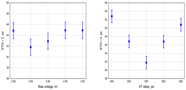
- [Section 5 (Fig. 14) and Section 4 (Fig. 9)] The per-chamber resolution is derived as sigma_diff/sqrt(2), with the explicit statement 'assuming both MRPCs contribute identically'. The two chambers under test are not identical: one has 10 gas gaps and the other has 12 gas gaps (Section 2), and Fig. 2 shows different signal amplitudes and shapes for the two chambers. If the intrinsic resolutions differ, the quoted value is a mixture of the two resolutions, not the resolution of either chamber. Please provide an independent calibration of each chamber (for example, against a reference detector of known resolution, or using a three-chamber deconvolution), or clearly report the pair resolution as the headline and quantify the bias introduced by the equal-contribution assumption.
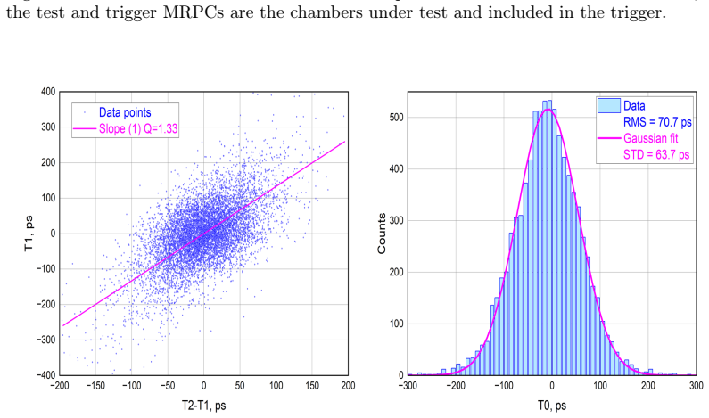
- [Section 5, Eq. (3) and Figs. 13-14] The correction factor Q and the nonlinear correction function C(T2-T1) are optimized to minimize the T0 dispersion on the same dataset whose width is then quoted as the final resolution. This is an in-sample optimization and can bias the reported standard deviation downward. The authors should validate the correction on an independent subset of the data (for example, by splitting the data into calibration and validation samples) and report the out-of-sample resolution, or conservatively quote the uncorrected width from Fig. 12 (~64 ps) as the headline. The difference between 64 and 60 ps is modest, but the abstract's 40 ps per-chamber value is derived from the corrected width, so the issue is load-bearing.
- [Section 5, Figs. 12-15] No statistical or systematic uncertainties are reported for the RMS values or Gaussian standard deviations. The key comparisons (64 ps vs 59 ps vs 60 ps) are within about 5 ps, and without error bars it is not possible to judge whether the nonlinear correction provides a real improvement. Please provide at least statistical uncertainties from the fits and account for the degrees of freedom consumed by optimizing Q and the polynomial coefficients of C(T2-T1).
minor comments (6)
- [Section 1] The word 'Secton' in the last sentence of Section 1 is a typo; it should be 'Section'.
- [Section 3] The spelling 'LTspise' should be 'LTspice'. In addition, the sentence 'It has an overall DC gain of 19 (being 50-Ohm loaded)' could be rephrased for clarity.
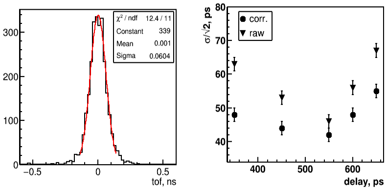
- [Abstract and Conclusions] The text uses 'total time resolution' in the abstract and 'time resolution of a single MRPC' in Sections 4-5. Please define precisely whether the quoted ~40 ps refers to an individual chamber or to the two-chamber pair, and use consistent terminology throughout.
- [Section 5, Fig. 13] The optimized linear factor Q = 0.7 differs from the nominal Q = 1.33 expected from the threshold ratio R = V2/V1. Please comment on whether this discrepancy is explained quantitatively by the comparator offset or noise, given that Fig. 6 already indicates a 1.9 mV offset.
- [Section 5] The number of events in the beam-test distributions is not stated. This information should be provided so that the statistical weight of the quoted standard deviations can be assessed.
- [Section 4, Fig. 10] The vertical scale and error bars in Fig. 10 are not described in the caption; please specify whether the points are statistical fit results and what the error bars represent.
Circularity Check
The reported ~40 ps single-chamber resolution is partly an in-sample optimum: Eq. (3)'s correction function is fitted to minimize the T0 dispersion that is then quoted as the achieved resolution.
-
fitted input called prediction
[Section 5, Eq. (3) and Fig. 14 (muon beam test)]
"T0 = T1 − C(T2 − T1), (3) where C(T2 − T1) is a correction function that minimizes the T0 dispersion (either RMS from the data or standard deviation from the fit) for the given data set. ... The resulting T0 distribution for the two MRPCs calculated using expression (3) is shown in the right panel of Fig.14 ... The RMS from the data and standard deviation from the fit are ∼67 ps and ∼60 ps, respectively."
The reported resolution value is the same quantity that defines C(T2−T1): the correction function is chosen to minimize the T0 dispersion on that exact data set, and the minimized dispersion is then quoted as the achieved time resolution. This is an in-sample fit, not an independent measurement or prediction; no validation dataset or cross-check is provided. The paper also scans Q in Fig. 13 to minimize the same width, further showing that the quoted number is an optimization target. The circularity is partial because the dominant detector, CFD, and TDC contributions are not determined by C, and the improvement over the uncorrected/linear widths is modest (about 64 to 60 ps).
full rationale
The central measurement is the MRPC time resolution obtained from the T0 time difference between two chambers. The key circular step is in Section 5: C(T2−T1) in Eq. (3) is explicitly defined as the function that minimizes the T0 dispersion on the same data set whose width is later reported as the resolution, so the quoted ~60 ps (and hence the ~40 ps single-chamber claim after dividing by sqrt(2)) is partly the minimized value of the fitting objective. The sqrt(2) deconvolution assumes the 10-gap and 12-gap chambers contribute identically; this is a statistical assumption that can bias the per-chamber estimate, but it is not itself circular. The iterative algorithm from Ref. [7] is a methodological citation rather than a self-citation chain that forbids alternatives. Apart from the in-sample correction, the CFD electronics characterization and the comparison to the SPD requirement are self-contained measurements, so the circularity is partial rather than total.
Assumptions & free parameters
free parameters (6)
- Correction factor Q in Eq. (1)/(3) =
1.16 (RMS) or 0.7 (Gaussian fit)
- Polynomial coefficients of correction function C(T2-T1) =
Not tabulated
- Electronics resolution constants C0, C1, C2 in Eq. (2) =
C0 consistent with ~17 ps TDC; C1, C2 not given numerically
- Comparator offset =
1.9 mV
- MRPC signal rise/fall times =
416 ps / 509 ps, 160 ps pole
- CFD delay =
0.55 ns
assumptions (4)
- domain assumption Formula (1), T0 = (V2*T1 - V1*T2)/(V2-V1), is valid only for linear signal rise and negligible electronics noise.
- domain assumption The two MRPCs under test contribute identically to the T0 width, so the single-chamber resolution is the two-chamber width divided by sqrt(2).
- domain assumption The intrinsic MRPC time resolution is about 20 ps, based on a Townsend-model simulation from Ref. [25].
- domain assumption Time of flight between the two test MRPCs is negligible for muons with beta > 0.94 after the lead filter.
Cite this review
Pith. "Pith review of Design and implementation of the constant fraction discriminator for glass MRPC timing." pith.science (2026). https://pith.science/paper/CJA3J2BG
@misc{pith2026250522044,
  author       = {Pith},
  title        = {Pith review of: Design and implementation of the constant fraction discriminator for glass MRPC timing},
  year         = {2026},
  howpublished = {\url{https://pith.science/paper/CJA3J2BG}},
  note         = {Machine review of arXiv:2505.22044}
}
read the original abstract
The analog front-end electronics based on the constant fraction discrimination method is designed and optimized for the Multigap Resistive Plate Chamber (MRPC) timing measurements. The total time resolution of 40 ps has been obtained for 10 and 12 gaps MRPCs using cosmic setup and a muon beam at the IHEP U-70 accelerator in Protvino, which complies with the conditions of the SPD experiment at NICA.
Figures


Figures from the paper (11 more)





Reference graph
Works this paper leans on
-
[7]
Kuzmin, et al., High-rate glass MRPC for fixed target experi- ments at Nuclotron, Nucl
N.A. Kuzmin, et al., High-rate glass MRPC for fixed target experi- ments at Nuclotron, Nucl. Instrum. Methods A 916 (2019) 190-194, http://dx.doi.org/10.1016/j.nima.2018.11.098
-
[1]
A. Akindinov, et al, Results from a large sample of MRPC-strip pro- totypes for the ALICE TOF detector, Nucl. Instrum. Methods A 532 (2004) 611-621, http://dx.doi.org/10.1016/j.nima.2004.05.125
-
[2]
Akindinov, et al., Final test of the MRPC production for the AL- ICE TOF detector, Nucl
A. Akindinov, et al., Final test of the MRPC production for the AL- ICE TOF detector, Nucl. Instrum. Methods A 602 (2009) 709-712, http://dx.doi.org/10.1016/j.nima.2008.12.095
-
[3]
A. Akindinov, et al., The MRPC-based ALICE time-of-flight detector: Commissioning and first performance, Nucl. Instrum. Methods A 661 (2012) S98-S101, http://dx.doi.org/10.1016/j.nima.2010.09.037
-
[4]
Ammosov, et al., The HARP resistive plate chambers: Character- istics and physics performance, Nucl
V. Ammosov, et al., The HARP resistive plate chambers: Character- istics and physics performance, Nucl. Instrum. Methods A 578 (2007) 119-138, http://dx.doi.org/10.1016/j.nima.2007.04.166
-
[5]
Yi Wang, et al., Production and quality control of STAR- TOF MRPC, Nucl. Instrum. Methods A 613 (2010) 200-206, http://dx.doi.org/10.1016/j.nima.2009.11.045
-
[6]
Sung Park, Production of RPC gaps for the PHENIX up- grade, Nucl. Instrum. Methods A 661 (2012) S82-S85, http://dx.doi.org/10.1016/j.nima.2010.09.181
-
[8]
Afanasiev, et al., The BM@N spectrometer at the NICA ac- celerator complex, Nucl
S. Afanasiev, et al., The BM@N spectrometer at the NICA ac- celerator complex, Nucl. Instrum. Methods A 1065 (2024) 169532, https://doi.org/10.1016/j.nima.2024.169532
Show all 31 references
-
[9]
V. Abazov, et al., Technical Design Report of the Spin Physics Detector at NICA, Natural Science Review 1 (2024) 1, http://nsr- jinr.ru/index.php/nsr/article/view/35, e-Print: 2404.08317 [hep-ex]
2024
-
[10]
Kekelidze, et al., Three stages of the NICA accelerator complex, Eur
V.D. Kekelidze, et al., Three stages of the NICA accelerator complex, Eur. Phys. J. A 52 (2016) 211, http://dx.doi.org/10.1140/epja/i2016- 16211-2. 17
2016 doi
-
[11]
An, et al., A 20-ps timing device: A Multigap Resistive Plate Cham- ber with 24 gas gaps, Nucl
S. An, et al., A 20-ps timing device: A Multigap Resistive Plate Cham- ber with 24 gas gaps, Nucl. Instrum. Methods A 594 (2008) 39-43, http://dx.doi.org/10.1016/j.nima.2008.06.013
2008 doi
-
[12]
F. Anghinolfi, et.al, Precise Tracking of Cosmic Muons Using Time-over- Threshold Property of NINO ASICs, Nuclear Instruments and Methods A 533 (2004) 183-187, http://dx.doi.org/10.1016/j.nima.2004.07.024
2004 doi
-
[13]
Usenko, Modern Application-Specific Integrated Circuits for Resis- tive Plate Chambers (Review), Instrum.Exp.Tech
E.A. Usenko, Modern Application-Specific Integrated Circuits for Resis- tive Plate Chambers (Review), Instrum.Exp.Tech. 65 (2022) 6, 865-877, http://dx.doi.org/10.1134/S0020441222050293
2022 doi
-
[14]
Akindinov, et al., Design aspects and prototype test of a very precise TDC system implemented for the multigap RPC of the ALICE-TOF, Nucl
A. Akindinov, et al., Design aspects and prototype test of a very precise TDC system implemented for the multigap RPC of the ALICE-TOF, Nucl. Instrum. Methods A 533 (2004) 178-182, http://dx.doi.org/10.1016/j.nima.2004.07.023
2004 doi
-
[15]
Babkin, et al., Beam test results of the MRPC prototype for the new NA61/SHINE ToF system, Nucl.Instrum.Meth.A 1034 (2022) 166735, http://dx.doi.org/10.1016/j.nima.2022.166735
V. Babkin, et al., Beam test results of the MRPC prototype for the new NA61/SHINE ToF system, Nucl.Instrum.Meth.A 1034 (2022) 166735, http://dx.doi.org/10.1016/j.nima.2022.166735
2022
-
[16]
Babkin, et al., Time-of-Flight System for Particle Identification in the NA61/SHINE Experiment in CERN, Phys.Part.Nucl.Lett
V.A. Babkin, et al., Time-of-Flight System for Particle Identification in the NA61/SHINE Experiment in CERN, Phys.Part.Nucl.Lett. 21 (2024) 2, 121-130, http://dx.doi.org/10.1134/S1547477124020043
2024 doi
-
[17]
S. Ritt, R. Dinapoli, U. Hartmann, Application of the DRS chip for fast waveform digitizing, Nucl.Instrum.Meth.A 623 (2010) 486-488, http://dx.doi.org/10.1016/j.nima.2010.03.045
2010 doi
-
[18]
https://www.psi.ch/en/drs
-
[19]
Jinxin Liu, et al., Design of a prototype readout electronics with a few picosecond time resolution for MRPC detectors, Nucl. Instrum. Meth. A 925 (2019) 53-59, http://dx.doi.org/10.1016/j.nima.2019.01.084
2019 doi
-
[20]
Fuyue Wang, Dong Han, Yi Wang, Pengfei Lyu, Yuanjing Li, A detailed study on the intrinsic time resolution of the future MRPC detector, Nucl. Instrum. Methods A 950 (2020) 162932, http://dx.doi.org/10.1016/j.nima.2019.162932. 18
2020
-
[21]
F. Wang, D. Han, Y. Wang, et al., The study of a new time reconstruction method for MRPC read out by wave- form digitizer, Nucl. Instrum. Methods A 954 (2020) 161224, http://dx.doi.org/10.1016/j.nima.2018.09.059
2020 doi
-
[22]
D.A.Gedcke, W.J.McDonald, Aconstantfractionofpulseheighttrigger for optimum time resolution, Nucl. Instrum. Methods 55 (1967) 377-380, http://dx.doi.org/10.1016/0029-554x(67)90145-0
1967 doi
-
[23]
Knoll, Radiation Detection and Measurement, J
G.F. Knoll, Radiation Detection and Measurement, J. Wiley& Sons, Inc., New York, 4th edition, 2010
2010
-
[24]
Townsend, The conductivity produced in gases by the motion of negatively-charged ions, Nature 62 (1900) 340-341, http://dx.doi.org/10.1038/062340b0
J.S. Townsend, The conductivity produced in gases by the motion of negatively-charged ions, Nature 62 (1900) 340-341, http://dx.doi.org/10.1038/062340b0
1900 doi
-
[25]
Sciences 11 (2021) 1, 111, http://dx.doi.org/10.3390/app11010111
Yi Wang and Yancheng Yu, Multigap Resistive Plate Chambers for Time of Flight Applications, Appl. Sciences 11 (2021) 1, 111, http://dx.doi.org/10.3390/app11010111
2021 doi
-
[26]
https://www.analog.com/media/en/technical-documentation/ datasheets/ad8099.pdf
-
[27]
https://ltspice.en.softonic.com
-
[28]
https://www.analog.com/media/en/technical-documentation/data- sheets/max9600-max9602.pdf
-
[29]
https://afi.jinr.ru/TDC64V
-
[30]
Ivanov, et al., Accelerator complex U70 of IHEP: Present status and recent upgrades, ICFA Beam Dyn
S. Ivanov, et al., Accelerator complex U70 of IHEP: Present status and recent upgrades, ICFA Beam Dyn. Newslett. 53 (2010) 51
2010
-
[31]
D. Abbaneo, et al., Design of a constant fraction discriminator for the VFAT3 front-end ASIC of the CMS GEM detector, Journal of Instrumentation 11 (2016) C01023, http://dx.doi.org/10.1088/1748- 0221/11/01/C01023. 19
2016 doi
Reviewed August 7, 2026 · model on record in the stance chip above.
Discussion (0). Sign in to comment.