REVIEW 3 major objections 5 minor 84 references
Turbulent separation control with a tilted wavy wall: a promising approach for energy savings in aerodynamic systems
T0 review · 3 major / 5 minor · reviewed 2026-08-07 · deepseek-v4-flash
Pith's one-line read This paper claims that counter-streamwise tilting of a sinusoidal wavy wall eliminates separation bubbles in the troughs, cutting the drag coefficient by 14% and raising wall shear stress by roughly 70% relative to the optimal sinusoidal…
desk verdict Tilted wavy walls are a genuine and plausible passive control tweak, but the headline numbers need grid verification for the new shapes before they become more than a promising LES result. read the letter →
The pith
A machine-rendered reading of the paper's core claim, the machinery that carries it, and where it could break.
The reading
What carries the argument
The central object is the tilted wavy wall generated by the iterative phase-shift formula $y_i = \sin(x\,2\pi N_\lambda/L_{x,w} + y_{i-1}/s) + y_{i-1}$, normalized and scaled by the amplitude $A$. The tilt parameter $s$ and iteration count $I$ control how far the crests lean counter-streamwise (WL) or streamwise (WR). Mechanically, the tilt makes the uphill side of each wave steeper, producing a strong local pressure drop and flow acceleration, which raises the wall-normal velocity gradient and hence wall shear stress on the crests; at the same time the gentler downhill side avoids the closed separation bubbles that form in symmetric sinusoidal troughs. The result is a surface that combines high wall shear stress with low shape drag.
What would settle it
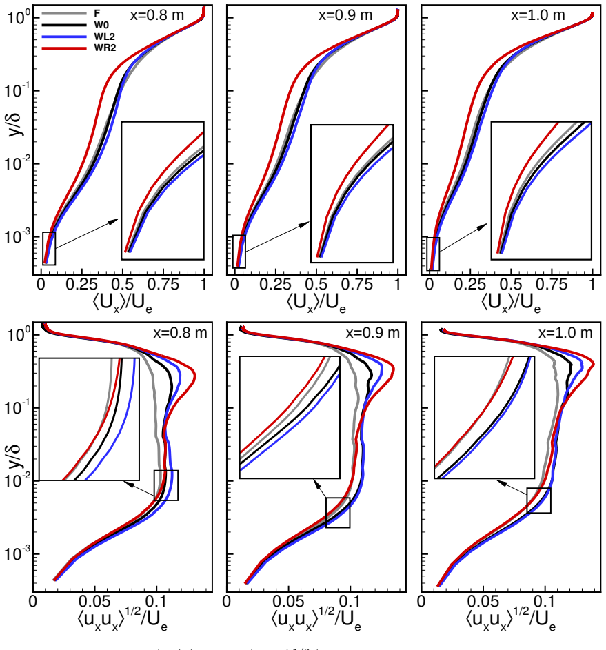
Run the WL2 configuration at $Re_\tau=2500$ on a substantially finer mesh or with a different subgrid-scale model, or measure a physical model in a wind tunnel: if the drag coefficient does not come out about 14% below the W0 value and the spatially averaged wall-shear-stress gain does not approach $\Delta\tau_{w,\mathrm{avg}}=18.4\%$, the claimed benefit is not robust; a direct check of the mechanism is to confirm that WL2 troughs are free of time-averaged reverse flow while W0 and WR2 troughs show separation bubbles.
Extended reading notes
Core claim
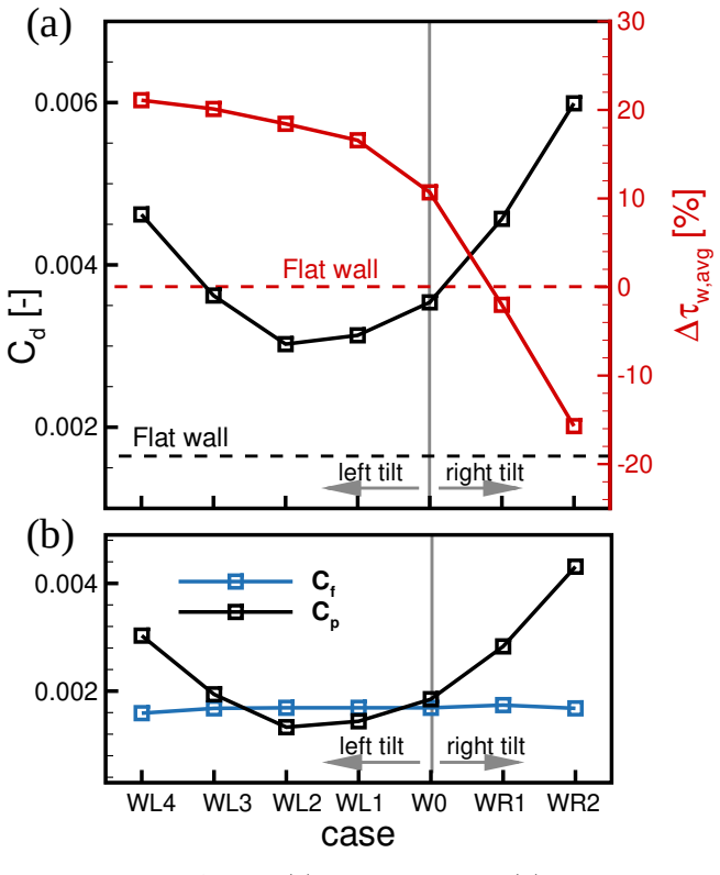
The central claim is that counter-streamwise tilting of a two-dimensional sinusoidal waviness produces a wall shape that is simultaneously better at postponing turbulent separation and cheaper in drag than the optimized sinusoidal shape. The wall shapes are generated by iteratively adding a phase shift proportional to the previous height, $y_i = \sin(x\,2\pi N_\lambda/L_{x,w} + y_{i-1}/s) + y_{i-1}$, then normalizing to the prescribed amplitude. In the LES at $Re_\tau=2500$, the WL2 configuration gives $C_d$ about 14% lower than the W0 sinusoidal case and a spatially averaged wall-shear-stress gain $\Delta\tau_{w,\mathrm{avg}} = 18.4\%$ versus $10.7\%$ for W0, about 70% higher. The paper explains this by the absence of time-averaged separation zones in the WL2 troughs: the steeper uphill slope accelerates the flow strongly, raising the near-wall velocity gradient, while the gentler downhill slope avoids closed reverse-flow bubbles, so viscous drag outweighs pressure (shape) drag. Steeper counter-streamwise tilts (WL3, WL4) push the shear-stress gain to 20.11% and 21.57% but bring drag back up, while streamwise tilts (WR1, WR2) worsen separation and produce negative shear-stress gains.
Load-bearing premise
The numerical setup validated for the sinusoidal waviness is assumed to be equally accurate for the tilted shapes, since the same 41.1-million-cell meshes and the WALE subgrid model are used for the WL and WR cases with no separate grid-independence or experimental check reported for those new geometries.
Editorial extensions
If this is right
- Counter-streamwise tilt becomes a new design degree of freedom for passive separation control: at the same amplitude, it outperforms the optimal sinusoidal waviness on both wall shear stress and local drag.
- If separation postponement is the only goal, steeper tilts (WL3, WL4) offer roughly 88% and 102% higher wall shear stress than W0, with WL3 keeping drag nearly unchanged and WL4 accepting a clear drag penalty.
- Streamwise-tilted shapes (WR1, WR2) are the wrong choice for separation control because they reduce wall shear stress below the flat-wall level, but their elevated outer-layer fluctuations make them candidates for heat-transfer or mixing applications.
- The paper's design rule, prevent separation bubbles in the troughs, can guide future corrugation optimization by treating amplitude and tilt as independent parameters to maximize wall shear stress at minimal drag.
Reading between the lines
- Beyond the paper, the same iterative tilt construction could be applied to non-sinusoidal base profiles; the testable claim is that suppression of trough separation, rather than the specific sine-phase formula, is what delivers the simultaneous gain.
- The optimal tilt likely depends on amplitude and Reynolds number, since the amplitude is scaled to boundary-layer thickness; a different $Re_\tau$ may require a different tilt parameter $s$, so amplitude and tilt should be co-optimized rather than tuned separately.
- A direct experimental check is feasible: a wind-tunnel model of WL2 over a flat plate with an adverse pressure gradient could measure $C_d$ and wall shear stress, and the absence of time-averaged reverse flow in the troughs would confirm the mechanism.
- If validated, local waviness patches on suction sides or diffuser walls could convert part of the paper's local drag reduction into system-level energy savings, but the transfer depends on interaction with the rest of the boundary layer.
Editorial analysis
A structured set of objections, weighed in public.
Referee Report
Summary. The paper extends a previously validated wavy-wall separation-control concept by introducing a streamwise tilt to the sinusoidal waviness. Seven tilted variants (WL1–WL4, WR1–WR2) are generated with an iterative mapping, and wall-resolved LES (41.1 million cells, WALE SGS model) is run in the same adverse-pressure-gradient boundary-layer configuration used in the authors' prior work. The central claim is that the counter-streamwise-tilted case WL2 reduces the local drag coefficient by about 14% relative to the untilted waviness W0 and increases the averaged wall-shear-stress gain from Δτw,avg = 10.7% to 18.4% (about 72% higher than W0). The authors attribute this improvement to acceleration on the uphill slopes and suppression of separation bubbles in the troughs; streamwise-tilted WR cases show larger separation and degraded performance.
Significance. If the reported differences are robust, this is a valuable and potentially practical result: a purely geometric modification of an already validated passive separation-control device improves both wall-shear-stress control and local form drag simultaneously. The paper is careful to compare against a previously validated W0 baseline, reports a systematic parameter sweep, and provides a credible mechanistic explanation with supporting velocity, pressure, and vorticity fields. The headline numbers are direct simulation outputs and do not appear to be fitted. The main limitations are that the quantitative claims rest on numerical verification performed only for W0, not for the tilted shapes, and that no statistical uncertainty is attached to any reported mean. These gaps must be addressed before the 14% and 72% figures can be considered fully established.
major comments (3)
- [Section 3] The numerical setup is validated only for the untilted W0 geometry (and the flat wall), and the paper asserts that 'the complexity of these configurations is similar... it is expected that the simulations reported in this paper are as accurate as those reported earlier.' This expectation is not verification. The tilted walls have steeper local slopes and different curvature at the troughs, and the same total mesh count (41.1×10^6 cells) does not guarantee the same near-wall resolution or the same WALE-model behavior in the small separation bubbles that the paper itself identifies. Since the central quantitative claims are the 14% reduction in C_d and the 72% increase in Δτw,avg for WL2 relative to W0, the paper needs a grid-refinement study and/or an SGS sensitivity check for at least WL2 and WR2, together with a report of y+ and mesh statistics for those cases. Without this, the headline differences may be numerical artifacts rather than physical effects.
- [Fig. 12 and Section 3] All performance metrics (C_d, Δτw,avg, C_f, C_p) are single-realization time averages over a 3.6 s interval (about 40 flow-through times), but the paper gives no standard error, no block-averaging convergence test, and no sensitivity to the averaging-window length. The differences that support the ranking (e.g., Δτw,avg = 18.4% for WL2 versus 10.7% for W0; C_d approximately 14% lower for WL2) are the entire basis of the paper's conclusion, so they need uncertainty estimates. Please add error bars or confidence intervals derived from sub-averaging the time series.
- [Section 4, Fig. 12, and Section 5] The drag coefficient used for the 14% claim is integrated only over the wavy-wall section (0 < x < 0.666 m), while the wall-shear-stress metric is evaluated downstream over 0.7 m < x < 1.1 m. The title and abstract promise 'energy savings in aerodynamic systems,' but the paper provides no net-drag or energy balance over the whole configuration, and it does not show that the local C_d reduction survives when the downstream pressure recovery is included. Please either quantify the net effect over the entire measurement section or state explicitly, including in the abstract, that the 14% drag reduction is local to the wavy section.
minor comments (5)
- [Abstract] The abstract's '70% better performance' is ambiguous; the body reports Δτw,avg rising from 10.7% to 18.4%, a 72% relative increase, not a 70% increase in wall-shear stress itself. Please state the metric explicitly.
- [Abstract and Fig. 7] The abstract says tilting 'eliminates the occurrence of separation zones in waviness troughs,' but the body reports a small region with ⟨τw,x⟩ < 0 for WL2 at x/λ ≈ 4.27, described as 'too minor to be visible.' Please reconcile the wording, for instance by defining a quantitative threshold for a separation zone.
- [Section 4] The notation Δτw, Δ⟨τw,x⟩, and Δτw,avg is used inconsistently across Fig. 11, Fig. 12, and the text; define these three quantities once and use them consistently.
- [Section 2, Eqs. (1)–(3)] The iterative shape-generation parameters in Table I are not fully transparent; please report the maximum local slope or phase shift of each generated shape and confirm that the shapes do not self-intersect for the larger tilt levels (WL3, WL4).
- [Section 3] The statement that the meshes for the tilted cases 'slightly differ' should be supported by a table of mesh characteristics (cell distribution, y+ at crests and troughs) rather than a qualitative assertion.
Circularity Check
No significant circularity: the 14% drag and 72.4% shear-stress figures are LES outputs for a new geometry, not fitted targets; the self-cited validation is independent evidence.
full rationale
The derivation chain starts from the explicit geometry-generating equations (1)-(3): y_i = sin(x 2πNλ/Lx,w + y_{i-1}/s) + y_{i-1}, normalized by max|y_I| and scaled by the fixed amplitude A. The headline quantities (Cd, Δ⟨τw,x⟩avg) are then evaluated from time-averaged LES solutions, not obtained by fitting a parameter to the reported outcome. The baseline W0 is taken from the authors' earlier amplitude study (A0=1.2, Refs. [1,62]), but WL2 was not selected by optimizing a fit to 14% or 18.4%; the paper reports the observed values over a family of tilts. The only notable self-reference is the validation transfer in Section 3: 'The above-outlined solution procedure ... as accurate as those reported earlier.' This is not a circular derivation: Ref. [1] validates the same 41.1M-cell mesh, time-step, and WALE setup against experimental velocity and fluctuation measurements, so the citation is independent support rather than an imported conclusion. The unverified step is the assumption that the grid-independence established for W0 transfers to the steeper tilted WL/WR geometries; this is a missing numerical check (a correctness risk), not a definitional or statistical reduction of the prediction to its inputs. No equation defines a headline quantity in terms of itself, no fitted value is renamed as a prediction, and no uniqueness/ansatz is imposed by self-citation.
Assumptions & free parameters
free parameters (4)
- Amplitude scaling A0 =
1.2
- Amplitude growth coefficients a, b, c in A(x) =
0.00366, 0.000614, 0.003351 m
- Tilt parameter s and iteration count I =
s=1,2 with I=2..4 for WL; s=-1,-2 with I=2 for WR
- Number of periods N_lambda and wavelength lambda =
N_lambda=5, lambda=0.1332 m
assumptions (6)
- domain assumption The WALE subgrid model with the stated mesh accurately reproduces turbulent separation for tilted walls.
- domain assumption Wall-resolved 41.1 million-cell meshes are grid-independent for all WL/WR geometries.
- domain assumption The truncated domain and inlet/top boundary conditions from Ref. [1] remain valid for new geometries.
- domain assumption Averaging over 3.6 s of physical time is sufficient to converge mean wall shear stress and drag.
- domain assumption Periodic spanwise width 0.24 m is wide enough to contain relevant vortical structures.
- ad hoc to paper Local drag over the waviness section captures the energy-savings potential.
Cite this review
Pith. "Pith review of Turbulent separation control with a tilted wavy wall: a promising approach for energy savings in aerodynamic systems." pith.science (2026). https://pith.science/paper/IIHFF5WO
@misc{pith2026250522611,
  author       = {Pith},
  title        = {Pith review of: Turbulent separation control with a tilted wavy wall: a promising approach for energy savings in aerodynamic systems},
  year         = {2026},
  howpublished = {\url{https://pith.science/paper/IIHFF5WO}},
  note         = {Machine review of arXiv:2505.22611}
}
read the original abstract
Recently, Kami\'nski et al. [1] demonstrated that a two-dimensional streamwise waviness with carefully selected amplitude and period can be effectively used in postponement of a flow separation at high Reynolds number which is out of reach for other commonly known passive flow control strategies. This paper demonstrates that this approach can be substantially improved by introducing a novel type of surface waviness characterized by tilting the subsequent waves. The research is performed by applying the Large Eddy Simulation (LES) method allowing for a detailed analysis of both instantaneous and time-averaged flow characteristics. It is shown that the tilting eliminates the occurrence of separation zones in waviness troughs, which minimizes the shape drag and maximizes the wall shear stress. In particular, compared to an optimal classical sinusoidal waviness shape the drag coefficient drops 14%. Simultaneously, 70% better performance in separation control is achieved. Moreover, it is also shown that when this issue is a priority, even further improvement can be achieved, though at the expense of greater drag.
Figures


Figures from the paper (10 more)


Reference graph
Works this paper leans on
-
[74]
Turbulent boundary layer over 2d and 3d large-scale wavy walls,
A. M. Hamed, A. Kamdar, L. Castillo, and L. P. Chamorro, “Turbulent boundary layer over 2d and 3d large-scale wavy walls,”Physics of Fluids, vol. 27, no. 10, p. 106601, 2015
work page 2015
-
[1]
Introduction The energy efficiency of aerodynamic systems, such as an airplane wing, strongly depends on its near-wall flow dynamics. When a flow experiences an adverse pressure gradient (APG), which is present on the suction side of an airfoil, the separation of the turbulent boundary layer (TBL) is likely to occur when the streamwise component of the wa...
-
[2]
suction chamber eliptical edge 0.3 m
Research object suction chamber inlet 1200 mm (measuring region) overpressure grid at the outlet flat plate dp/dx = 0 d p/dx > 0 317 mm 500 mm (perforated wall) x = 0 x 5035 mm (inlet section) 1835 mm (test section) tripping eliptical edge 300 mm y l L = 500 mm suction chamber inlet 1200 mm (measuring region) overpressure grid at the outlet flat plate dp/dx...
-
[3]
The spatial discretization of the Navier-Stokes equations was accomplished with a bounded 2nd order central differencing scheme
Numerical model and boundary conditions The simulations are conducted using the ANSYS Fluent software, employing the Wall- Adapting Local Eddy-viscosity (WALE) subgrid model. The spatial discretization of the Navier-Stokes equations was accomplished with a bounded 2nd order central differencing scheme. A 2 nd order scheme is also used for the discretizati...
-
[4]
On the other hand, it is known that any interference with the shape of the streamlined surface can contribute to the total drag
Results As discussed in the introduction, the main goal of the research is to increaseτw, which will ensure the delay or complete elimination of TBL separation under the influence of a strong positive pressure gradient. On the other hand, it is known that any interference with the shape of the streamlined surface can contribute to the total drag. The purp...
-
[5]
Moreover, this increase is accompanied by a local reduction in the drag force coefficient
Summary This paper demonstrates that counter-streamwise tilting of the wall waviness leads to a significant increase in wall shear stress compared to that observed with the classical sinu- soidal wall shape. Moreover, this increase is accompanied by a local reduction in the drag force coefficient. At its minimum value,Cd, computed for the area occupied by...
-
[6]
Acknowledgements The investigation was supported by the National Science Centre under Grant No. UMO- 2020/39/B/ST8/01449. The simulations were carried out using the PL-Grid computer in- frastructure. 21
work page 2020
-
[7]
Nu- merical analysis of novel wavy wall based control of turbulent boundary layer separation,
P. Kamiński, P. Niegodajew, A. Dróżdż, V. Sokolenko, A. Tyliszczak, and W. Elsner, “Nu- merical analysis of novel wavy wall based control of turbulent boundary layer separation,” Aerospace Science and Technology, vol. 149, p. 109167, 2024
work page 2024
Show all 84 references
-
[8]
Low-reynolds-number separation on an airfoil,
J. M. Lin and L. L. Pauley, “Low-reynolds-number separation on an airfoil,”AIAA journal, vol. 34, no. 8, pp. 1570–1577, 1996
1996
-
[9]
Effect of adverse pressure gradients on turbulent wing boundary layers,
Á. Tanarro, R. Vinuesa, and P. Schlatter, “Effect of adverse pressure gradients on turbulent wing boundary layers,”Journal of Fluid Mechanics, vol. 883, p. A8, 2020
2020
-
[10]
Turbulent flow in a conical diffuser: A review,
R. S. Azad, “Turbulent flow in a conical diffuser: A review,”Experimental Thermal and Fluid Science, vol. 13, no. 4, pp. 318–337, 1996
1996
-
[11]
Computation of developing turbulent flow through a straight asymmetric diffuser with moderate adverse pressure gradient,
S. Salehi, M. Raisee, and M. Cervantes, “Computation of developing turbulent flow through a straight asymmetric diffuser with moderate adverse pressure gradient,”Journal of Applied Fluid Mechanics, vol. 10, no. 4, pp. 1029–1043, 2017
2017
-
[12]
Yadegari and A
M. Yadegari and A. B. Khoshnevis, “Numerical study of the effects of adverse pressure gradient parameter, turningangleandcurvatureratioonturbulentflowin3dturningcurvedrectangular diffusers using entropy generation analysis,”The European Physical Journal Plus, vol. 135, no. 7, ...
2020
-
[13]
Experimental study of wind-turbine airfoil aerody- namics in high turbulence,
P. Devinant, T. Laverne, and J. Hureau, “Experimental study of wind-turbine airfoil aerody- namics in high turbulence,”Journal of Wind Engineering and Industrial Aerodynamics, vol. 90, no. 6, pp. 689–707, 2002
2002
-
[14]
Simulations of transition and separation past a wind-turbine airfoil near stall,
W. Cui, Z. Xiao, and X. Yuan, “Simulations of transition and separation past a wind-turbine airfoil near stall,”Energy, vol. 205, p. 118003, 2020
2020
-
[15]
A comprehensive three-dimensional study on darrieus verti- cal axis wind turbine with slotted blade to reduce flow separation,
A. Abdolahifar and S. Karimian, “A comprehensive three-dimensional study on darrieus verti- cal axis wind turbine with slotted blade to reduce flow separation,”Energy, vol. 248, p. 123632, 2022
2022
-
[16]
Delayed detached eddy simulation of the wind turbine airfoil s809 for angles of attack up to 90 degrees,
H.-Y. Xu, C.-L. Qiao, H.-Q. Yang, and Z.-Y. Ye, “Delayed detached eddy simulation of the wind turbine airfoil s809 for angles of attack up to 90 degrees,”Energy, vol. 118, pp. 1090–1109, 2017
2017
-
[17]
Influence of an off-surface small structure on the flow control effect on horizontal axis wind turbine at different relative inflow angles,
Y. Wang, G. Li, S. Shen, D. Huang, and Z. Zheng, “Influence of an off-surface small structure on the flow control effect on horizontal axis wind turbine at different relative inflow angles,” 22 Energy, vol. 160, pp. 101–121, 2018
2018
-
[18]
Analyzing the impact of blade geometrical parameters on energy recovery and efficiency of centrifugal pump as turbine installed in the pressure-reducing station,
M. H. Shojaeefard and S. Saremian, “Analyzing the impact of blade geometrical parameters on energy recovery and efficiency of centrifugal pump as turbine installed in the pressure-reducing station,”Energy, vol. 289, p. 130004, 2024
2024
-
[19]
Co-adjustable guide vane and diffuser vane to improve the energy generation potential of an axial-flow pump as turbine,
D.-A. Nguyen and J.-H. Kim, “Co-adjustable guide vane and diffuser vane to improve the energy generation potential of an axial-flow pump as turbine,”Energy, vol. 291, p. 130325, 2024
2024
-
[20]
A review of turbulent skin-friction drag reduction by near-wall transverse forcing,
P. Ricco, M. Skote, and M. A. Leschziner, “A review of turbulent skin-friction drag reduction by near-wall transverse forcing,”Progress in Aerospace Sciences, vol. 123, p. 100713, 2021
2021
-
[21]
A review of recent developments in flow control,
P. Ashill, J. Fulker, and K. Hackett, “A review of recent developments in flow control,”The Aeronautical Journal, vol. 109, no. 1095, pp. 205–232, 2005
2005
-
[22]
Passive and active control of turbulent flows,
S. Ghaemi, “Passive and active control of turbulent flows,”Physics of fluids, vol. 32, no. 8, 2020
2020
-
[23]
On the active and passive flow separation control tech- niques over airfoils,
T. Moghaddam and N. B. Neishabouri, “On the active and passive flow separation control tech- niques over airfoils,” inIOP Conference Series: Materials Science and Engineering, vol. 248, p. 012009, IOP Publishing, 2017
2017
-
[24]
Issues in active flow control: theory, control, simulation, and experiment,
S. S. Collis, R. D. Joslin, A. Seifert, and V. Theofilis, “Issues in active flow control: theory, control, simulation, and experiment,”Progress in aerospace sciences, vol. 40, no. 4-5, pp. 237– 289, 2004
2004
-
[25]
Drag reduction with teardrop-shaped dimples,
J. Tay and T. T. Lim, “Drag reduction with teardrop-shaped dimples,” in2018 Flow Control Conference, p. 3528, 2018
2018
-
[26]
Mechanics of drag reduction by shallow dimples in channel flow,
C. Tay, B. Khoo, and Y. Chew, “Mechanics of drag reduction by shallow dimples in channel flow,”Physics of Fluids, vol. 27, no. 3, 2015
2015
-
[27]
Dimples for skin-friction drag reduction: status and perspectives,
F. Gattere, A. Chiarini, and M. Quadrio, “Dimples for skin-friction drag reduction: status and perspectives,”Fluids, vol. 7, no. 7, p. 240, 2022
2022
-
[28]
Mechanism of drag reduction by dimple structures on a sphere,
K. Aoki, K. Muto, and H. Okanaga, “Mechanism of drag reduction by dimple structures on a sphere,”Journal of Fluid Science and Technology, vol. 7, no. 1, pp. 1–10, 2012
2012
-
[29]
Drag reduction with diamond-shaped dimples,
J. Tay, T. T. Lim, and B. C. Khoo, “Drag reduction with diamond-shaped dimples,” inAIAA Aviation 2019 Forum, p. 3296, 2019
2019
-
[30]
Passive flow-field control using dimples for performance enhancement of horizontal axis wind turbine,
F. Azlan, M. K. Tan, B. T. Tan, and M.-Z. Ismadi, “Passive flow-field control using dimples for performance enhancement of horizontal axis wind turbine,”Energy, vol. 271, p. 127090, 2023. 23
2023
-
[31]
Research on aerodynamic drag reduction by vortex generators,
M. Koike, T. Nagayoshi, and N. Hamamoto, “Research on aerodynamic drag reduction by vortex generators,”Mitsubishi motors technical review, vol. 16, pp. 11–16, 2004
2004
-
[32]
Drag and lift reduction of a 3d bluff-body using active vortex generators,
J.-L. Aider, J.-F. Beaudoin, and J. E. Wesfreid, “Drag and lift reduction of a 3d bluff-body using active vortex generators,”Experiments in fluids, vol. 48, pp. 771–789, 2010
2010
-
[33]
Helicopter drag reduction by vortex generators,
G. Gibertini, J. Boniface, A. Zanotti, G. Droandi, F. Auteri, R. Gaveriaux, and A. Le Pape, “Helicopter drag reduction by vortex generators,”Aerospace science and technology, vol. 47, pp. 324–339, 2015
2015
-
[34]
Dynamic stall control of the wind turbine airfoil via single-row and double-row passive vortex generators,
C. Zhu, J. Chen, J. Wu, and T. Wang, “Dynamic stall control of the wind turbine airfoil via single-row and double-row passive vortex generators,”Energy, vol. 189, p. 116272, 2019
2019
-
[35]
Flow control on the nrel s809 wind turbine airfoil using vortex generators,
H. Wang, B. Zhang, Q. Qiu, and X. Xu, “Flow control on the nrel s809 wind turbine airfoil using vortex generators,”Energy, vol. 118, pp. 1210–1221, 2017
2017
-
[36]
Drag reduction of a car by using vortex generator,
M. R. Islam, M. A. Hossain, M. Mashud, and M. T. I. Gias, “Drag reduction of a car by using vortex generator,”International Journal of Scientific & Engineering Research, vol. 4, no. 7, pp. 1298–1302, 2013
2013
-
[37]
Aerodynamic performance analysis of slot- ted airfoils for application to wind turbine blades,
R. Belamadi, A. Djemili, A. Ilinca, and R. Mdouki, “Aerodynamic performance analysis of slot- ted airfoils for application to wind turbine blades,”Journal of wind engineering and industrial aerodynamics, vol. 151, pp. 79–99, 2016
2016
-
[38]
Design of a slotted, natural-laminar-flow airfoil for commercial transport applications,
J. G. Coder and D. M. Somers, “Design of a slotted, natural-laminar-flow airfoil for commercial transport applications,”Aerospace Science and Technology, vol. 106, p. 106217, 2020
2020
-
[39]
Effects of leading edge slat on the aerodynamic performance of low reynolds number horizontal axis wind turbine,
A. Zaki, M. Abdelrahman, S. S. Ayad, and O. Abdellatif, “Effects of leading edge slat on the aerodynamic performance of low reynolds number horizontal axis wind turbine,”Energy, vol. 239, p. 122338, 2022
2022
-
[40]
Effects of leading edge slat on flow separation and aerodynamic performance of wind turbine,
H. Wang, X. Jiang, Y. Chao, Q. Li, M. Li, W. Zheng, and T. Chen, “Effects of leading edge slat on flow separation and aerodynamic performance of wind turbine,”Energy, vol. 182, pp. 988– 998, 2019
2019
-
[41]
Numerical study on aerodynamic performance and noise of wind turbine airfoils with serrated gurney flap,
X. Ye, J. Hu, N. Zheng, and C. Li, “Numerical study on aerodynamic performance and noise of wind turbine airfoils with serrated gurney flap,”Energy, vol. 262, p. 125574, 2023
2023
-
[42]
Impacts of gurney flap and solidity on the aerodynamic performance of vertical axis wind turbines in array configurations,
L. Ni, W. Miao, C. Li, and Q. Liu, “Impacts of gurney flap and solidity on the aerodynamic performance of vertical axis wind turbines in array configurations,”Energy, vol. 215, p. 118915, 2021. 24
2021
-
[43]
Influence of an off-surface small structure on the flow control effect on horizontal axis wind turbine at different relative inflow angles,
Y. Wang, G. Li, S. Shen, D. Huang, and Z. Zheng, “Influence of an off-surface small structure on the flow control effect on horizontal axis wind turbine at different relative inflow angles,” Energy, vol. 160, pp. 101–121, 2018
2018
-
[44]
Quantitative impact of a micro-cylinder as a passive flow control on a horizontal axis wind turbine perfor- mance,
W. Mostafa, A. Abdelsamie, M. Sedrak, D. Thévenin, and M. H. Mohamed, “Quantitative impact of a micro-cylinder as a passive flow control on a horizontal axis wind turbine perfor- mance,”Energy, vol. 244, p. 122654, 2022
2022
-
[45]
Wake-triggered secondary vortices over a cylinder/airfoil configuration,
J.-S. Wang, J. Wu, and J.-J. Wang, “Wake-triggered secondary vortices over a cylinder/airfoil configuration,”Experiments in Fluids, vol. 64, no. 1, p. 6, 2023
2023
-
[46]
Dynamic mode decomposition analysis of flow separation control on wind turbine airfoil using leading- edge rod,
J. Zhong, J. Li, and H. Liu, “Dynamic mode decomposition analysis of flow separation control on wind turbine airfoil using leading- edge rod,”Energy, vol. 268, p. 126656, 2023
2023
-
[47]
Biomimetic spiroid winglets for lift and drag control,
J. E. Guerrero, D. Maestro, and A. Bottaro, “Biomimetic spiroid winglets for lift and drag control,”Comptes Rendus Mecanique, vol. 340, no. 1-2, pp. 67–80, 2012
2012
-
[48]
Experimental investigations on drag- reduction characteristics of bionic surface with water-trapping microstructures of fish scales,
L. Wu, Z. Jiao, Y. Song, C. Liu, H. Wang, and Y. Yan, “Experimental investigations on drag- reduction characteristics of bionic surface with water-trapping microstructures of fish scales,” Scientific Reports, vol. 8, no. 1, p. 12186, 2018
2018
-
[49]
Variable cant angle winglets for improve- ment of aircraft flight performance,
J. E. Guerrero, M. Sanguineti, and K. Wittkowski, “Variable cant angle winglets for improve- ment of aircraft flight performance,”Meccanica, vol. 55, pp. 1917–1947, 2020
1917
-
[50]
Comparative analysis of bent and basic winglets on performance improvement of horizontal axis wind turbines,
Z. Zhang, L. Kuang, Z. Han, D. Zhou, Y. Zhao, Y. Bao, L. Duan, J. Tu, Y. Chen, and M. Chen, “Comparative analysis of bent and basic winglets on performance improvement of horizontal axis wind turbines,”Energy, vol. 281, p. 128252, 2023
2023
-
[51]
An efficient winglet coverage for aeroengine turbine blade flat tip and its loss map,
J. S. Jeong, S. W. Bong, and S. W. Lee, “An efficient winglet coverage for aeroengine turbine blade flat tip and its loss map,”Energy, vol. 260, p. 125153, 2022
2022
-
[52]
Investigation of a small horizontal–axis wind turbine performance with and without winglet,
M. Khaled, M. M. Ibrahim, H. E. A. Hamed, and A. F. AbdelGwad, “Investigation of a small horizontal–axis wind turbine performance with and without winglet,”Energy, vol. 187, p. 115921, 2019
2019
-
[53]
A preliminary assessment of the feasibility of using riblets in internal flows to conserve energy,
P. Lowrey and J. Harasha, “A preliminary assessment of the feasibility of using riblets in internal flows to conserve energy,”Energy, vol. 16, no. 3, pp. 631–642, 1991
1991
-
[54]
Performance improvement of adaptive flap on flow separation control and its effect on vawt,
W. Hao and C. Li, “Performance improvement of adaptive flap on flow separation control and its effect on vawt,”Energy, vol. 213, p. 118809, 2020
2020
-
[55]
Biomimetic drag reduction study on herringbone riblets of bird feather,
H. Chen, F. Rao, X. Shang, D. Zhang, and I. Hagiwara, “Biomimetic drag reduction study on herringbone riblets of bird feather,”Journal of Bionic Engineering, vol. 10, no. 3, pp. 341–349, 25 2013
2013
-
[56]
Evaluation of the efficiency of bioinspired blade designs for low-speed small-scale wind turbines with the presence of inflow turbulence effects,
W. Yossri, S. B. Ayed, and A. Abdelkefi, “Evaluation of the efficiency of bioinspired blade designs for low-speed small-scale wind turbines with the presence of inflow turbulence effects,” Energy, vol. 273, p. 127210, 2023
2023
-
[57]
Mechanical properties of shark-skin like structured surfaces for high- temperature applications,
A. Schlieter, R. Pflumm, I. Shakhverdova, R. Naraparaju, U. Schulz, C. Leyens, M. Schütze, and W. Reimers, “Mechanical properties of shark-skin like structured surfaces for high- temperature applications,”Advanced Engineering Materials, vol. 18, no. 5, pp. 688–702, 2016
2016
-
[58]
Separation control over a grooved surface inspired by dolphin skin,
A. W. Lang, E. M. Jones, and F. Afroz, “Separation control over a grooved surface inspired by dolphin skin,”Bioinspiration & Biomimetics, vol. 12, no. 2, p. 026005, 2017
2017
-
[59]
Low-reynolds-number airfoils,
P. Lissaman, “Low-reynolds-number airfoils,”Annual review of fluid mechanics, vol. 15, no. 1, pp. 223–239, 1983
1983
-
[60]
Investigation into the laminar separation control of airfoils at low reynolds numbers by dimple vortex generators,
Y. Xie, Y. Rao, Y. Cheng, and W. Tian, “Investigation into the laminar separation control of airfoils at low reynolds numbers by dimple vortex generators,”Aerospace Science and Tech- nology, vol. 129, p. 107841, 2022
2022
-
[61]
Low-speed single-element airfoil synthesis,
J. H. McMasters and M. L. Henderson, “Low-speed single-element airfoil synthesis,”NASA. Langley Res. Center The Sci. and Technol. of Low Speed and Motorless Flight, Pt. 1, 1979
1979
-
[62]
Effects of surface roughness on a separating turbulent boundary layer,
W. Wu and U. Piomelli, “Effects of surface roughness on a separating turbulent boundary layer,”Journal of Fluid Mechanics, vol. 841, p. 552–580, 2018
2018
-
[63]
Effective use of the streamwise waviness in the control of turbulent separation,
A. Dróżdż, P. Niegodajew, M. Romańczyk, V. Sokolenko, and W. Elsner, “Effective use of the streamwise waviness in the control of turbulent separation,”Experimental Thermal and Fluid Science, vol. 121, p. 110291, 2021
2021
-
[64]
Aeroacoustic study of a wavy stator leading edge in a realistic fan/ogv stage,
D. Casalino, F. Avallone, I. Gonzalez-Martino, and D. Ragni, “Aeroacoustic study of a wavy stator leading edge in a realistic fan/ogv stage,”Journal of Sound and Vibration, vol. 442, pp. 138–154, 2019
2019
-
[65]
A numerical study on aircraft noise mitigation using porous stator concepts,
C. Teruna, L. Rego, D. Casalino, D. Ragni, and F. Avallone, “A numerical study on aircraft noise mitigation using porous stator concepts,”Aerospace, vol. 9, no. 2, p. 70, 2022
2022
-
[66]
Influence of wavy wall and non-uniform heating on natural convection heat transfer and entropy generation inside porous complex enclosure,
S. Bhardwaj, A. Dalal, and S. Pati, “Influence of wavy wall and non-uniform heating on natural convection heat transfer and entropy generation inside porous complex enclosure,”Energy, vol. 79, pp. 467–481, 2015
2015
-
[67]
Numerical study of wavy-wall effects on premixed h2/air flammability limits, propagation modes, and thermal performance of micro combustion cham- 26 bers,
P. Abbaspour and A. Alipoor, “Numerical study of wavy-wall effects on premixed h2/air flammability limits, propagation modes, and thermal performance of micro combustion cham- 26 bers,”Applied Energy, vol. 359, p. 122727, 2024
2024
-
[68]
Estimation of the optimal ampli- tude and period of a wavy wall for controlling turbulent separation at Reτ = 2500,
P. Kamiński, W. Elsner, A. Tyliszczak, and P. Niegodajew, “Estimation of the optimal ampli- tude and period of a wavy wall for controlling turbulent separation at Reτ = 2500,”submitted to Aerospace Science and Technology, 2024
2024
-
[69]
Direct numerical simulation of a fully developed turbulent flow over a wavy wall,
P. Cherukat, Y. Na, T. Hanratty, and J. McLaughlin, “Direct numerical simulation of a fully developed turbulent flow over a wavy wall,”Theoretical and computational fluid dynamics, vol. 11, no. 2, pp. 109–134, 1998
1998
-
[70]
Direct numerical simulation of a fully developed compressible wall turbulence over a wavy wall,
Z. Sun, Y. Zhu, Y. Hu, and S. Zhang, “Direct numerical simulation of a fully developed compressible wall turbulence over a wavy wall,”Journal of Turbulence, vol. 19, no. 1, pp. 72– 105, 2018
2018
-
[71]
Large eddy simulations of wall heat transfer and coherent structures in mixed convection over a wavy wall,
S. Kuhn, S. Kenjereš, and P. R. von Rohr, “Large eddy simulations of wall heat transfer and coherent structures in mixed convection over a wavy wall,”International journal of thermal sciences, vol. 49, no. 7, pp. 1209–1226, 2010
2010
-
[72]
Numerical simulation of fully-developed compressible flows over wavy surfaces,
C. Tyson and N. Sandham, “Numerical simulation of fully-developed compressible flows over wavy surfaces,”International journal of heat and fluid flow, vol. 41, pp. 2–15, 2013
2013
-
[73]
Structure of turbulent heat flux in a flow over a heated wavy wall,
N. Kruse and P. R. Von Rohr, “Structure of turbulent heat flux in a flow over a heated wavy wall,”International journal of heat and mass transfer, vol. 49, no. 19-20, pp. 3514–3529, 2006
2006
-
[75]
Experimental and numerical studies of turbulent flows over two-dimensional and three-dimensional rough surfaces under an adverse pressure gradient,
W. Elsner, A. Dróżdż, E. Szymanek, A. Tyliszczak, and P. Niegodajew, “Experimental and numerical studies of turbulent flows over two-dimensional and three-dimensional rough surfaces under an adverse pressure gradient,”Applied Mathematical Modelling, vol. 106, pp. 549–566, 2022
2022
-
[76]
Langmuir-type vortices in wall-bounded flows driven by a criss-cross wavy wall topography,
A. H. Akselsen and S. Å. Ellingsen, “Langmuir-type vortices in wall-bounded flows driven by a criss-cross wavy wall topography,”Journal of Fluid Mechanics, vol. 900, p. A19, 2020
2020
-
[77]
Direct numerical simulation of turbulent flow over a wavy wall,
V. De Angelis, P. Lombardi, and S. Banerjee, “Direct numerical simulation of turbulent flow over a wavy wall,”Physics of Fluids, vol. 9, no. 8, pp. 2429–2442, 1997
1997
-
[78]
Turbulence modification in flow around a peri- odically deforming film,
S. Koyama, K. Takashima, and Y. Hagiwara, “Turbulence modification in flow around a peri- odically deforming film,”Journal of Turbulence, no. 8, p. N19, 2007
2007
-
[79]
Effect of wave amplitude on turbulent flow in a wavy channel by direct numerical simulation,
H. Yoon, O. El-Samni, A. Huynh, H. Chun, H. Kim, A. Pham, and I. Park, “Effect of wave amplitude on turbulent flow in a wavy channel by direct numerical simulation,”Ocean Engi- 27 neering, vol. 36, no. 9-10, pp. 697–707, 2009
2009
-
[80]
Turbulence structure, friction drag and pressure drag due to turbulent flow over angled wavy surfaces,
H. Fujii, K. Sakurai, T. Nakano, and Y. Hagiwara, “Turbulence structure, friction drag and pressure drag due to turbulent flow over angled wavy surfaces,” inSeventh International Sym- posium on Turbulence and Shear Flow Phenomena, Begel House Inc., 2011
2011
-
[81]
Can large-scale oblique undulations on a solid wall reduce the turbulent drag?,
S. Ghebali, S. I. Chernyshenko, and M. A. Leschziner, “Can large-scale oblique undulations on a solid wall reduce the turbulent drag?,”Physics of Fluids, vol. 29, no. 10, 2017
2017
-
[82]
Experimental and numerical investigation of developing turbulent flow over a wavy wall in a horizontal channel,
V. M. Segunda, S. J. Ormiston, and M. F. Tachie, “Experimental and numerical investigation of developing turbulent flow over a wavy wall in a horizontal channel,”European Journal of Mechanics-B/Fluids, vol. 68, pp. 128–143, 2018
2018
-
[83]
Turbulent boundary layer response to large- scale wavy topographies,
A. M. Hamed, L. Castillo, and L. P. Chamorro, “Turbulent boundary layer response to large- scale wavy topographies,”Physics of Fluids, vol. 29, no. 6, p. 065113, 2017
2017
-
[84]
Large-scale influences in near-wall turbulence,
N. Hutchins and I. Marusic, “Large-scale influences in near-wall turbulence,”Philosophi- cal Transactions of the Royal Society A: Mathematical, Physical and Engineering Sciences, vol. 365, no. 1852, pp. 647–664, 2007
2007
Reviewed August 7, 2026 · model on record in the stance chip above.
Discussion (0). Sign in to comment.