REVIEW 3 major objections 5 minor 30 references
On the flow topology of swirl jets upon impingement
T0 review · 3 major / 5 minor · reviewed 2026-08-07 · deepseek-v4-flash
Pith's one-line read Swirl jets impinging close to a flat plate produce an order of magnitude more near-wall turbulence, which the authors identify as the reason these jets transfer heat better.
desk verdict Useful swirl-impingement PIV/POD dataset, but the 'order-of-magnitude TKE' claim is under-supported by 500-image statistics and the text contradicts itself on whether impingement PIV is possible. read the letter →
The pith
A machine-rendered reading of the paper's core claim, the machinery that carries it, and where it could break.
The reading
What carries the argument
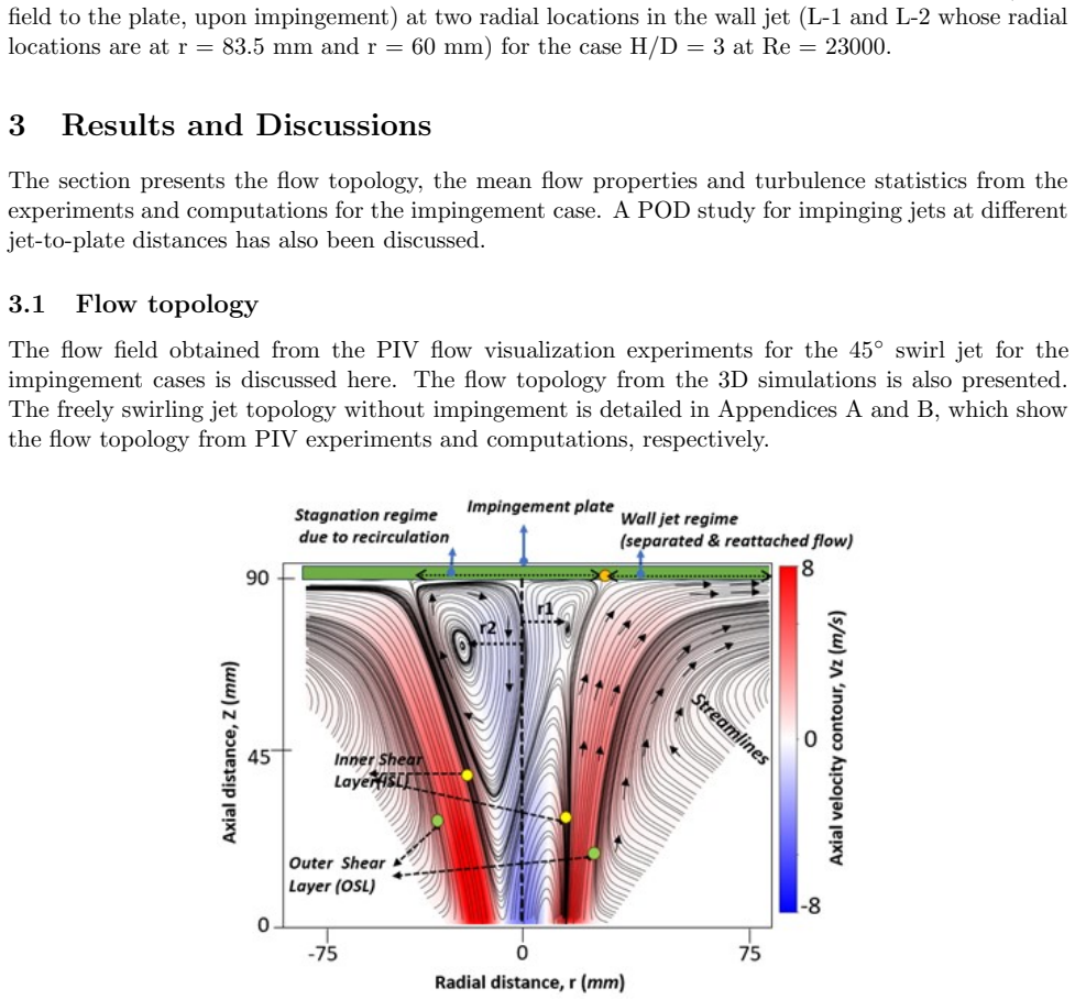
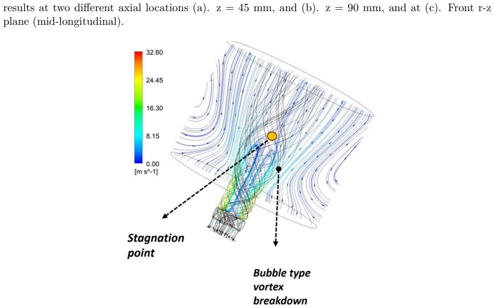
The central device is the 45-degree vane swirler (eight vanes, hub-to-outer-diameter ratio giving a geometric swirl number of about 0.7), which produces a swirl jet with a bubble-type vortex breakdown and distinct inner and outer shear layers. The control parameter that carries the argument is the dimensionless jet-plate distance H/D: at H/D≤2 the strong axial deceleration and the shear layers sit close to the plate, generating high near-wall turbulence, while at H/D=3 the swirl decays before the flow can build the same near-wall turbulence. Proper orthogonal decomposition of the PIV velocity fields is the diagnostic that reveals the compressed, self-similar coherent structures at low H/D.
What would settle it
Perform the same impingement experiments at Re=23000 for H/D=2 and H/D=3 using a longer time-resolved dataset (for example 10,000+ PIV snapshots or hot-wire traverses) and compute TKE, Reynolds shear stress, and RMS velocities in the near-wall field; if the near-wall TKE at H/D=2 is not roughly an order of magnitude above H/D=3, the paper's central claim is contradicted.
Extended reading notes
Core claim
The paper establishes that, for a turbulent swirl jet generated by a 45-degree vane swirler and impinging on a flat plate, the near-wall turbulent kinetic energy is roughly an order of magnitude higher at H/D≤2 than at larger spacings, with Reynolds shear stress and fluctuating RMS velocities also concentrated near the plate. At H/D=3 the swirl and its associated turbulence decay substantially before reaching the wall, leaving the near-wall region comparatively quiescent. This near-wall turbulence surplus is the proposed explanation for the enhanced heat transfer known for low-spacing swirl impingement. The POD analysis supports the same picture by showing that the first four modes at H/D=2 and 1.5 are self-similar coherent structures whose size scales with the jet-plate distance.
Load-bearing premise
The central quantitative claim rests on 500 PIV image pairs recorded at 10 Hz for each case, with no convergence or uncertainty check reported for the second-order turbulence statistics; if those samples do not fully capture the unsteady swirling flow, the order-of-magnitude TKE comparison between H/D=2 and H/D=3 loses its footing.
Editorial extensions
If this is right
- For heat-transfer applications, operating swirl impingement at H/D≤2 should give markedly better wall cooling or heating than larger spacings because the turbulence that carries heat is generated right at the wall.
- The data give a quantitative picture of the wall jet: radial velocity peaks in the wall-jet region and azimuthal velocity remains substantial near the wall, so convective transport in swirl impingement is genuinely three-dimensional.
- At H/D=3 the axial decay of swirl leaves the near-wall region comparatively quiescent, so the benefit of swirl is lost at larger jet-plate distances.
- The POD analysis implies that the dominant large-scale structures at H/D=2 and 1.5 are self-similar with size set by the plate distance, which would let designers treat close-impingement flow as a scaled family of vortex structures.
- A direct corollary is that a swirl-jet impingement system tuned for heat transfer should keep the plate inside the vortex-breakdown zone rather than downstream of it.
Reading between the lines
- A direct test of the proposed mechanism would couple the PIV fields with surface heat-flux measurements at the same H/D values; if the TKE surplus is the cause, the Nusselt-number peak should track the near-wall TKE peak as H/D changes.
- The order-of-magnitude TKE claim is based on 500 double-frame PIV images per case; a longer time-resolved record or a point-probe traverse would show whether the second-order statistics are converged and whether the factor-of-ten holds.
- The POD self-similarity at H/D=1.5 and 2 suggests the coherent structures might collapse under a coordinate normalized by H, which would enable a low-order model of close impingement built from the first few modes.
- One could extend the same measurement chain to swirl numbers below and above 0.7 to test whether the near-wall turbulence enhancement is monotonic in swirl intensity, which the single-swirler geometry leaves open.
Editorial analysis
A structured set of objections, weighed in public.
Referee Report
Summary. The paper reports an experimental 2D-PIV and computational RANS study of the flow topology of swirl jets from a 45-degree vane swirler impinging on a flat plate, for jet-plate distances H/D = 1.5, 2, 3, and 4 at Reynolds numbers 16,600 and 23,000. The authors characterize mean velocity fields, near-wall radial and azimuthal velocity profiles, re-circulation topology, and turbulence statistics (TKE, Reynolds shear stress, and RMS fluctuating velocities) at different H/D, and they apply POD to identify coherent structures. The central quantitative claim, stated in the abstract and conclusion, is that turbulence parameters, particularly TKE, are markedly more pronounced at smaller jet-plate distances (H/D <= 2), with TKE near the wall being about an order of magnitude higher for H/D = 2 than for H/D = 3, which the authors propose as the mechanism for enhanced heat transfer at low impingement distances.
Significance. If the central claim is quantitatively supported, the paper would provide a useful experimental data set for swirling impinging jets at varying H/D, a regime less documented than round-jet impingement. The study combines a new PIV campaign with RANS simulations and a POD analysis, and it offers a plausible physical rationale for enhanced heat transfer at low jet-plate distances. The reported validation of mean velocity components for the free jet and for one impingement case is a strength, as is the explicit discussion of experimental limitations leading to the use of simulations for azimuthal velocity. However, the significance of the contribution is limited by unresolved issues of data provenance and statistical convergence in the turbulence statistics, which are the basis of the headline order-of-magnitude claim.
major comments (3)
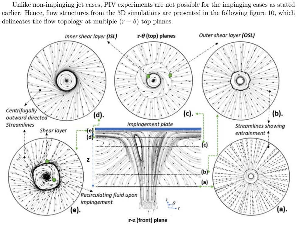
- [Section 3.1 and Fig. 20] The manuscript contains a direct contradiction about whether PIV was possible for impinging cases. Section 3.1 states: 'Unlike non-impinging jet cases, PIV experiments are not possible for the impinging cases as stated earlier.' Yet Fig. 20 and several other figures (Figs. 12, 13, 14, 15, 17, 18, 19, 21, 22, 23) are explicitly captioned as PIV results for impinging cases, and Fig. 20(c) is the sole source cited for the order-of-magnitude TKE comparison in the Conclusion. If the sentence is intended to mean only that top-plane (r-theta) PIV is impossible, that restriction must be stated explicitly. As written, the provenance of the central turbulence data is ambiguous, and the strongest quantitative conclusion rests on an unresolved contradiction.
- [Sections 2.3 and 3.5] The 500-image PIV dataset (recorded at 10 Hz for 50 s) is used to compute second-order turbulence statistics, yet no uncertainty estimates, convergence checks, or effective-sample-size analysis are reported. The POD analysis in Section 3.6 shows large-scale, energetic coherent structures, indicating that the flow is highly unsteady and that 500 snapshots may not be sufficient to converge TKE, Reynolds shear stress, and RMS velocity, especially in the strong-shear near-wall region. The order-of-magnitude difference between H/D = 2 and H/D = 3 in Fig. 20 cannot be distinguished from sampling noise without a split-sample check, bootstrap uncertainty, or an estimate of the number of independent samples. This is a load-bearing issue because the paper's main conclusion depends entirely on this comparison.
- [Section 3.5.1, TKE definition] The paper plots TKE from 2D-PIV data in Fig. 20 without stating how TKE is defined. Two-component PIV measures only the in-plane fluctuations u' and v'; the full TKE, k = 0.5(u'^2+v'^2+w'^2), also requires the out-of-plane (azimuthal) fluctuation w'. The authors acknowledge in their discussion of the Reynolds stress tensor that w'w' 'cannot be shown for the PIV experimental case, which had limitations.' The manuscript must specify whether the TKE values in Fig. 20 use only the two measured components, whether an isotropy assumption is applied, or whether some other approximation is used. The absence of this definition affects the magnitude and possibly the relative ordering of the TKE comparison, and it is essential for the quantitative claim of an order-of-magnitude increase.
minor comments (5)
- [Eq. (6)] Equation (6) appears to have an algebraic error: the Boussinesq approximation should read -rho u'_i u'_j = 2 mu_t S_ij - (2/3) rho k delta_ij, but the strain-rate tensor S_ij is missing on the right-hand side as printed.
- [Section 3.6 and Fig. 26] The text says 'Fig.25 shows the percentage modal energy plotted at different modes,' but the percentage modal energy is displayed in Fig. 26, not Fig. 25. Please correct the cross-reference.
- [Fig. 13 caption] The caption for Fig. 13 reads 'free jet (impingement)' for the radial velocity profiles; this should presumably read 'impinging jet' to match the other impingement-case figures.
- [Section 2.5, validation scope] The validation plots for the impinging case (Figs. 7 and 8) cover only mean axial and radial velocities at one condition (H/D = 3, Re = 23000). No validation of turbulent statistics from the RANS model is provided, so the computational results should not be used as a proxy for the PIV turbulence data without an explicit caveat.
- [General] There are numerous typographical and grammatical issues, including 'interms,' 'Reynold's stress,' and inconsistent use of '450' for '45°' in several figure captions. A careful language edit is recommended.
Circularity Check
No circular derivation: the central turbulence comparison is an independent PIV measurement, and the self-citations to prior work only supply geometry and grid provenance.
full rationale
The paper's central claim—order-of-magnitude higher near-wall TKE for H/D<=2—is an experimental observation from front-plane 2D-PIV, not a fitted parameter renamed as a prediction and not an equation-level reduction to its own inputs. The RANS results are validated against the present PIV data (Figs. 5-8) rather than calibrated to force the turbulence conclusion. Self-citations to Chandra et al. 2023 in Sections 2.1 and 2.4 establish the swirler geometry, computational domain, and grid-independence; these are provenance for the numerical setup and are not the load-bearing support for the measured turbulence statistics, so under Rule 4 they do not constitute circularity. The ambiguous sentence in Section 3.1 that 'PIV experiments are not possible for the impinging cases' appears to refer to top-plane r-theta imaging due to laser-sheet scattering from the acrylic plate (Section 2.5), while front-plane impingement PIV is used in Figs. 7, 8, and 20; if read literally it is a data-provenance inconsistency. The related absence of reported convergence or uncertainty checks for the 500-image PIV statistics is a statistical-support concern, not a circular-derivation concern. No self-definitional step, fitted-input-called-prediction step, self-citation-forced conclusion, or renamed known result is exhibited in the paper, so the circularity score is 0.
Assumptions & free parameters
assumptions (3)
- domain assumption RANS equations with linear eddy-viscosity (Boussinesq) closure adequately reproduce the turbulent swirl impingement flow.
- domain assumption The v2-f computational results are trustworthy in regions where PIV cannot measure, especially near the impingement plate and in the r-theta planes.
- domain assumption 500 PIV double-frame snapshots at 10 Hz are sufficient to converge mean and second-order turbulent statistics.
Cite this review
Pith. "Pith review of On the flow topology of swirl jets upon impingement." pith.science (2026). https://pith.science/paper/KIPU3NK2
@misc{pith2026250523203,
  author       = {Pith},
  title        = {Pith review of: On the flow topology of swirl jets upon impingement},
  year         = {2026},
  howpublished = {\url{https://pith.science/paper/KIPU3NK2}},
  note         = {Machine review of arXiv:2505.23203}
}
abstract
Jet impingement enhances heat transfer and is characterised by the complex flow patterns formed when a jet impacts a plate aligned normal to it. While traditional round jet impingement has been extensively studied to understand flow and associated heat transfer, there is still room for research in investigating flow structures in swirl jet impingement. This paper focuses on the flow topology of swirl jets generated by a 45-degree vane swirler, impinging on a flat plate studied at dimensionless jet-plate distances (H/D=1-4) and Reynolds numbers (Re = 16600 and 23000). The flow structures, mean velocity components, and turbulence characteristics are presented using a 2D Particle Image Velocimetry (PIV) experiment at the front and top planes. Furthermore, results from the 3D numerical simulations are presented to support the results where the PIV study had experimental limitations. The effect of impingement distance or jet-plate distance on the mean flow properties and turbulence parameters is discussed. A Proper Orthogonal Decomposition (POD) analysis has been performed to understand the dominant coherent structures in different cases of impingement distance. We show that the turbulence parameters are more pronounced at smaller jet-plate distances $(H/D \leq 2)$, which could explain the enhanced heat transfer for these jets.
Figures


Figures from the paper (28 more)





Reference graph
Works this paper leans on
-
[1]
recirculation zone) are also shown
which is analogous to a shear layer demarcating the regions of positive velocity from the negative velocity region (i.e. recirculation zone) are also shown. 13 Figure 16: Computed near wall azimuthal velocity profiles at Re=23000 and the effect of H/D on its magnitude is depicted at H/D = 2 and 3. The data are plotted for 2 radial locations L-1 and L-2 wh...
-
[2]
indicating zero axial velocity has been marked for each case. 3.4 Effect of jet-plate distance(H/D) on the velocity The effect of H/D on the velocity components at far and near field to the plate is understood by plotting the velocity components at 2 locations (a). centre of the FOV (z = 45mm or H/D = 1.5) (b). Near the impingement plate (z = -5 mm from t...
work page 1978
-
[3]
Martin H, Heat and Mass Transfer between Impinging Gas Jets and Solid Surfaces, Advances in Heat Transfer,13 (1977), 1-60
work page 1977
-
[4]
R.J. Goldstein, A.I. Behbahani, Impingement of a circular jet with and without cross flow, Int. J. Heat Mass Transf. 25(1982), 1377-1382
work page 1982
-
[5]
Donaldson C. duP, Snedeker RS. A study of free jet impingement. Part 1. Mean properties of free and impinging jets. Journal of Fluid Mechanics. 1971;45(2):281-319
work page 1971
-
[6]
Gardon, R. & Akfirat, J. C., The role of turbulence in determine the heat transfer characteris- tics of impinging jets, Int. J. Heat Mass Transf. 8 (1965), 1261-1272
work page 1965
-
[7]
Cooper, D., Jackson, D. C., Launder B. E. and Liao G. X. 1993 Impinging jet studies for tur- bulence model assessment – I. Flow-field experiments. Int. J. Heat mass Transfer 36 (10), 2675-2684
work page 1993
-
[8]
M. Hadziabdic, K. Hanjalic, Vortical structures and heat transfer in a round impinging jet, J. Fluid Mech. 596 (2008) 221–260
work page 2008
Show all 30 references
-
[9]
Nicholas Syred, A review of oscillation mechanisms and the role of the precessing vortex core (PVC) in swirl combustion systems, Progress in Energy and Combustion Science, Volume 32, Issue 2, 2006, Pages 93-161
2006
-
[10]
& Hargrave, G
Fairweather, M. & Hargrave, G. K. 2002 Experimental investigation of an axisymmetric, im- pinging turbulent jet. 1. Velocity field. Experiments in Fluids 33, 464-471
2002
-
[11]
Gallaire, J.-M
F. Gallaire, J.-M. Chomaz; The role of boundary conditions in a simple model of incipient vortex breakdown. Physics of Fluids 1 February 2004; 16 (2): 274–286
2004
-
[12]
D Lytle, B.W Webb (1994), Air jet impingement heat transfer at low nozzle-plate spacings, Int J Heat and Mass Transfer, 37.12, 1687-1697
1994
-
[13]
Flow field evolution and entrainment in a free surface plunging jet
Hassan, Syed Harris, Guo, Tianqi, and Vlachos, Pavlos P. (2019). “Flow field evolution and entrainment in a free surface plunging jet”. Phys. Rev. Fluids 4 (10),104603
2019
-
[14]
M. A. Herrada, C. Del Pino, J. Ortega-Casanova; Confined swirling jet impingement on a flat plate at moderate Reynolds numbers. Physics of Fluids 1 January 2009; 21 (1): 013601
2009
-
[15]
G., A Swirling Round Turbulent Jet: 1—Mean-Flow Measurements
Rose, W. G., A Swirling Round Turbulent Jet: 1—Mean-Flow Measurements. ASME. J. Appl. Mech. December 1962; 29(4): 615–625
1962
-
[16]
V., and Singh, P
Ekkad, S. V., and Singh, P. (April 21, 2021). ”A Modern Review on Jet Impingement Heat Transfer Methods.” ASME. J. Heat Transfer. June 2021;143(6):064001
2021
-
[17]
Isothermal coherent structures and turbulent flow produced by a gas turbine combustor lean pre-mixed swirl fuel nozzle
G´ omez-Ram ´ ırez, David et al. “Isothermal coherent structures and turbulent flow produced by a gas turbine combustor lean pre-mixed swirl fuel nozzle.” Experimental Thermal and Fluid Science 81 (2017): 187-201. 26
2017
-
[18]
Alekseenko, Artur V
Sergey V. Alekseenko, Artur V. Bilsky, Vladimir M. Dulin, Dmitriy M. Markovich, Experi- mental study of an impinging jet with different swirl rates, Int J Heat and Fluid Flow, 28(6), 1340-1359
-
[19]
Liang Xu, Tao Yang, Yanhua Sun, Lei Xi, Jianmin Gao, Yunlong Li, Jibao Li, Flow and heat transfer characteristics of a swirling impinging jet issuing from a threaded nozzle, Case Studies in Thermal Engineering, Volume 25, 2021, 100970, https://doi.org/10.1016/j.csite.2021.100970
2021
-
[20]
L. F. G. Geers, M. J. Tummers, K. Hanjali´ c; Particle imaging velocimetry-based identifica- tion of coherent structures in normally impinging multiple jets. Physics of Fluids 2005; 17 (5): 055105
2005
-
[21]
L. F. G. Geers, M. J. Tummers, K. Hanjali´ c Wall imprint of turbulent structures and heat transfer in multiple impinging jet arrays. Journal of Fluid Mechanics. 2006; 546:255-284
2006
-
[22]
G., Tummers, M
Geers, F. G., Tummers, M. J. & Hanjalic, G. K. 2004 Experimental investigation of impinging jet arrays. Experiments in Fluids 36, 946-958
2004
-
[23]
El-Genk, Heat transfer of an impinging jet on a flat surface, International Journal of Heat and Mass Transfer, Volume 37, Issue 13, 1994, 1915-1923
Lianmin Huang, Mohamed S. El-Genk, Heat transfer of an impinging jet on a flat surface, International Journal of Heat and Mass Transfer, Volume 37, Issue 13, 1994, 1915-1923
1994
-
[24]
On the dynamics of the large-scale structures in round impinging jets
Hall JW, Ewing D. On the dynamics of the large-scale structures in round impinging jets. Journal of Fluid Mechanics. 2006; 555:439-458
2006
-
[25]
Three-dimensional vortex breakdown in swirling jets and wakes: direct numerical simulation
Ruith MR, Chen P, Meiburg E, Maxworthy T. Three-dimensional vortex breakdown in swirling jets and wakes: direct numerical simulation. Journal of Fluid Mechanics. 2003; 486:331-378
2003
-
[26]
The structure of vortex breakdown
Leibovich, Sidney. “The structure of vortex breakdown.” Annual Review of Fluid Mechanics 10 (1978): 221-246
1978
-
[27]
Three-dimensional organization and dynamics of vortices in multichannel swirling jets
Ianiro A, Lynch KP, Violato D, Cardone G, Scarano F. Three-dimensional organization and dynamics of vortices in multichannel swirling jets. Journal of Fluid Mechanics. 2018; 843:180-210
2018
-
[28]
Tummers, Jeroen Jacobse, Sebastiaan G.J
Mark J. Tummers, Jeroen Jacobse, Sebastiaan G.J. Voorbrood, Turbulent flow in the near field of a round impinging jet, Int J Heat and Mass Transfer, 54, Issues 23–24, 2011, 4939-4948
2011
-
[29]
Three-dimensional coherent structures in a swirling jet undergoing vortex breakdown: stability analysis and empirical mode construction
Oberleithner K, Sieber M, Nayeri CN, et al. Three-dimensional coherent structures in a swirling jet undergoing vortex breakdown: stability analysis and empirical mode construction. Jour- nal of Fluid Mechanics. 2011; 679:383-414
2011
-
[30]
Chandra, Pratikash P
Premchand V. Chandra, Pratikash P. Panda, Pradip Dutta, Flow and heat transfer character- istics of an impinging jet augmented with swirl, Int Comm Heat and Mass Transfer, 149, 2023, 107121 27
2023
Reviewed August 7, 2026 · model on record in the stance chip above.
Discussion (0). Sign in to comment.