REVIEW 4 major objections 5 minor 30 references
The Coupling Effect of Sensing Targets on the Environment for 3GPP ISAC Channels: Observation, Modeling, and Validation
T0 review · 4 major / 5 minor · reviewed 2026-08-07 · deepseek-v4-flash
Pith's one-line read The paper proposes a coupled ISAC channel model where a sensing target both blocks existing multipaths and rescales them by a forward-scattering factor, and reports it matches 105 GHz indoor-factory measurements far better than additive…
desk verdict Useful ISAC channel model with a solid LoS validation but an in-sample NLoS validation; worth peer review with a required held-out check. read the letter →
The pith
A machine-rendered reading of the paper's core claim, the machinery that carries it, and where it could break.
The reading
What carries the argument
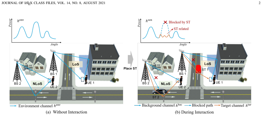
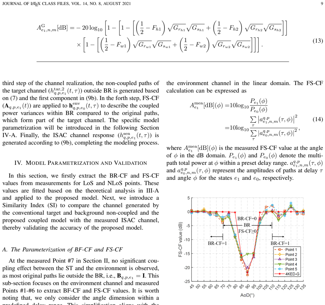
The load-bearing object is the multiplicative decomposition in Eq. (8), $\tilde{\mathbf{B}}_{q,p,e_1}(t) \cdot \mathbf{A}_{q,p,e_1}(t) \cdot \mathbf{h}^{\mathrm{env}}_{q,p,e_0}(t,\tau)$, where $\tilde{\mathbf{B}}$ is the inverse of the boolean blockage-region vector and $\mathbf{A}$ is the forward-scattering factor vector. It converts the abstract idea of coupling into an operation that can be applied to any GBSM-generated environment channel: delete blocked paths, rescale the rest, and add non-coupled target paths through the cascaded Tx-ST-Rx links. The FS-CF values are grounded in the Fresnel-Kirchhoff diffraction integral and the 4KED-G approximation, so that in open LoS geometries the factor can be computed analytically rather than fitted.
What would settle it
A measurement with delay-angle resolution fine enough to resolve individual paths inside the blockage region: if any newly generated coupled path appears at a delay or angle offset larger than the resolution cell from any original environmental path, the multiplicative rescaling of Eq. (8) is falsified. A second check is to fit the FS-CF normal distribution at one NLoS point and validate at an independent NLoS point; if the similarity gain disappears, the distribution is an in-sample artifact.
Extended reading notes
Core claim
The central claim is that the ISAC channel can be written as the environment channel plus a target channel, with the coupling between them expressed by two per-path parameters applied multiplicatively to the pre-existing environmental paths (Eq. (8)): the BR-CF (a boolean that is 0 inside the blockage region, deleting the path) and the FS-CF (a nonnegative amplitude factor that rescales that same path when waves bend around the target). Under line-of-sight conditions the measured FS-CF values match the four-knife-edge diffraction model with antenna gain (4KED-G), while under non-line-of-sight conditions they are statistically described by a normal distribution. The paper's validation shows that generating the ISAC channel this way reproduces the measured power-angle-delay profile more faithfully than directly superimposing target and background channels.
Load-bearing premise
The load-bearing premise is that the target's coupling with the environment can be fully represented by multiplying the existing environmental path coefficients by a blockage flag and a forward-scattering gain (Eq. (8)), rather than by creating genuinely new paths with shifted delays or angles; the NLoS validation additionally uses the normal distribution fitted at Point #6 to score Point #6 itself.
Editorial extensions
If this is right
- In LoS scenarios, the FS-CF can be precomputed from the target geometry with the 4KED-G model, so no per-scenario fitting is needed for open environments.
- Standard 3GPP GBSM environment-channel generation can be reused as-is; the coupling effect is added as a post-processing step on path coefficients.
- The non-coupled model overestimates received power in the blocked angular region; the coupled model removes roughly 20 dB of excess power in the LoS measurements.
- The same two-factor structure applies at cluster level as well as path level, meaning the model can be simplified when only cluster statistics are needed.
- The coupled model raises the similarity index by about 30 percentage points in LoS and about 5 percentage points in NLoS, which is the quantitative claim a standardization body would evaluate.
Reading between the lines
- If the multiplicative coupling holds, tracking a moving target amounts to updating two scalar fields per path (blockage flag and forward-scattering gain), so a time-varying ISAC channel could be generated cheaply from a static environment model.
- The measured 40-degree blockage-region width exceeds the target's roughly 7-8 degree angular size, suggesting the region depends on antenna beamwidth and target size; a natural extension is a parametric BR formula that would let the model generalize outside the measured geometry.
- Because FS-CF is defined as a power ratio in the same delay-angle cell, the model implicitly assumes the coupled path is indistinguishable from the original path in delay-angle; high-resolution arrays could test this assumption and, if it fails, motivate a hybrid model that also shifts rays.
- The NLoS normal distribution for FS-CF was fitted and evaluated at the same point; applying it to an untouched measurement point would strengthen the standardization case.
Editorial analysis
A structured set of objections, weighed in public.
Referee Report
Summary. The paper presents a measurement campaign at 105 GHz in an indoor factory scenario, with an automated guided vehicle as a sensing target, and proposes a coupled ISAC channel model that extends the 3GPP GBSM by introducing a Blockage-Region Coupling Factor (BR-CF) and a Forward-Scattering Coupling Factor (FS-CF). The model represents the target-environment coupling by rescaling or deleting existing environment paths within a blockage region and superposing newly generated non-coupled target paths. The authors observe that the measured LoS FS-CF follows a 4KED-G diffraction model, while the NLoS FS-CF is fitted to a normal distribution. Validation is performed by comparing the similarity index (SI) between measured and simulated channels at one LoS point and one NLoS point, reporting approximately 30% and 5% higher SI for the proposed coupled model relative to a non-coupled superposition.
Significance. The paper addresses a genuine and timely problem: the coupling between sensing targets and the surrounding environment is typically ignored in ISAC channel models, and the proposed BR-CF/FS-CF framework is a reasonable and standards-aligned way to incorporate it. The LoS validation is a notable strength: the measured FS-CF values are compared with the parameter-free 4KED-G model and show good agreement, which lends physical credibility to the proposed parameterization. The measurement campaign itself, with detailed PADP observations at 105 GHz, is a useful contribution to the sparse ISAC channel measurement literature. However, the NLoS validation is compromised by in-sample fitting, and the overall validation rests on only one point per condition with boundaries chosen from the same data, so the quantitative superiority claim is not yet firmly established.
major comments (4)
- [§IV-A2 and §IV-B] The NLoS validation is in-sample and therefore does not support the claimed predictive advantage. In §IV-A2, the FS-CF normal distribution with mean 0.066 dB and variance 0.253 dB^2 is fitted to 360 samples taken exclusively at Point #6 (20 snapshots, 9 angles, 2 delay ranges). In §IV-B, the simulated Point #6 channel is generated using exactly these fitted FS-CF values and then compared with the measured Point #6 channel via the SI. The same data determine the model parameters and score the model, so the ~5% SI increase in Table II may reflect fitting rather than a genuine coupling-model effect. The paper should either validate on a held-out point (e.g., a different NLoS location) or explicitly rephrase the NLoS result as a fit-quality assessment rather than a validation.
- [§IV-A2 vs. §IV-B] There is an internal inconsistency in the BR boundary for Point #6: §IV-A2 states that the BR is defined as 120° to 150° based on Fig. 6, whereas the validation paragraph in §IV-B says that BR-CF values are set to 0 within 110° to 150°. This discrepancy makes the parameterization range ambiguous and prevents the reader from reproducing the NLoS simulation. The authors must correct the boundary value and justify which range is used in the SI computation.
- [§IV-A and §IV-B] The BR angular boundaries for both LoS (70°–110°) and NLoS (120°–150° or 110°–150°) are selected from the same measured PAS that is subsequently used for validation. This introduces a selection bias: the power-variation region is identified from the data, then the model is tuned to remove exactly that region. The LoS case is less vulnerable because the FS-CF values come from the theoretical 4KED-G model, but the BR boundaries themselves are data-derived. The authors should either derive the boundaries from independent geometric considerations (e.g., ST angular extent plus antenna beamwidth) or report the sensitivity of the SI to the chosen boundaries.
- [§IV-B, Eq. (15)] The SI computation is not fully specified, which undermines the reproducibility of the quantitative claims in Table II. The paper refers to a 'predefined delay range' and states that only paths within 75 m are depicted, but the exact delay windows and angular bins used in Eq. (15) for Points #2 and #6 are not given. Without these details, the reader cannot reproduce the SI values or determine whether the reported 30% and 5% gains are sensitive to the chosen integration range.
minor comments (5)
- [§III-A] There are repeated typographical errors in the terminology: 'BF-CF' appears instead of 'BR-CF' in several places (e.g., the sentence following Eq. (6) and the header of §IV-A), and 'Forward-Sattering' appears in §III-A.
- [§IV-A2] The normality of the NLoS FS-CF distribution is asserted based on the CDF in Fig. 12(b), but no goodness-of-fit test (e.g., Kolmogorov-Smirnov) or confidence interval for the fitted mean/variance is reported. Adding a quantitative fit test would strengthen the statistical claim.
- [Table II and §V] The statement that the coupled model achieves 'approximately 30% and 5% higher similarity' is ambiguous: for LoS, the SI increases are about 30 percentage points (e.g., 48.99% to 79.02% in SI τ,ϕ), while for NLoS, the increases are 2.72, 4.92, and 5.26 percentage points for the three SI variants. The paper should specify whether the reported gains are percentage points or relative improvements, and the 5% figure for NLoS appears to be closer to 4% on average.
- [References] Reference [4] is incomplete: it lacks a venue, arXiv identifier, or publication year details. Please provide the full bibliographic information.
- [§IV-A1] The statement that the FS-CF values at Point #1 align with the 4KED-G model 'with only minor deviations' is based on visual inspection of Fig. 11. A quantitative error metric (e.g., root-mean-square error between the measured and 4KED-G curves) would be more persuasive.
Circularity Check
NLoS validation is in-sample: FS-CF is fitted at Point #6 and reused to simulate Point #6; the LoS BR-CF is also extracted from the validated points, so the claimed gains are partly fitting.
-
fitted input called prediction
[Section IV-A2 (ST coupling with environmental NLoS paths) and Section IV-B (The Accuracy of the Proposed Channel Model), Table II NLoS rows.]
"To further model the FS-CF values, we conduct a statistical analysis on 20 measured snapshots across the BR ... resulting in 360 samples (9 angles × 2 ranges × 20 snapshots). ... this distribution has a mean of 0.066 dB and a variance of 0.253 dB2, providing a preliminary quantification for FS-CF values under NLoS conditions. ... The simulated ISAC channel generated using the proposed coupled model incorporates BR-CF values of the effective multipaths set to 0 within 110°-150° and the preset delay range. The FS-CF values follow the normal distribution extracted in Section IV-A."
The NLoS FS-CF distribution is fit to 360 samples collected at Point #6 and then reused in the simulation of Point #6, whose measured channel is the reference for the SI gain (~5%). The validation therefore compares Point #6 against a simulation whose stochastic FS-CF parameters were estimated from Point #6 itself. This is an in-sample fit, not an independent prediction; the 5% improvement could be produced by matching the measured power statistics of the same point. The discrepancy between the 120°-150° BR used for parameterization and the 110°-150° BR used in validation further blurs the parameterization-validation split.
-
fitted input called prediction
[Section IV-A1 (ST coupling with environmental LoS paths) and Section IV-B (The Accuracy of the Proposed Channel Model), Table II LoS rows.]
"As shown in Fig. 5 of Section II-B, the BR is defined as 70° to 110°. Within this range, the BR-CF values are set to 0, while values less than 70° or greater than 110° are set to 1. ... The model parameters are derived from the results in Section IV-A), where, within the 70°-110° angular BR and the predefined delay range, the BR-CF values for effective multipaths are set to 0 ... The results indicate that the proposed ISAC channel model enhances similarity to the measured ISAC channel by approximately 30% across all dimensions compared to the non-coupled model."
For the LoS claim (~30% gain), the BR-CF mask is not predicted from geometry but read off the measurements: Section IV-A1 defines BR as 70°-110° from Fig. 5, and Section IV-B inserts this mask at Point #2 (one of the same LoS points) before computing SI. Removing the measured blocked sector will by construction raise agreement with the measured channel relative to the non-coupled model. The FS-CF values are independently supported by the 4KED-G model, so the LoS comparison is only partly circular, but the headline 30% gain is not a fully out-of-sample validation.
full rationale
The paper's central physical contribution—the observed coupling effect and the multiplicative decomposition in Eq. (8)—is not itself circular: Eq. (8) is an explicit modeling ansatz, not derived from the target result, and the LoS FS-CF comparison against the parameter-free 4KED-G model provides independent support. The self-citations ([2], [4], [20], [24], [25]) are used for context and do not carry the derivation. The circularity is concentrated in the validation protocol: both headline gains are scored on points whose key coupling parameters (BR-CF, and for NLoS FS-CF) were extracted from those same points. The NLoS 5% gain is the clearest case because the fitted normal distribution at Point #6 is reused to generate Point #6. The LoS 30% gain is partly protected by the theoretical FS-CF, but the BR-CF mask is still in-sample. This warrants a partial-circularity score of 6 rather than higher, because the model itself, the observations, and the LoS FS-CF theory have independent content; the paper's predictive claim, however, is overstated by the in-sample validation.
Assumptions & free parameters
free parameters (5)
- LoS BR angular boundaries =
70 to 110 degrees
- NLoS BR angular boundaries =
120 to 150 degrees (Section IV-A2); 110 to 150 degrees (Section IV-B)
- NLoS FS-CF distribution mean =
0.066 dB
- NLoS FS-CF distribution variance =
0.253 dB^2
- Predefined delay ranges for SI calculation =
LoS: 75 to 89 ns; NLoS: 88 to 94 ns and 107 to 134 ns
assumptions (5)
- domain assumption The target/background channel decomposition agreed in 3GPP RAN #116 (target channel and background channel) is a valid basis for ISAC channel modeling.
- domain assumption The environment channel measured without the target stays valid when the target is present, except for a binary blockage flag and a scalar forward-scattering factor.
- domain assumption The 4KED-G knife-edge diffraction model (perfectly absorbing thin plate, beta0 approximately 180 degrees, four edge centers) describes forward scattering from the metal-box target at 105 GHz.
- standard math Fresnel-Kirchhoff diffraction integral (Eq. 10) is applicable with the ST surface perpendicular to the L1-L2 line and beta0 approximately 180 degrees.
- ad hoc to paper NLoS FS-CF values are Gaussian distributed.
Cite this review
Pith. "Pith review of The Coupling Effect of Sensing Targets on the Environment for 3GPP ISAC Channels: Observation, Modeling, and Validation." pith.science (2026). https://pith.science/paper/AQRFEW5N
@misc{pith2026250600480,
  author       = {Pith},
  title        = {Pith review of: The Coupling Effect of Sensing Targets on the Environment for 3GPP ISAC Channels: Observation, Modeling, and Validation},
  year         = {2026},
  howpublished = {\url{https://pith.science/paper/AQRFEW5N}},
  note         = {Machine review of arXiv:2506.00480}
}
read the original abstract
Integrated Sensing And Communication (ISAC) has been identified as a key 6G application by ITU and 3GPP, with standardization efforts already underway. Sensing tasks, such as target localization, demand more precise characterization of the sensing target (ST) in ISAC channel modeling. The ST couples complexly with environmental scatterers, potentially blocking some multipaths and generating new ones, resulting in power variations compared to the original channel. To accurately model this effect, this paper proposes a coupled ISAC channel model based on measurements and validates it through similarity analysis between simulated and measured channels. In this work, we first conduct ISAC channel measurements in an indoor factory scenario at 105 GHz, where the multipath power variations caused by the ST's interaction with the environment are clearly observed. Then, we propose an ISAC channel modeling framework that incorporates two novel parameters: the Blockage-Region Coupling Factor (BR-CF) and the Forward-Scattering (FS)-CF, which characterize the spatial region and intensity of the coupling effect, respectively. Finally, the proposed model is validated through similarity comparison with measured data, demonstrating higher accuracy for both LoS and NLoS scenarios compared to the non-coupled model. This realistic ISAC channel model provides an effective framework for capturing the ST-environment coupling effect, supporting the design and evaluation of ISAC technologies.
Figures


Figures from the paper (11 more)




Reference graph
Works this paper leans on
-
[1]
Vision, requirements and network architecture of 6G mobile network beyond 2030,
G. Liu, Y . Huang, N. Li, J. Dong, J. Jin, Q. Wang, and N. Li, “Vision, requirements and network architecture of 6G mobile network beyond 2030,” China Commun. , vol. 17, no. 9, pp. 92–104, Sep. 2020
work page 2020
-
[2]
A shared cluster-based stochastic channel model for integrated sensing and communication systems,
Y . Liu, J. Zhang, Y . Zhang, Z. Yuan, and G. Liu, “A shared cluster-based stochastic channel model for integrated sensing and communication systems,” IEEE Trans. V eh. Technol., 2023
work page 2023
-
[3]
RP-234016, New SID: Study on channel modelling for Integrated Sensing And Communication (ISAC) for NR, 3GPP TSG RAN #102, December 11th – 15th, 2023
work page 2023
-
[4]
Latest progress for 3GPP ISAC channel modeling standardization,
Y . Zhang, J. Zhang, Y . Pei, Y . Liu, and T. Jiang, “Latest progress for 3GPP ISAC channel modeling standardization,” 2024
work page 2024
-
[5]
IEEE 802.11 ad-based radar: An approach to joint vehicular communication-radar system,
P. Kumari, J. Choi, N. Gonz ´alez-Prelcic, and R. W. Heath, “IEEE 802.11 ad-based radar: An approach to joint vehicular communication-radar system,” IEEE Trans. V eh. Technol., vol. 67, no. 4, pp. 3012–3027, Nov. 2017
work page 2017
-
[6]
Y . Liu, B. Zhang, D. Guo, H. Wang, and G. Ding, “Joint precoding design and location optimization in joint communication, sensing and computing of UA V systems,”IEEE Trans. Cogn. Commun. Netw. , 2023
work page 2023
-
[7]
A survey on fundamental limits of integrated sensing and communication,
A. Liu, Z. Huang, M. Li, Y . Wan, W. Li, T. X. Han, C. Liu, R. Du, D. K. P. Tan, J. Lu et al., “A survey on fundamental limits of integrated sensing and communication,” IEEE Commun. Surveys Tuts. , vol. 24, no. 2, pp. 994–1034, Feb. 2022
work page 2022
-
[8]
An overview of signal processing techniques for joint communication and radar sensing,
J. A. Zhang, F. Liu, C. Masouros, R. W. Heath, Z. Feng, L. Zheng, and A. Petropulu, “An overview of signal processing techniques for joint communication and radar sensing,” IEEE J. Sel. Topics Signal Process. , vol. 15, no. 6, pp. 1295–1315, Sep. 2021
work page 2021
Show all 30 references
-
[9]
Small target tracking in satellite videos using background compensation,
Y . Wang, T. Wang, G. Zhang, Q. Cheng, and J.-q. Wu, “Small target tracking in satellite videos using background compensation,” IEEE Trans. Geosci. Remote Sens. , vol. 58, no. 10, pp. 7010–7021, 2020
2020
-
[10]
Spatial structure matching based DoA estimation and tracking for integrated sensing and communication massive MIMO OFDM system,
K. Xu, X. Xia, C. Li, G. Hu, Q. Su, and W. Xie, “Spatial structure matching based DoA estimation and tracking for integrated sensing and communication massive MIMO OFDM system,” IEEE Trans. Cogn. Commun. Netw., 2023
2023
-
[11]
Three-dimensional fading channel models: A survey of elevation angle research,
J. Zhang, C. Pan, F. Pei, G. Liu, and X. Cheng, “Three-dimensional fading channel models: A survey of elevation angle research,” IEEE Commun. Mag. , vol. 52, no. 6, pp. 218–226, 2014
2014
-
[12]
Spatial non- stationary near-field channel modeling and validation for massive MIMO systems,
Z. Yuan, J. Zhang, Y . Ji, G. F. Pedersen, and W. Fan, “Spatial non- stationary near-field channel modeling and validation for massive MIMO systems,” IEEE Trans. Antennas Propag. , vol. 71, no. 1, pp. 921–933, Nov. 2022
2022
-
[13]
On the fundamental tradeoff of integrated sensing and communications under gaussian channels,
Y . Xiong, F. Liu, Y . Cui, W. Yuan, T. X. Han, and G. Caire, “On the fundamental tradeoff of integrated sensing and communications under gaussian channels,” IEEE Trans. Inf. Theory , vol. 69, no. 9, pp. 5723– 5751, 2023
2023
-
[14]
From torch to projector: Fundamental tradeoff of integrated sensing and communications,
Y . Xiong, F. Liu, K. Wan, W. Yuan, Y . Cui, and G. Caire, “From torch to projector: Fundamental tradeoff of integrated sensing and communications,” IEEE BITS Inf. Theory Mag. , 2024
2024
-
[15]
Location sensing and beamforming design for IRS-enabled multi-user ISAC systems,
Z. Yu, X. Hu, C. Liu, M. Peng, and C. Zhong, “Location sensing and beamforming design for IRS-enabled multi-user ISAC systems,” IEEE Trans. Signal Process. , vol. 70, pp. 5178–5193, 2022
2022
-
[16]
Code-division OFDM joint communication and sensing system for 6G machine-type communication,
X. Chen, Z. Feng, Z. Wei, P. Zhang, and X. Yuan, “Code-division OFDM joint communication and sensing system for 6G machine-type communication,” IEEE Internet Things J. , vol. 8, no. 15, pp. 12 093– 12 105, Feb. 2021
2021
-
[17]
R1-2406107, ISAC Channel Measurements and Modeling, 3GPP TSG RAN WG1 #118, Aug 19th – Aug 23th, 2024
2024
-
[18]
Toward 5G NR high-precision indoor positioning via channel frequency response: A new paradigm and dataset generation method,
K. Gao, H. Wang, H. Lv, and W. Liu, “Toward 5G NR high-precision indoor positioning via channel frequency response: A new paradigm and dataset generation method,” IEEE J. Sel. Areas Commun. , vol. 40, no. 7, pp. 2233–2247, 2022
2022
-
[19]
Chair Notes, 3GPP TSG RAN WG1 #116, February 26th–March 1st, 2024
2024
-
[20]
How to extend 3D GBSM to integrated sensing and communication channel with sharing feature?
Y . Liu, J. Zhang, Y . Zhang, H. Gong, T. Jiang, and G. Liu, “How to extend 3D GBSM to integrated sensing and communication channel with sharing feature?” IEEE Wireless Commun. Lett. , 2024
2024
-
[21]
Integrated sensing and communication channel modeling and measurements: Requirements and methodologies toward 6G standardization,
W. Yang, Y . Chen, N. Cardona, Y . Zhang, Z. Yu, M. Zhang, J. Li, Y . Chen, and P. Zhu, “Integrated sensing and communication channel modeling and measurements: Requirements and methodologies toward 6G standardization,” IEEE V eh. Technol. Mag., 2024
2024
-
[22]
A unified channel model for both communication and sensing in integrated sensing and communication systems,
J. Lou, R. Liu, C. Jiang, X. Han, Z. Han, Q. Yang, and Z. Wang, “A unified channel model for both communication and sensing in integrated sensing and communication systems,” in 2023 IEEE 98th V ehicular Technology Conference (VTC2023-Fall). IEEE, 2023, pp. 1–6
2023
-
[23]
Channel modeling framework for both communications and bistatic sensing under 3GPP standard,
C. Luo, A. Tang, F. Gao, J. Liu, and X. Wang, “Channel modeling framework for both communications and bistatic sensing under 3GPP standard,” IEEE J. Sel. Areas Commun. , 2024
2024
-
[24]
Empirical analysis of sensing channel characteristics and environment effects at 28 GHz,
J. Wang, J. Zhang, Y . Zhang, T. Jiang, L. Yu, and G. Liu, “Empirical analysis of sensing channel characteristics and environment effects at 28 GHz,” in Proc. IEEE Globecom Workshops (GC Wkshps) , Dec. 2022, pp. 1323–1328
2022
-
[25]
An empirical study of ISAC channel characteristics with human target impact at 105 GHz,
W. Chen, Y . Zhang, Y . Liu, J. Zhang, H. Gong, T. Jiang, and L. Xia, “An empirical study of ISAC channel characteristics with human target impact at 105 GHz,” Electronics Lett., vol. 60, no. 17, p. e70017, 2024
2024
-
[26]
Radar handbook,
M. I. Skolnik, “Radar handbook,” 1970
1970
-
[27]
Channel model(s) for 0.5-100 GHz,
“Channel model(s) for 0.5-100 GHz,” 3GPP, Sophia Antipolis Cedex, France, TR 38.901., Jun. 2018. [Online]. Available: www.3gpp.org
2018
-
[28]
Cascaded channel modeling and experimental verification for RIS assisted communication system,
J. Zhang, Y . Zhang, H. Gong, J. Zhang, and L. Tian, “Cascaded channel modeling and experimental verification for RIS assisted communication system,” arxiv preprint arxiv:2412.07356 , 2024
2024 arXiv
-
[29]
Born and E
M. Born and E. Wolf, Principles of optics: electromagnetic theory of propagation, interference and diffraction of light . Elsevier, 2013
2013
-
[30]
Four Knife- Edge Diffraction with antenna gain model for generic blockage mod- elling,
S. Kizhakkekundil, J. Morais, S. Braam, and R. Litjens, “Four Knife- Edge Diffraction with antenna gain model for generic blockage mod- elling,” IEEE Wireless Commun. Lett. , vol. 10, no. 10, pp. 2106–2109, 2021
2021
Reviewed August 7, 2026 · model on record in the stance chip above.
Discussion (0). Sign in to comment.