REVIEW 3 major objections 6 minor 53 references
Heliostat Optical Error Inspection with Polarimetric Imaging Drone
T0 review · 3 major / 6 minor · reviewed 2026-08-07 · deepseek-v4-flash
Pith's one-line read A UAV-mounted polarization camera recovers heliostat mirror edges in two low-contrast scenarios that defeat visible cameras, with success rates above 91 percent and no interruption of field operation.
desk verdict A credible polarimetric-UAV inspection paper whose headline improvement claim is not actually measured against a matched visible-image baseline; the forward model and field data are real, but the success-rate comparison needs a paired experiment. read the letter →
The pith
A machine-rendered reading of the paper's core claim, the machinery that carries it, and where it could break.
The reading
What carries the argument
The load-bearing machinery is the Stokes-parameter description of polarization, with $\mathrm{DoLP}$ (the fraction of light that is linearly polarized) and $\mathrm{AoP}$ (the orientation angle of that polarization) computed from intensity readings through four wire-grid filters at $0^\circ$, $45^\circ$, $90^\circ$, and $135^\circ$. Around this sit three models: Rayleigh scattering for the sky's polarization pattern, a Fresnel reflection Mueller matrix for the clean mirror surface, and the Torrance-Sparrow microfacet model (refractive index $1.45$, half-Gaussian microfacet zenith distribution, uniform azimuth distribution) for the rough ground. The simulation converts these into maps of expected $\mathrm{DoLP}$ difference between adjacent heliostats and $\mathrm{AoP}$ difference between mirror reflection and ground, and the flight path is chosen to maximize those differences. In processing, only images with $\mathrm{DoLP} > 0.2$ on the heliostat reflection are used, and ground-vs-ground contrast is treated as sufficient when the $\mathrm{AoP}$ difference exceeds about $50^\circ$.
What would settle it
Take a heliostat pair whose facet canting has been independently measured, fly the same waypoints on a clear day and again with a light dust layer on the mirrors or over a different ground surface, and compare measured versus predicted DoLP/AoP differences and edge-detection success. If the AoP difference between mirror reflection and real ground falls below roughly 50 degrees, or the DoLP difference between adjacent heliostats below 0.2, while visible contrast is still low, the simulated waypoint maps would be shown to fail in exactly the conditions a real field presents; conversely, if the edge-detection success rates hold with independently verified ground-truth canting, the proof-of-concept becomes a full validation.
Extended reading notes
Core claim
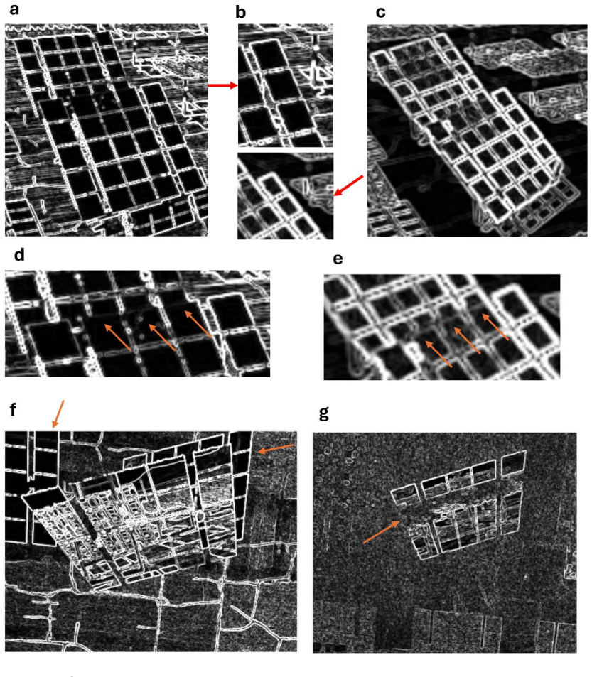
The central discovery is that the polarization pattern of skylight is a free, controllable source of contrast for heliostat edges. Because Rayleigh scattering orders the polarization state across the sky, two neighboring heliostats that look identical in color can reflect skylight with measurably different $\mathrm{DoLP}$, and a mirror's reflection of the ground can differ from the real ground by more than $50^\circ$ in $\mathrm{AoP}$. The paper combines a Rayleigh-scattering model of sky polarization, a Fresnel-based Mueller matrix for clean specular mirror reflection, and a Torrance-Sparrow rough-surface model for the ground, then uses the predicted $\mathrm{DoLP}$ and $\mathrm{AoP}$ difference maps to position the drone. In field tests, Sobel edge detection on polarization images produced clear facet edges where RGB images showed almost no measurable contrast, with a contrast ratio of 5.93 for DoLP images in the sky-vs-sky case. The resulting canting-error estimates for one heliostat's facets stayed within 10 mrad of the ideal design reference, with standard deviations of 3.00 mrad in azimuth and 2.11 mrad in zenith; because no ground-truth canting data were available, the paper treats this as a proof-of-concept rather than validation.
Load-bearing premise
The load-bearing premise is that a clear-sky Rayleigh scattering model plus a clean, specular mirror and a single idealized rough ground material predicts where polarization contrast will actually be high enough for edge detection; if haze, dust, mixed ground surfaces, or soiled mirrors shift the polarization pattern, the planned waypoints may lose contrast and the DoLP > 0.2 gate may reject exactly the images that need analysis.
Editorial extensions
If this is right
- If PIHIM works as reported, any visible-camera inspection method that needs reliable heliostat boundaries can add a polarization camera and recover edges in the cases it currently misses.
- Flight planning can be done from simulation: at the test site, favorable polarimetric contrast was available roughly between 9:30-11:30 and 14:00-16:00, so inspections can be scheduled rather than attempted at arbitrary times.
- The throughput estimate is about 36 heliostats per hour per drone now and 50-100 with upgrades, which would put a 10,000-heliostat field within 100-200 drone-hours, or under a day with roughly 10 drones.
- The same polarization-imaging platform extends to related inspection tasks, including mirror soiling detection and crack detection, without changing the core hardware.
- Combining visible, DoLP, and AoP images is the paper's stated next step, since current polarization sensors' lower resolution limits edge-localization accuracy and therefore canting-error precision.
Reading between the lines
- Beyond the paper: the same skylight-polarization contrast mechanism should transfer to any specular surface viewed against sky or ground reflections, such as solar panels, building facades, or vehicle glazing, wherever a Rayleigh sky model is valid.
- Beyond the paper: the DoLP > 0.2 gate could be inverted into a sensor: rather than discarding low-DoLP frames, an operator could use the measured DoLP drop as a real-time indicator of haze, cloud, or mirror soiling, turning the method's limitation into a diagnostic.
- Beyond the paper: the reported 10-20 degree simulation-to-measurement AoP offset suggests a cheap calibration step, measuring the local ground's polarization response once with the drone and updating the Torrance-Sparrow parameters per field, would sharpen waypoint optimization more than refining the sky model.
- Beyond the paper: the simulation's dependence on sun position means the same framework could be run in reverse on a single polarization image to estimate the sun's position or the heliostat's orientation, offering a possible self-calibration path for existing error-detection pipelines.
Editorial analysis
A structured set of objections, weighed in public.
Referee Report
Summary. The paper presents a UAV-based polarimetric imaging method (PIHIM) for heliostat inspection in concentrating solar power (CSP) fields. The authors develop a forward optical model combining Rayleigh-scattered skylight polarization, Fresnel reflection Mueller matrices, and a Torrance-Sparrow rough-ground model to predict DoLP and AoP contrast in two challenging scenarios: sky-vs-sky (overlapping heliostats) and ground-vs-ground (mirror reflection of ground adjacent to real ground). The model is used to guide UAV waypoint planning. Field tests at the Sandia NSTTF are reported, including DoLP/AoP contrast comparisons, Sobel edge detection examples, and success rates in Table 2 (91.53% for sky-vs-sky, 96.67% for ground-vs-ground). The paper also demonstrates a canting-error calculation on one heliostat, explicitly labeled as a proof-of-concept because no ground-truth canting data were available.
Significance. If the quantitative claims are supported, PIHIM would be a practical complement to existing visible-light UAV inspection methods by adding polarization channels that enhance edge contrast in low-contrast scenes. The paper has notable strengths: the physical forward model is built from standard, reproducible components (Rayleigh scattering, Fresnel Mueller matrices, Torrance-Sparrow BRDF); the field data are real and the authors transparently enumerate limitations of the model, the dataset, and the absence of ground truth; and the proposed combination of visible, DoLP, and AoP images is a sensible direction. However, the headline claim of an 'improved success rate' is not yet quantitatively supported because Table 2 reports success rates only for polarization images, without a matched visible-image baseline for the same image sets, and because the DoLP > 0.2 processing filter is applied without reporting how many images were excluded. These issues are fixable but require additional analysis or a tempering of the claim.
major comments (3)
- [Section 4.3 / Table 2] The success rates of 91.53% and 96.67% are computed only for polarization images, and the manuscript states in Section 4.3 that 'corresponding visible images were not available for every polarimetric image.' Without a matched visible-image baseline for the same image sets and the same success criterion, Table 2 does not support the abstract's claim that PIHIM 'improved the success rate of edge detections.' The qualitative comparisons in Figure 6 are selected examples, not a paired quantitative evaluation. Please report visible-image success rates for the same image sets, or revise the abstract and Section 4.3 to present the improvement as qualitative.
- [Section 5 (Conclusions) and Section 4.3] The paper states that only images with DoLP greater than 0.2 on the heliostat reflection are processed, but Table 2 does not report how many collected images were excluded by this filter or what the success rates would be without it. This post-hoc selection criterion could bias the reported success rates upward, and it simultaneously limits the method's applicability precisely in the cloudy, polluted, or soiled conditions where visible imaging might also fail. Please provide the full data flow: total images captured, number excluded by the DoLP threshold, and success rates with and without the filter.
- [Section 4.2 / Table 1] The Torrance-Sparrow ground model is reported to have simulation-measurement AoP differences of 10–20 degrees, and the paper uses an AoP difference greater than 50 degrees as the criterion for sufficient contrast. A 10–20 degree error can shift a predicted 'good' waypoint into a borderline region. The claim that the model provides 'optimized waypoints' would be strengthened by a sensitivity analysis (for example, how many waypoints remain above the 50-degree threshold when the observed model bias is applied) or by an explicit statement that the model serves as a heuristic for survey flight planning rather than as a precise optimizer. This concern is directly related to the authors' own enumerated model limitations.
minor comments (6)
- [Equation (2)] The AoP formula uses the two-argument inverse tangent implicitly but the text does not specify the quadrant-aware atan2 convention; please state it explicitly to avoid ambiguity in the 0–180 degree range.
- [Section 4.1 / Figure 4f] The text attributes the measured lower DoLP contrast to 'increased scattering events under various weather conditions,' but no atmospheric or weather data are reported; if available, please state the conditions quantitatively or mark the explanation as qualitative.
- [Figure 8 caption] The caption notes that facet numbers with no data points indicate zero calculated canting error; please consider adding the same clarification in the text of Section 4.4, since a reader may otherwise interpret missing markers as missing data rather than zero values.
- [Abstract] The phrase 'significantly enhanced heliostat edge detection success rate' overstates the current evidence given the missing visible baseline; consider using a more cautious formulation such as 'increased edge detection success' with an explicit caveat.
- [References] Reference [7] is missing journal and DOI information; please complete the bibliographic details.
- [Figure 1 caption] The caption contains a duplicated label: 'e, Schematics of system components. e, diagram illustrating the UAV setup.' Please correct the second label (likely 'f').
Circularity Check
No significant circularity: the simulation is a forward physical model compared with field measurements, and the reported success rates are observed data rather than outputs of the model.
full rationale
The paper's derivation chain is not circular. The simulation chain (Rayleigh skylight polarization, Fresnel Mueller-matrix reflection, and Torrance-Sparrow rough-ground reflection) is a forward model built from standard physical laws and literature parameters; it is not fitted to the field measurements it is compared against. In Fig. 4f and Fig. 5e the simulated DoLP/AoP differences are explicitly compared with measured values and found to differ by 10–20 degrees in AoP, so the model is not tuned to reproduce the validation data. The waypoint-planning use of the model does not make the later results circular: Table 2 success rates are empirical judgments on captured polarimetric images, with success defined by whether all facet edges can be identified using the known heliostat geometry, not by whether the simulation predicted them. The canting-error section is also transparently non-circular: the paper states that no ground-truth canting data were available, that the ideal reference is generated by UFACET assuming plano facets and a symmetric paraboloid, and that the reported values are deviations from this ideal design rather than absolute canting errors (Section 4.4 and Conclusions). Self-citations to the authors' prior work [1] appear as motivation, as a prior observation of AoP contrast, and as an 89%-to-96.7% ground-vs-ground comparison, but the central claim of contrast enhancement is independently supported in the present paper by current field images and direct contrast measurements (Michelson contrast near unity for visible versus a 5.93 average contrast ratio for DoLP images in Section 4.3). The absence of a matched visible-image baseline for every polarimetric image is a genuine evidence limitation that the authors acknowledge, but it is a correctness/validation concern, not a circular reduction of the claimed result to its inputs. No equation or reported quantity is equivalent by construction to a fitted parameter or to a self-citation, so no specific circular step can be identified.
Assumptions & free parameters
free parameters (3)
- Half-Gaussian microfacet zenith distribution width
- DoLP processing threshold =
0.2
- Ground refractive index =
1.45
assumptions (4)
- domain assumption Skylight polarization follows the single-scattering Rayleigh model for a given sun position and time.
- domain assumption Reflection from heliostat mirrors is specular and described by Fresnel Mueller matrices with a single refractive index.
- domain assumption Ground reflection is approximated by the Torrance-Sparrow model with microfacets following a half-Gaussian zenith distribution and uniform azimuth distribution.
- domain assumption The skylight polarization pattern is approximately invariant under translation of the origin by several hundred meters.
Cite this review
Pith. "Pith review of Heliostat Optical Error Inspection with Polarimetric Imaging Drone." pith.science (2026). https://pith.science/paper/G637GBSK
@misc{pith2026250602333,
  author       = {Pith},
  title        = {Pith review of: Heliostat Optical Error Inspection with Polarimetric Imaging Drone},
  year         = {2026},
  howpublished = {\url{https://pith.science/paper/G637GBSK}},
  note         = {Machine review of arXiv:2506.02333}
}
read the original abstract
On a Concentrated Solar Power (CSP) field, optical errors have significant impacts on the collection efficiency of heliostats. Fast, cost-effective, labor-efficient, and non-intrusive autonomous field inspection remains a challenge. Approaches using imaging drone, i.e., Unmanned Aerial Vehicle (UAV) system integrated with high resolution visible imaging sensors, have been developed to address these challenges; however, these approaches are often limited by insufficient imaging contrast. Here we report a polarimetry-based method with a polarization imaging system integrated on UAV to enhance imaging contrast for in-situ detection of heliostat mirrors without interrupting field operation. We developed an optical model for skylight polarization pattern to simulate the polarization images of heliostat mirrors and obtained optimized waypoints for polarimetric imaging drone flight path to capture images with enhanced contrast. The polarimetric imaging-based method improved the success rate of edge detections in scenarios which were challenging for mirror edge detection with conventional imaging sensors. We have performed field tests to achieve significantly enhanced heliostat edge detection success rate and investigate the feasibility of integrating polarimetric imaging method with existing imaging-based heliostat inspection methods, i.e., Polarimetric Imaging Heliostat Inspection Method (PIHIM). Our preliminary field test results suggest that the PIHIM hold the promise to enable sufficient imaging contrast for real-time autonomous imaging and detection of heliostat field, thus suitable for non-interruptive fast CSP field inspection during its operation.
Figures
Reference graph
Works this paper leans on
-
[1]
Introduction Concentrated Solar Power (CSP) plants are designed to use central towers to collect light that is reflected and refocused from heliostat mirrors for power generation and storage. Commonly, a CSP field consists of one or more central towers surrounded by hundreds to over 100,000 heliostats (e.g., the Ivanpah Solar Power Facility). Depending on...
-
[2]
Polarimetric Imaging UAV Setup There are three fundamental properties of light as an electromagnetic wave: intensity, wavelength and polarization. While human eyes can attain the information of intensity and wavelength as brightness and color, we cannot directly see polarization, which describes the geometrical orientation of electromagnetic wave oscillat...
-
[3]
Polarimetric Imaging Heliostat Inspection Method Some challenging scenarios regarding edge detection for the conventional imaging UFACET method were found during data collection. We identified the two major ones that can be enhanced by using polarization imaging known as sky-vs-sky and ground- vs-ground scenarios. We found that DoLP images can enhance con...
-
[4]
The waypoints needed to form scenarios for optical error evaluation
-
[5]
The waypoints that collect the reflected light from a skylight region with high DoLP and DoLP gradient, for sky-vs-sky scenario contrast enhancement
-
[6]
An example of the UFACET method is shown in Fig
The waypoints that collect the reflected light from a skylight region and ground region with significantly different AoP values , for ground -vs-ground scenario contrast enhancement. An example of the UFACET method is shown in Fig. 2a and Fig. 2b. The back of the Target heliostat forms a reflection image in the Heliostat Under Assessment (HUA) and the dif...
-
[7]
Results and Discussions 4.1. Sky-vs-sky Scenario Enhanced by DoLP The sky-vs-sky scenario, as shown in Fig. 4a, can be analyzed based on DoLP and DoLP gradient simulation [1]. When we take images with a drone camera, we often encounter a scenario where two adjacent heliostats overlap in the image, but only one of them is the target heliostat of interest. ...
-
[8]
The ground is composed of only a single material with the same refractive index
Show all 53 references
-
[9]
The scattering caused by the rough edges and dust on the surface are ignored
The micro facets only cause specular reflection. The scattering caused by the rough edges and dust on the surface are ignored
-
[10]
In reality, this distribution is more likely skewed due to the artificial formation of the ground as it is a rough paved surface
The orientation of these facets strictly follows the probability distribution described. In reality, this distribution is more likely skewed due to the artificial formation of the ground as it is a rough paved surface
-
[11]
optical error
The Monte-Carlo simulation integrates the reflected light into each 1-degree angle range, ignoring the decimals. This way it can converge faster with less data points calculated. 13 Figure 5 Results analysis for Ground-vs-ground scenario. a, image captured by visible camera sh...
-
[12]
Calibrating lens and camera
-
[13]
Correcting camera position and line-of-sight
-
[14]
Correcting the relative orientation angle between the two heliostats
-
[15]
Lens distortion and polarization camera transmission efficiency were calibrated in the laboratory before conducting the field test
Calculating canting error for each facet. Lens distortion and polarization camera transmission efficiency were calibrated in the laboratory before conducting the field test. For lens distortion, a checkerboard calibration target was imaged from multiple viewpoints, and the int...
-
[16]
Using a UAV-based scanning approach, inspections can be performed quickly over large areas without interrupting ongoing field operations
Conclusions The polarimetric imaging system we developed demonstrates strong potential for heliostat inspection in CSP fields. Using a UAV-based scanning approach, inspections can be performed quickly over large areas without interrupting ongoing field operations. Polarimetric...
-
[17]
Kolappan 24 Chidambaranathan: Software, System development, Data collection
CRediT authorship contribution statement Mo Tian : Conceptualization, Data Curation, Formal analysis, Investigation, Methodology, Software, Validation, Visualization, Writing – original draft, Writing – review & editing , System development, Data collection. Kolappan 24 Chidam...
-
[18]
Department of Energy Solar Energy Technology Office under the contract no
Funding The research conducted at Arizona State University is supported by the U.S. Department of Energy Solar Energy Technology Office under the contract no. EE0008999. Sandia National Laboratories is a multi-mission laboratory managed and operated by National Te chnology & E...
-
[19]
Data Availability The data supporting the findings of this study are available from the authors upon reasonable request
-
[20]
Acknowledgements The authors gratefully acknowledge Anthony Evans, Kevin Good, Kevin Hoyt, and George Slad for their assistance with data collection during the heliostat field and flight operations at Sandia NSTTF
-
[21]
Nomenclature Symbol/Abbreviation Definition AoP Angle of Polarization (°) CSP Concentrating Solar Power DoLP Degree of Linear Polarization HUA Heliostat Under Assessment NSTTF National Solar Thermal Test Facility NIO Non-Intrusive Optical method PIHIM Polarimetric Imaging Heli...
-
[22]
After using this tool, the authors reviewed and edited the content as needed and take full responsibility for the content of the publication
Declaration of Generative AI and AI -assisted Technologies in the Writing Process During the preparation of this work, the authors used ChatGPT-5 solely for grammar, spelling, and formatting checks. After using this tool, the authors reviewed and edited the content as needed a...
-
[23]
Toward Autonomous Field Inspection of CSP Collectors with a Polarimetric Imaging Drone
Tian, M., et al. Toward Autonomous Field Inspection of CSP Collectors with a Polarimetric Imaging Drone. in SolarPACES Conference Proceedings. 2022
2022
-
[24]
Lovegrove, K. and J. Pye, Fundamental principles of concentrating solar power (CSP) systems, in Concentrating solar power technology. 2012, Elsevier. p. 16-67
2012
-
[25]
Sizmann, and L.L
Winter, C.-J., R.L. Sizmann, and L.L. Vant-Hull, Solar power plants: fundamentals, technology, systems, economics. 2012: Springer Science & Business Media
2012
-
[26]
Renewable and Sustainable Energy Reviews, 2017
Arancibia-Bulnes, C.A., et al., A survey of methods for the evaluation of reflective solar concentrator optics. Renewable and Sustainable Energy Reviews, 2017. 69: p. 673-684
2017
-
[27]
Solar Energy, 2020
Sattler, J.C., et al., Review of heliostat calibration and tracking control methods. Solar Energy, 2020. 207: p. 110-132
2020
-
[28]
Pottler, K., et al., Photogrammetry: A powerful tool for geometric analysis of solar concentrators and their components. J. Sol. Energy Eng., 2005. 127(1): p. 94-101
2005
-
[29]
Prahl, and S
Röger, M., C. Prahl, and S. Ulmer, Heliostat shape and orientation by edge detection. 2010: DOI and Journal is missing: J. Sol. Energy Eng. May 2010, 132(2): 021002 (7 pages), https://doi.org/10.1115/1.4001400
2010 doi
-
[30]
Jiménez, and A
Arqueros, F., A. Jiménez, and A. Valverde, A novel procedure for the optical characterization of solar concentrators. Solar energy, 2003. 75(2): p. 135-142
2003
-
[31]
Andraka, C.E., et al., AIMFAST: an alignment tool based on fringe reflection methods applied to dish concentrators. 2011
2011
-
[32]
2015, Sandia National Lab.(SNL-NM), Albuquerque, NM (United States)
Andraka, C.E., SOFAST: Sandia Optical Fringe Analysis Slope Tool. 2015, Sandia National Lab.(SNL-NM), Albuquerque, NM (United States). 26
2015
-
[33]
Solar Energy, 2011
Ulmer, S., et al., Automated high resolution measurement of heliostat slope errors. Solar Energy, 2011. 85(4): p. 681-687
2011
-
[34]
Scott, P.M. and G. Burgess, Measurement of mirror panels using coloured pattern deflectometry. Proceedings of SolarPACES, 2010
2010
-
[35]
Horta, P. and T. Osório, Optical characterization parameters for line -focusing solar concentrators: Measurement procedures and extended simulation results. Energy Procedia, 2014. 49: p. 98-108
2014
-
[36]
Chavez, and J
Sproul, E., K. Chavez, and J. Yellowhair. The development of the heliostat focusing and canting enhancement technique: an optical heliostat alignment tool for the national solar thermal test facility. in Energy Sustainability. 2011
2011
-
[37]
Sánchez-González, A. and J. Yellowhair, Reflections between heliostats: Model to detect alignment errors. Solar Energy, 2020. 201: p. 373-386
2020
-
[38]
Development of an aerial imaging system for heliostat canting assessments
Yellowhair, J., et al. Development of an aerial imaging system for heliostat canting assessments. in AIP Conference Proceedings. 2022. AIP Publishing
2022
-
[39]
Caliot, and F
Coquand, M., C. Caliot, and F. Hénault. Backward -gazing method for heliostats shape errors measurement and calibration. in AIP Conference Proceedings. 2017. AIP Publishing
2017
-
[40]
Renewable energy, 2019
Carballo, J.A., et al., New approach for solar tracking systems based on computer vision, low cost hardware and deep learning. Renewable energy, 2019. 133: p. 1158 - 1166
2019
-
[41]
Solar Energy, 2021
Farrell, T., et al., A non -intrusive optical approach to characterize heliostats in utility-scale power tower plants: Flight path generation/optimization of unmanned aerial systems. Solar Energy, 2021. 225: p. 784-801
2021
-
[42]
Mitchell, R.A. and G. Zhu, A non-intrusive optical (NIO) approach to characterize heliostats in utility-scale power tower plants: Methodology and in-situ validation. Solar Energy, 2020. 209: p. 431-445
2020
-
[43]
Julian J. Krauth, Christoph Happich, Niels Algner, Rafal Broda, Andreas Kämpgen, Alexander Schnerring, Steffen Ulmer, Marc Röger, HelioPoint - A Fast Airborne Calibration Method for Heliostat Fields, J. Sol. Energy Eng. Dec 2024, 146(6): 061005 (12 pages), J. Sol. Energy Eng. ...
2024 doi
-
[44]
Four-directional pixel-wise polarization CMOS image sensor using air-gap wire grid on 2.5-μm back-illuminated pixels
Yamazaki, T., et al. Four-directional pixel-wise polarization CMOS image sensor using air-gap wire grid on 2.5-μm back-illuminated pixels. in 2016 IEEE international electron devices meeting (IEDM). 2016. IEEE
2016
-
[45]
Field guide to polarization
Collett, E. Field guide to polarization. 2005. Spie Bellingham
2005
-
[46]
Buenzli, E. and H.M. Schmid, A grid of polarization models for Rayleigh scattering planetary atmospheres. Astronomy & Astrophysics, 2009. 504(1): p. 259-276. 27
2009
-
[47]
Jones, L.A. and H. Condit, Sunlight and skylight as determinants of photographic exposure. a i. luminous density as determined by solar altitude and atmospheric conditions. JOSA, 1948. 38(2): p. 123-178
1948
-
[48]
IEEE Transactions on Pattern Analysis and Machine Intelligence,
Range, O.U., Determining reflectance properties of an object using range and brightness images. IEEE Transactions on Pattern Analysis and Machine Intelligence,
-
[49]
Investigation on the Torrance-Sparrow specular BRDF model
Meister, G., et al. Investigation on the Torrance-Sparrow specular BRDF model. in IGARSS'98. Sensing and Managing the Environment. 1998 IEEE International Geoscience and Remote Sensing. Symposium Proceedings.(Cat. No. 98CH36174)
1998
-
[50]
Josa, 1965
Malitson, I.H., Interspecimen comparison of the refractive index of fused silica. Josa, 1965. 55(10): p. 1205-1209
1965
-
[51]
IEEE Photonics Journal, 2017
Shen, F., et al., The depolarization performances of the polarized light in different scattering media systems. IEEE Photonics Journal, 2017. 10(2): p. 1-12
2017
- [52]
-
[53]
Field Deployable Mirror Soiling Detection Based on Polarimetric Imaging
Rafique, M.Z.E., et al. Field Deployable Mirror Soiling Detection Based on Polarimetric Imaging. in SolarPACES Conference Proceedings. 2022. 28 29
2022
Reviewed August 7, 2026 · model on record in the stance chip above.
Discussion (0). Sign in to comment.