REVIEW 3 major objections 5 minor 51 references
Resource-efficient crosstalk mitigation for the high-fidelity operation of photonic integrated circuits with induced phase shifters
T0 review · 3 major / 5 minor · reviewed 2026-08-07 · deepseek-v4-flash
Pith's one-line read The paper establishes that crosstalk in photonic integrated circuits is fully described only when induced phase shifters on bare waveguide sections are included, and that an interferometer can cancel crosstalk completely exactly when its…
desk verdict A genuinely useful extension of crosstalk modeling in programmable PICs, with a clean graph criterion and a real 12-mode validation; the main overreach is calling cyclic-graph meshes 'fundamentally flawed' when the no-go is only proven for linear phase-removal rules. read the letter →
The pith
A machine-rendered reading of the paper's core claim, the machinery that carries it, and where it could break.
The reading
What carries the argument
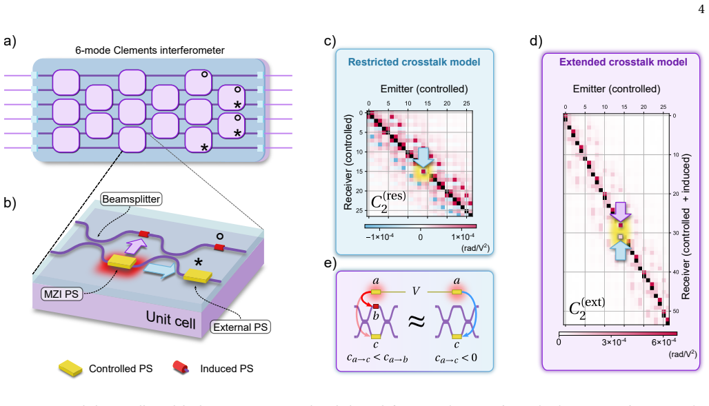
The load-bearing machinery is the extended crosstalk matrix $C_2^{(\mathrm{ext})}$, a rectangular $n_{\mathrm{PS}}\times n_{\mathrm{CPS}}$ matrix that includes one row per controlled or induced phase shifter and one column per controlled shifter. The argument moves by invariant phase transformations, modifications of phase-shifter settings that leave all measurable optical outputs unchanged, derived from two local rewriting rules, $\varphi$-cross and $\varphi$-merge, combined into a $\varphi$-remove rule that shifts an induced phase through the circuit and merges it into controlled shifters. Applying these transformations as row operations reduces the rectangular matrix to a square invertible one whenever possible. The decisive criterion is Theorem 2: the pruned graph must be acyclic, and the number of edges that must be cut to make it acyclic equals the circuit rank, i.e. the minimum number of additional controlled phase shifters needed for full mitigation.
What would settle it
Take a small interferometer whose pruned graph contains a cycle, such as a two-mode Mach-Zehnder interferometer followed by two beamsplitters, which the paper says is universal but not crosstalk-robust. If, after applying the proposed matrix-reduction protocol, its rectangular crosstalk matrix could be reduced to a square invertible matrix by linear invariant phase transformations, the acyclicity criterion would be refuted.
Extended reading notes
Core claim
The central claim is that every waveguide segment of a photonic circuit acquires a phase under actuation of any nearby heater, so a complete crosstalk model must assign an induced phase shifter to each bare segment. The resulting phase-voltage relation is Eq. (3): $\vec{\varphi}^{(\mathrm{ext})}=C_2^{(\mathrm{ext})}\cdot \vec{V}^{\odot2}+\vec{c}_0^{(\mathrm{ext})}$, with $C_2^{(\mathrm{ext})}$ an $n_{\mathrm{PS}}\times n_{\mathrm{CPS}}$ rectangular matrix rather than a square restricted matrix. Because the system is underdetermined, mitigation requires deleting induced rows through invariant phase transformations; the paper proves (Theorem 2) that all induced shifters can be removed exactly when the interferometer's pruned graph, the graph of beamsplitter nodes and waveguide edges with controlled-PS edges deleted, is acyclic. Consequently, Reck, Clements, and Bell-Walmsley universal interferometers are crosstalk-robust, whereas several specialized interferometers with cyclic pruned graphs cannot fully cancel crosstalk despite being otherwise functional. The authors validate the extended model on a 12-mode Clements device, showing it recovers short-range physical crosstalk and supports full control accuracy after matrix reduction.
Load-bearing premise
The continuous thermal phase profile on a bare waveguide is faithfully represented by a finite set of discrete lumped phase shifters at fixed positions; if that lumping is inaccurate, the rectangular extended crosstalk matrix and the graphical criterion describe a model that may not match the physical device.
Editorial extensions
If this is right
- Universal interferometers (Reck, Clements, Bell-Walmsley) can in principle reach full control accuracy after crosstalk matrix reduction, even though their bare waveguides suffer induced phase shifts.
- Interferometers whose pruned graph contains cycles, including some specialized two-mode universal designs, cannot have their crosstalk fully cancelled by linear invariant phase transformations, no matter how the voltages are chosen.
- Adding one controlled phase shifter for each cycle of the pruned graph, the graph's circuit rank, makes a non-crosstalk-robust interferometer fully crosstalk-robust.
- A machine-learning model equipped with the extended rectangular crosstalk matrix converges on meshes where the restricted square-matrix model fails to converge, with no increase in the required number of training samples.
- On the 12-mode Clements device, the extended model matches the restricted model's control fidelity while giving a physically local, interpretable crosstalk map that can benchmark fabrication improvements.
Reading between the lines
- Editorial inference: the pruned-graph criterion gives a concrete pre-fabrication design rule: specialized interferometers can be made resilient by adding at least one controlled phase shifter per cycle, rather than equipping every waveguide with a heater.
- Editorial inference: if strain- or electro-optic crosstalk also induces phases on bare waveguide sections, the same rectangular-matrix reduction and acyclicity criterion should apply, and could be tested by comparing measured output distributions with and without induced shifters in the model.
- Editorial inference: the observed equivalence of test error for restricted and extended models on Clements meshes suggests that the practical value of the extended model will show up most strongly on non-universal, cycle-containing meshes where the restricted model cannot converge.
Editorial analysis
A structured set of objections, weighed in public.
Referee Report
Summary. The manuscript introduces the notion of an induced phase shifter to describe thermal crosstalk-induced phases on waveguide sections that lack controlled phase shifters, promotes the restricted square crosstalk matrix to a rectangular extended matrix C^(ext)_2 (Eq. 3), and develops a machine-learning characterization procedure for this matrix. It then proposes crosstalk mitigation by reducing the rectangular matrix to a square one through invariant phase transformations derived from local circuit rewriting rules, and establishes a graphical criterion (Theorem 2) stating that a PIC is crosstalk-robust if and only if its pruned graph is acyclic. The authors validate the thermal origin of induced PSs with FEM simulations, benchmark the ML characterization on simulated Clements and MZI meshes, apply the mitigation protocol on a physical 12-mode Clements interferometer, and report comparable fidelity for restricted and extended models while arguing that the extended matrix is physically more faithful.
Significance. If the central claims hold, this is a practically valuable contribution to programmable photonic circuit control. The induced-PS concept and the rectangular extended crosstalk matrix provide a systematic way to think about crosstalk beyond controlled phase shifters, and the acyclicity criterion gives a simple design rule for crosstalk-robust interferometer meshes. The paper earns credit for combining thermal FEM simulation, ML-based characterization on simulated and physical devices, an algorithm for matrix reduction, and an experimental demonstration on a commercial 12-mode Clements interferometer. The reduction step and the graphical criterion are nontrivial and are backed by proofs in Appendices C-E, although the 'only if' direction of Theorem 2 is restricted to the paper's linear φ-remove rule set. The hardware experiment is an independent benchmark that prevents the simulation results from being purely circular.
major comments (3)
- [Section IV B and Appendix E 1 (Theorem 2)] The paper's headline conclusion overreaches the proof. Section IV B explicitly restricts the mitigation framework to linear relationships obtained via φ-remove, noting that nonlinear identities such as axiom E2 in [32] could remove additional induced PSs but are set aside. Theorem 2, as proven in Appendix E 1, therefore establishes equivalence between acyclicity and reducibility only within that restricted linear rule set. The Conclusion's statement that 'some PIC interferometer designs are fundamentally flawed, preventing effective crosstalk cancellation' is a no-go claim over all possible invariant phase transformations, and that stronger statement is not proven. Please either prove the no-go result for the full class of invariant phase transformations or rephrase the conclusion and Theorem 2 as a statement about the linear φ-remove framework, with the nonlinear possibility explicitly flagged as an open question.
- [Section II, Fig. 2b, and Eq. (3)] A load-bearing modeling assumption is that a continuous thermal phase profile on a bare waveguide can be represented by a finite set of discrete, lumped induced phase shifters at fixed positions, as asserted by 'all the circuit waveguide portions feature either an initially present controlled PS, or an added induced PS'. The paper does not quantify the approximation error of this lumping, and Fig. 1c shows a distributed phase profile while the subsequent mathematical treatment uses point PSs. If the lumped representation is not faithful, the extended crosstalk matrix and the reduction criterion apply to a model that may not match the physical device. Please provide a quantitative comparison between the distributed thermal phase profile and its lumped representation, or state this as an explicit idealization with supporting evidence.
- [Section III and Methods ('Simulation benchmark of the training process')] The simulated benchmarks in Fig. 3 use a device whose crosstalk is generated by the same functional form f(d) (Eq. 10) that the extended MLM is designed to fit, so these simulations demonstrate self-consistency of the model class rather than predictive power. This does not invalidate the central claim because the hardware experiment in Section V is an independent test, but the text should clearly distinguish the self-consistency nature of the simulation benchmarks from the experimental validation, especially when claiming in Section III that the extended MLM 'converges on more interferometer meshes'.
minor comments (5)
- [Section III b] There is a typo: 'the the inability of the restricted model to converge' should read 'the inability of the restricted model to converge'.
- [Introduction] The word 'litterature' in the Introduction should be 'literature'.
- [Fig. 4d caption] The caption contains '55 of the initial 186 induced PS cannot not be removed from the MZI mesh', which should be 'cannot be removed'.
- [Appendix G] The Fig. 12 caption says 'The purple (resp. purple) curve' where the second color should presumably be a different color to distinguish restricted and extended models.
- [Methods ('Reduced matrix invertibility')] The statement that the reduced matrix is 'typically invertible' is informal; please state more explicitly the conditions under which the reduction framework guarantees an invertible square matrix, since the mitigation protocol depends on this property.
Circularity Check
No significant circularity: the extended model is motivated by independent thermal simulations and validated on hardware; the graph criterion is a stated-rule consequence, with only a proof-scope caveat about nonlinear phase identities.
full rationale
The paper's central derivation is not circular. The induced-PS concept is introduced from finite-element thermal simulations (Section II, Fig. 1) and the extended MLM is validated against a commercial 12-mode Clements interferometer (Section V), an external benchmark independent of the fitted matrices. Theorems 1 and 2 are mathematical consequences of the explicitly stated invariant-transformation definitions: Theorem 1 is a row-deletion lemma proved from Lemma C1, and Theorem 2 is a graph-theoretic characterization of the φ-remove reduction process proved in Appendix E. The simulation benchmarks of Fig. 3 generate data from the extended model itself; this makes the extended MLM's convergence advantage on the MZI mesh a consistency check rather than independent physical evidence, but the paper does not use those simulations as the sole support for physical fidelity, and it explicitly verifies the mechanism by removing induced PSs and observing restricted-model convergence. Self-citations [20,31,32] supply the ML protocol and rewriting rules, but those rules are also attributed to independent prior work [29,30] and are elementary circuit identities; no load-bearing claim reduces to a self-citation. The only proof-scope caveat is that Theorem 2's 'only if' applies to linear φ-remove transformations; Section IV B explicitly acknowledges that nonlinear phase identities (e.g., axiom E2 in [32]) could remove additional induced PSs. That caveat limits the strength of the 'fundamentally flawed' physical conclusion, but it is an overclaim/correctness-risk, not a circular derivation, because the theorem is stated relative to that rule set rather than smuggling the conclusion into the premises.
Assumptions & free parameters
free parameters (2)
- Simulation crosstalk function f(d) =
0.5/d^2 for d != 0; 0.02 for d = 0; diagonal coefficient 0.034
- ML optimizer hyperparameters =
Learning rates 10^-5, 5x10^-6, 1x10^-6 for varying mode counts; Adam beta (0.99, 0.9999)
assumptions (5)
- domain assumption The phase-voltage relation is dominated by the order-2 term, so only C_2 and passive phases are needed (Eq. 3, Appendix B).
- ad hoc to paper Every waveguide section features either a controlled PS or an induced PS at a discrete position (Section II, Fig 2b); a continuous thermal phase profile is representable as such lumped phase shifters.
- domain assumption The circuit rewriting rules phi-cross and phi-merge (and derived phi-remove) are valid for the PICs considered, i.e., the devices are described by ideal lossless linear-optical unitaries for the purpose of finding invariant phase transformations (Section IV B, Fig 5a).
- domain assumption Input and output ports are phase-invariant for the mitigation analysis (Section IV A, Fig 6).
- ad hoc to paper The learned extended crosstalk matrix is a faithful representative among the gauge-equivalent matrices that fit the data (Section V, Fig 7).
invented entities (1)
-
Induced phase shifter (induced PS)
independent evidence
Cite this review
Pith. "Pith review of Resource-efficient crosstalk mitigation for the high-fidelity operation of photonic integrated circuits with induced phase shifters." pith.science (2026). https://pith.science/paper/YQPZK72U
@misc{pith2026250605988,
  author       = {Pith},
  title        = {Pith review of: Resource-efficient crosstalk mitigation for the high-fidelity operation of photonic integrated circuits with induced phase shifters},
  year         = {2026},
  howpublished = {\url{https://pith.science/paper/YQPZK72U}},
  note         = {Machine review of arXiv:2506.05988}
}
read the original abstract
Photonic integrated circuits (PICs) are key platforms for the compact and stable manipulation of classical and quantum light. Imperfections arising from fabrication constraints, tolerances, and operation wavelength limit the accuracy of intended operations on light and impede the practical utility of current PICs. In particular, crosstalk between reconfigurable phase shifters is challenging to characterize due to the large number of parameters to estimate and the difficulty in isolating individual parameters. Previous studies have attempted to model crosstalk solely as an interaction between controlled phase shifters, overlooking the broader scope of this issue. We introduce the concept of induced phase shifter, arising from crosstalk on bare waveguide sections as predicted by simulations, resulting in an exhaustive description and systematic analysis of crosstalk. We characterize induced phase shifters in physical devices using a machine learning-based method and propose a mitigation framework. This framework further allows to establish a criterion certifying that a given interferometer has a sufficient number of degrees of freedom adequately laid out to fully mitigate crosstalk. Our approach is experimentally validated on a 12-mode Clements interferometer. We demonstrate the efficacy of our extended crosstalk model to accurately recover physical crosstalk properties of the PIC and cancel induced phase shifters following our mitigation framework.
Figures


Figures from the paper (9 more)


Reference graph
Works this paper leans on
-
[32]
Clements, W . R., Humphreys, P . C., Metcalf, B. J., Kolthammer, W . S. & Walmsley, I. A. Optimal design for universal multiport interferometers. Optica 3, 1460–1465 (2016)
work page 2016
-
[1]
Apply the transformation Ri − →Ri + αi Rk for i ̸= k (6) to the crosstalk matrix C (ext) 2 of the PIC, where R i des- ignates the i-th row of C(ext) 2
-
[2]
Wang, J., Sciarrino, F ., Laing, A. & Thompson, M. G. Inte- grated photonic quantum technologies. Nature Photonics 14, 273–284 (2020)
work page 2020
-
[3]
+" sign) and subtracting φ13 from the phase of PSs indexed 5, 9 and 14 (PSs with a
Remove the k-th PS from the circuit. In Theorem 1, invariant phase transformations are mod- ifications of the implemented PIC phase shifts that leave the measurable outcomes invariant. Invariant phase trans- formations are a property both of the PIC and the optical setup. For instance, if the PIC is followed by light intensity detectors, then applying add...
work page 2000
-
[4]
can be applied to remove the induced PS from the cir- cuit and delete its associated row in the crosstalk matrix. If an induced PS is not adjacent to three controlled PSs, then the φ-remove rule must be repeatedly applied until all cre- ated phase shifts have been merged with controlled PSs or moved out of the circuit (see Fig. 5c). App. D introduces an e...
-
[5]
Bogaerts, W . et al. Programmable photonic circuits. Nature 586, 207–216 (2020)
work page 2020
-
[6]
Zhong, H.-S. et al. Quantum computational advantage using photons. Science 370, 1460–1463 (2020)
2020
-
[7]
Marpaung, D., Yao, J. & Capmany, J. Integrated microwave photonics. Nature Photonics 13, 80–90 (2019)
work page 2019
Show all 51 references
-
[8]
Heck, M. J. R. Highly integrated optical phased arrays: pho- tonic integrated circuits for optical beam shaping and beam steering. Nanophotonics 6, 93–107 (2017). 14
2017
-
[9]
M., Cheung, K
Luan, E., Shoman, H., Ratner, D. M., Cheung, K. C. & Chros- towski, L. Silicon photonic biosensors using label-free de- tection. Sensors 18 (2018). URL https://www.mdpi.com/ 1424-8220/18/10/3519
2018
-
[10]
Polino, E. et al. Experimental multiphase estimation on a chip. Optica 6, 288–295 (2019)
2019
-
[11]
Maring, N. et al. A versatile single-photon-based quantum computing platform. Nature Photonics 1–7 (2024)
2024
-
[12]
Luo, W . et al. Recent progress in quantum photonic chips for quantum communication and internet. Light: Science and Applications 12, 175 (2023)
2023
-
[13]
Fyrillas, A. et al. Certified randomness in tight space. PRX Quantum 5, 020348 (2024)
2024
-
[14]
& Chakrabarty, K
Banerjee, S., Nikdast, M. & Chakrabarty, K. Characterizing co- herent integrated photonic neural networks under imperfec- tions. Journal of Lightwave Technology 41, 1464–1479 (2023). ArXiv:2207.10835 [cs, eess]
2023 arXiv
-
[15]
Harris, N. C. et al. Efficient, compact and low loss thermo- optic phase shifter in silicon. Optics Express 22, 10487–10493 (2014)
2014
-
[16]
Dong, M. et al. High-speed programmable photonic circuits in a cryogenically compatible, visible–near-infrared 200 mm cmos architecture. Nature Photonics 16, 59–65 (2022)
2022
-
[17]
Li, M. et al. Lithium niobate photonic-crystal electro-optic modulator. Nature Communications 11, 4123 (2020)
2020
-
[18]
Pont, M. et al. High-fidelity four-photon ghz states on chip. npj Quantum Information 10, 1–7 (2024)
2024
-
[19]
Bandyopadhyay, S. et al. Single chip photonic deep neu- ral network with accelerated training (2022). URL http:// arxiv.org/abs/2208.01623. ArXiv:2208.01623 [physics]
2022 arXiv
-
[20]
& Morichetti, F
Milanizadeh, M., Aguiar, D., Melloni, A. & Morichetti, F . Can- celing thermal cross-talk effects in photonic integrated cir- cuits. Journal of Lightwave Technology 37, 1325–1332 (2019)
2019
-
[21]
Milanizadeh, M. et al. Control and calibration recipes for pho- tonic integrated circuits. IEEE Journal of Selected Topics in Quantum Electronics 26, 1–10 (2020)
2020
-
[22]
Zhu, Y. et al. Countering variations and thermal effects for ac- curate optical neural networks. In Proceedings of the 39th In- ternational Conference on Computer-Aided Design, 1–7 (ACM, Virtual Event USA, 2020). URL https://dl.acm.org/doi/ 10.1145/3400302.3415682
2020
-
[23]
Pentangelo, C. et al. High-fidelity and polarization- insensitive universal photonic processors fabricated by femtosecond laser writing. Nanophotonics (2024). URL https://www.degruyter.com/document/doi/10.1515/ nanoph-2023-0636/html
2024
-
[24]
& Belabas, N
Fyrillas, A., Faure, O., Maring, N., Senellart, J. & Belabas, N. Scalable machine learning-assisted clear-box characteri- zation for optimally controlled photonic circuits. Optica 11, 427–436 (2024)
2024
-
[25]
Rodari, G. et al. Semi-device independent characterization of multiphoton indistinguishability (2024). URL http:// arxiv.org/abs/2404.18636. ArXiv:2404.18636 [quant-ph]
2024 arXiv
-
[26]
Calibration of multiparameter sensors via ma- chine learning at the single-photon level
Cimini, V .et al. Calibration of multiparameter sensors via ma- chine learning at the single-photon level. Physical Review Ap- plied 15, 044003 (2021)
2021
-
[27]
& Domínguez, C
Alemany, R., Muñoz, P ., Pastor, D. & Domínguez, C. Thermo- optic phase tuners analysis and design for process modules on a silicon nitride platform. Photonics 8 (2021). URL https: //www.mdpi.com/2304-6732/8/11/496
2021
-
[28]
Ceccarelli, F . et al. Low power reconfigurability and re- duced crosstalk in integrated photonic circuits fabricated by femtosecond laser micromachining. Laser & Photonics Reviews 14, 2000024 (2020). URL https://onlinelibrary. wiley.com/doi/abs/10.1002/lpor.202000024. https:/...
2020 doi
-
[29]
Simulation benchmark of the training process
universal interferometers are crosstalk-robust. On the contrary, specialized interferometers such as [33–36] are not crosstalk-robust for instance. Remarkably, we can highlight that universal schemes are not necessarily crosstalk-robust. Indeed, an MZI followed by two beamspli...
2000
-
[30]
Reck, M., Zeilinger, A., Bernstein, H. J. & Bertani, P . Experi- mental realization of any discrete unitary operator. Physical Review Letters 73, 58–61 (1994)
1994
-
[31]
Youssry, A. et al. Experimental graybox quantum system iden- tification and control. npj Quantum Information 10, 1–9 (2024)
2024
-
[33]
Bell, B. A. & Walmsley, I. A. Further compactifying linear opti- cal unitaries. APL Photonics 6, 070804 (2021)
2021
-
[34]
Pont, M. et al. Quantifying n-photon indistinguishability with a cyclic integrated interferometer. Physical Review X 12, 031033 (2022)
2022
-
[35]
& Valiron, B
Clément, A., Heurtel, N., Mansfield, S., Perdrix, S. & Valiron, B. Lov-calculus: A graphical language for linear optical quantum circuits (2022). URL http://arxiv.org/abs/2204.11787. ArXiv:2204.11787 [quant-ph]
2022 arXiv
-
[36]
A complete graphical language for linear op- tical circuits with finite-photon-number sources and de- tectors (2024)
Heurtel, N. A complete graphical language for linear op- tical circuits with finite-photon-number sources and de- tectors (2024). URL http://arxiv.org/abs/2402.17693. ArXiv:2402.17693 [quant-ph]
2024 arXiv
-
[37]
Li, H. W . et al. Calibration and high fidelity measurement of a quantum photonic chip. New Journal of Physics 15, 063017 (2013). ArXiv:1306.1719 [quant-ph]
2013 arXiv
-
[38]
Metcalf, B. J. et al. Quantum teleportation on a photonic chip. Nature Photonics 8, 770–774 (2014)
2014
-
[39]
Shadbolt, P . J. et al. Generating, manipulating and measur- ing entanglement and mixture with a reconfigurable photonic circuit. Nature Photonics 6, 45–49 (2012)
2012
-
[40]
Peruzzo, A. et al. A variational eigenvalue solver on a photonic quantum processor. Nature Communications 5, 4213 (2014)
2014
-
[41]
The Theory of Graphs
Berge, C. The Theory of Graphs. Dover books on mathematics (Dover Publications, 2001)
2001
-
[42]
Taballione, C. et al. A universal fully reconfigurable 12-mode quantum photonic processor. Materials for Quantum Tech- nology 1, 035002 (2021)
2021
-
[43]
Palik, E. D. Handbook of optical constants of solids, vol. 3 (Aca- demic press, 1998)
1998
-
[44]
Philipp, H. R. Optical properties of silicon nitride. Journal of the Electrochemical Society 120, 295 (1973)
1973
-
[45]
Graphs and Hypergraphs , vol
Berge, C. Graphs and Hypergraphs , vol. 6 of North-Holland Mathematical Library (North-Holland Publishing Company, Amsterdam, 1973), revised edn. 15 Appendix A: PARAMETERS AND RESULTS OF THE THERMAL SIMULATIONS A detail of the phase shifter (PS) cross section considered for th...
1973
-
[46]
Statement Consider a PIC with PSs labeled 1, ...,nPS (including controlled and induced phase shifters) and extended crosstalk matrix C of size nPS × nCPS
Lemma for C 2 a. Statement Consider a PIC with PSs labeled 1, ...,nPS (including controlled and induced phase shifters) and extended crosstalk matrix C of size nPS × nCPS. Suppose that there exists an invariant phase transformation (see Section IV A) of the form ∀i ∈ 1,nPS, ...
-
[47]
Statement Consider a PIC with PSs labeled 1, ...,nPS (including controlled and induced phase shifters) and extended crosstalk matrix C of size nPS × nCPS
Proof of Theorem 1 (Crosstalk matrix row deletion) a. Statement Consider a PIC with PSs labeled 1, ...,nPS (including controlled and induced phase shifters) and extended crosstalk matrix C of size nPS × nCPS. Suppose that PS k is an induced PS and that there exists an invarian...
-
[48]
We say that an in- duced PS is removable when its implemented phase shift can be moved out of the circuit as exemplified in Fig
Algorithm We introduce a phase simplification algorithm to efficiently find the removable induced phase shifters (PSs) in a given photonic integrated circuit (PIC) and the associated invariant phase transformations (see Section IV B). We say that an in- duced PS is removable w...
-
[49]
We consider first the general case
Algorithmic complexity We now discuss the complexity of the phase simplification algorithm. We consider first the general case. The total number of induced PSs to label is less thannPS, as we never reconsider already labeled induced PSs. Establishing a phase relationship betwe...
-
[50]
Statement A PIC is crosstalk-robust if and only if its associated pruned graph is acyclic
Proof of Theorem 2 (Crosstalk-robustness criterion) a. Statement A PIC is crosstalk-robust if and only if its associated pruned graph is acyclic. Output nodeInput node a) c)b) Input ports Output ports FIG. 10. Graph representation of Fig. 6b. Red edges indicate phase invariant...
-
[51]
Non crosstalk-robust interferometers feature induced PSs that cannot be removed from the circuit
Proof of maximal reduction for non-crosstalk-robust interferometers: circuit rank of the pruned graphs When the interferometer is not crosstalk-robust, then by definition its crosstalk matrix cannot be fully reduced to a square matrix (see Section IV C). Non crosstalk-robust i...
Reviewed August 7, 2026 · model on record in the stance chip above.
Discussion (0). Sign in to comment.