REVIEW 4 major objections 6 minor 16 references
Experimental Performances of mmWave RIS-assisted 5G-Advanced Wireless Deployments in Urban Environments
T0 review · 4 major / 6 minor · reviewed 2026-08-07 · deepseek-v4-flash
Pith's one-line read Field trials show mmWave RIS delivering ~20 dB gains and 4x throughput in urban 5G-Advanced deployments.
desk verdict Genuinely new commercial-scale mmWave RIS field trial, but the headline 20 dB/4x gains are confounded by simultaneous AAU beam changes and lack of repetition. read the letter →
The pith
A machine-rendered reading of the paper's core claim, the machinery that carries it, and where it could break.
The reading
What carries the argument
The load-bearing mechanism is the RIS itself: a 132×132 array of two-state phase-shifter elements (17,424 elements in total) that forms codebook-defined beams in the mmWave band. The network treats the RIS as an anchor: the active antenna unit (AAU) broadcasts SSBs through RIS codebooks with beamwidths of 2°–6°, selects the best beam for the moving CPE, and performs beam tracking as the CPE's position changes. This lets a blockage-prone mmWave link be replaced by a reflected path that is strong enough to register the CPE and carry traffic, which is what produces the measured jumps in RSRP/SINR and throughput.
What would settle it
Repeat the Kartal drive test with the RIS codebook set to a fixed, non-deflecting state (or with the RIS shielded by absorber) while keeping everything else identical: if RSRP and SINR still show about 20 dB improvements over the RIS-off run, the gains are not caused by RIS reflection. Alternatively, re-run the same trajectory three times with RIS on and three times with RIS off and show that between-run variance is small compared with the claimed 20 dB gap.
Extended reading notes
Core claim
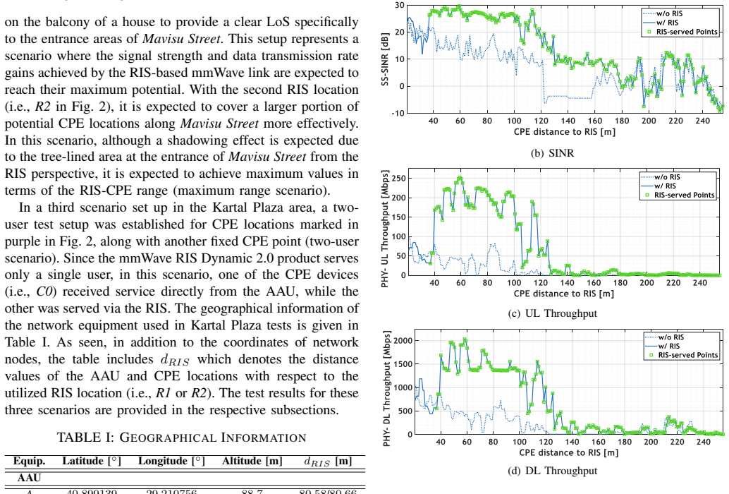
The central discovery is that a dynamic RIS integrated into a live mmWave 5G-Advanced network produces large, consistent improvements in RF power and throughput along a street-level trajectory. In the best-case geometry, with the RIS on a balcony overlooking the street, activation yielded typical gains of about 20 dB in RSRP and SINR and roughly 4x uplink and downlink data rates for customer premises equipment (CPE) locations up to 110 m from the RIS; beyond that, gains taper but persist to 180 m. Repositioning the RIS to a more dominant location extended the range of intense gains to about 210 m, with the network performing beam tracking over RIS-generated synchronization signal block (SSB) beams (index range 3–15) as the CPE moved. In the multi-user check, a second CPE served directly by the base station's active antenna unit (AAU) was unaffected when the RIS was switched on, while the RIS-served CPE improved markedly, indicating the RIS offloads traffic rather than stealing resources. In the VR test, RIS activation moved end-to-end latency from above 40 ms into the 11–22 ms window, meeting the application's 35 ms requirement.
Load-bearing premise
The reported gains assume that the RIS-off and RIS-on drive-test records are directly comparable, meaning the CPE followed the same path, nothing else in the network changed, and the roughly 20 dB and 4x differences are caused by the RIS rather than by scheduling, beam changes, or environmental drift.
Editorial extensions
If this is right
- If these field results generalize, operators can extend mmWave coverage into street canyons and shadow zones without adding base stations, by placing a steerable RIS at a location with line of sight to both the base station and the target area.
- The 20 dB power gain and 4x throughput imply that RIS assistance can convert mmWave from a fragile, short-range technology into a more dependable urban broadband access option, at least for single-user fixed wireless access.
- The VR result shows a concrete latency budget: with WiFi6 contributing 8–20 ms and server processing about 5 ms, the RIS-assisted mmWave link must keep round-trip time under about 10 ms; the deployment achieves this, so RIS can support latency-critical immersive applications today.
- The multi-user test suggests a division of labor: the RIS serves one challenging user while the base station serves others directly, a practical near-term deployment mode before true multi-user RIS beamforming matures.
Reading between the lines
- A natural next test the paper does not report is whether the same gains persist for CPE locations outside line of sight of the RIS, since all strong results here are for LoS or near-LoS geometries.
- The reported 4x throughput suggests RIS-assisted links could serve as a low-cost alternative to deploying additional small cells in urban mmWave rollouts, a cost comparison the paper leaves implicit.
- The beam-tracking behavior over SSB indices 3–15 implies the RIS codebook follows the CPE trajectory; an immediate extension would be to measure switching latency and handover failure rate, which are not reported.
- If the 20 dB figure is reproducible in other cities, RIS becomes a candidate for closing the 'last 100 meters' of mmWave coverage, but the single-user limitation noted by the authors means dense urban deployments still await a multi-user product.
Editorial analysis
A structured set of objections, weighed in public.
Referee Report
Summary. This paper reports field measurements of a ZTE Dynamic 2.0 reconfigurable intelligent surface (a 132x132 unit-cell mmWave reflector) integrated into Turkcell's n258-band 5G-Advanced private network. Three outdoor scenarios are presented at a Kartal test site: (i) a "maximum gains" drive test in which activating the RIS is reported to improve RSRP and SINR by about 20 dB and UL/DL throughput by about 4-fold over a served corridor up to about 110 m from the RIS, with reduced effect out to about 180 m; (ii) a "maximum range" configuration in which the gains extend to about 210 m, accompanied by serving SSB beam indices that shift from 1-2 (RIS off) to the interval [3,15] (RIS on); and (iii) a two-user test showing that a directly served CPE is unaffected by the RIS while a second CPE is enhanced. At a second site (Kucukyali), the RIS supports a VR ping-pong application through a fixed wireless access link, with reported end-to-end latency in [11,22] ms with RIS on versus greater than 40 ms with RIS off. The authors conclude that product-level RIS can improve mmWave coverage, multi-user efficiency, and latency-critical applications, and they list integration, multi-user, and interference challenges for future work.
Significance. If the reported gains hold under controlled conditions, this would be a valuable addition to the sparse set of product-level RIS field trials in commercial-style mmWave networks: it integrates a large-aperture RIS into a live 5G-Advanced setup, performs continuous beam tracking over a mobile trajectory, addresses multi-user offloading, and includes a latency-critical VR use case. The quantitative claims (about 20 dB RSRP/SINR, about 4x throughput, about 210 m range extension, and 35 ms VR latency compliance) are specific and falsifiable, and Section IV candidly lists the main deployment obstacles (OSS integration, single-user RIS limitation, interference), which strengthens the paper's credibility. The main weaknesses are experimental control and statistical support: there are no repeated trials, no error bars, no detailed matching criterion, and the comparison bundles RIS activation together with AAU SSB beam reconfiguration. The paper's value would be substantially higher if the authors separated the RIS contribution from the AAU codebook changes and provided per-waypoint paired statistics.
major comments (4)
- [Section III-A.2 and Fig. 4(b)] The comparability of the RIS-off and RIS-on conditions is not established, and the paper's own description shows that the two conditions differ in more than RIS activation. In the RIS-on case the CPE registers on SSB beam indices in [3,15], whereas in the RIS-off baseline it registers on SSB beams 1 and 2 (Section III-A.2, Fig. 4(b)). An SSB beam index identifies a beamformed transmit configuration of the AAU, so the AAU transmit beam weights and initial-access procedure are not the same in the two states. Combined with the statement in Section II-B that the SSB beams "have been optimized to serve the CPE device" via the configuration-loading codebooks of the RIS, the reported about 20 dB RSRP/SINR advantages and the about 4-fold throughput gains in Sections III-A.1 and III-A.2 should be read as the joint effect of RIS activation and AAU codebook reconfiguration, not as the RIS alone. The authors should either provide a control run in which the AAU SSB codebook is identical in both RIS states, or explicitly redefine the claimed quantity as the RIS-assisted (joint RIS plus AAU optimization) gain and, if possible, quantify how much of the observed gap comes from the beam-index change alone.
- [Section II-B] The matching procedure for the RIS-off and RIS-on KPI records is not described. The text states only that "the independently collected KPI records for both RIS-off and RIS-on cases along the specified trajectory have been used to match and compare" (Section II-B); no criterion is given for aligning waypoints across separate drives, no revisit or dwell rule, and no inter-run variance is reported. Outdoor mmWave shadowing from vehicles, pedestrians, and trees can fluctuate by tens of decibels between runs at the same location, so the central effect sizes of about 20 dB and 4x carry no stated uncertainty and are not falsifiable as reported. Repeated, interleaved A/B measurements with per-waypoint paired differences (or at least error bars per distance bin) are needed to support the claimed magnitudes.
- [Table III] The VR latency evidence in Table III consists of a single RIS-off value (>40 ms) and a single RIS-on interval ([11,22] ms), with no sample size, measurement duration, latency distribution, or repetition. Since the paper itself states that the WiFi6 leg contributes an RTT in [8,20] ms and the VR server requires about 5 ms, the reported [11,22] ms interval lies within the range that could be produced by the WiFi/server components alone, and the causal link between RIS activation and latency compliance is underdetermined by a single un-replicated observation. The authors should report the mmWave-leg RTT separately, per-trial latency percentiles, and at least a small number of on/off repetitions so that the RIS contribution can be isolated.
- [Section III-A.1] The headline quantitative claims ("enhancements ... solid for the CPE locations up to 110 meters from RIS", RSRP/SINR gains "typically about 20 dB", UL/DL data rates "enhanced by 4-folds") are stated without a defined aggregation rule. The text reports no per-waypoint paired differences, no distance-bin medians, and no uncertainty intervals; the claims rest on visual inspection of Fig. 3. Please specify exactly how the 20 dB and 4x figures were computed (for example, median over which waypoints and over which distance range) so that the central numbers are verifiable.
minor comments (6)
- [Section I] The sentence "Despite providing solid test trials, [13] and [14] lack to put analyze a commercial-like RIS product..." is ungrammatical and should be rewritten.
- [Abstract and Section I] Several frequency values lack spacing ("2.6GHz,4.9GHz, and26 GHz") and similar formatting issues appear elsewhere (for example, "2 –6 ◦" in Section II-B); the manuscript should be proofread for consistent typography.
- [Section IV heading] The heading contains a typo, "communicaiton", which should read "communication".
- [Table III] The E2E latency row mixes a point value (">40") with an interval ("[11,22]"); please clarify whether the interval is the min-max range over the session, an inter-percentile range, or a confidence interval, and state the number of measurements.
- [Acknowledgment] The acknowledgment discloses that ZTE shared the KPI results from the outdoor tests; this data-provenance statement is important and should also appear in Section II-B so that the reporting basis is explicit in the methodology.
- [Reference [16]] The WiFi6 latency claim ([8,20] ms) is supported by a vendor white paper; consider citing an independent standard or measurement source for that range.
Circularity Check
No circularity: the reported gains are direct field measurements, not derived from fitted parameters or self-citation chains; the vendor-data and AAU-beam-configuration concerns are validity threats, not circularity.
full rationale
This is an experimental measurement study with no model-fitting, no equations, and no prediction derived from an input. The claimed ~20 dB RSRP/SINR and ~4x throughput gains are observed differences between RIS-off and RIS-on KPI records along a trajectory (Section III-A), and the VR latency result is a single off/on measurement (Table III). None of the circularity patterns applies: no parameter is fit to a subset and then renamed a prediction; no uniqueness theorem is imported from the authors' prior work; no ansatz is smuggled via citation; and no known result is merely renamed. The self-citations (refs. [12], [13]) are background citations for prior RIS experiments and are not load-bearing for the present measurements. The acknowledgment that ZTE shared the KPI records is a provenance/independence issue, and the Section II-B statement that SSB beams were 'optimized' in the RIS-on case and that the RIS-off baseline used SSB beams 1–2 (Section III-A.2) reveals a potential confound (RIS activation is bundled with different AAU beam indices and separate drive runs), but this is a validity/causal-attribution limitation, not circularity: the numbers are still measured, not constructed. Accordingly no circular step is identified, and the score is 0.
Assumptions & free parameters
assumptions (4)
- domain assumption The ZTE Dynamic 2.0 RIS operates as specified, with a 132x132 array of two-state phase shifter elements, predefined codebook beams, and single-user service capability.
- domain assumption The RIS-off and RIS-on KPI records are directly comparable because the CPE followed the same trajectory and the only meaningful change was RIS activation.
- domain assumption The observed RSRP, SINR, and throughput differences are attributable to the RIS rather than to concurrent AAU beam changes, scheduler behavior, or environmental variation.
- domain assumption The VR E2E latency budget is correctly decomposed as WiFi6 RTT in [8,20] ms, VR server processing about 5 ms, and mmWave RTT below 10 ms.
Cite this review
Pith. "Pith review of Experimental Performances of mmWave RIS-assisted 5G-Advanced Wireless Deployments in Urban Environments." pith.science (2026). https://pith.science/paper/ZKF6LTVG
@misc{pith2026250606525,
  author       = {Pith},
  title        = {Pith review of: Experimental Performances of mmWave RIS-assisted 5G-Advanced Wireless Deployments in Urban Environments},
  year         = {2026},
  howpublished = {\url{https://pith.science/paper/ZKF6LTVG}},
  note         = {Machine review of arXiv:2506.06525}
}
read the original abstract
Reconfigurable intelligent surface (RIS) has emerged as a groundbreaking technology for 6G wireless communication networks, enabling cost-effective control over wireless propagation environment. By dynamically manipulating its codebook so as to deflect the direction of the reflected electromagnetic wave, RIS can achieve enhanced signal quality, extended coverage, and interference mitigation. This study presents experimental performance of ZTE Dynamic 2.0 RIS products through a series of real-world tests conducted on Turkcell's millimeter-wave (mmWave) testbed. The evaluation involves network coverage extension in urban areas, multi-user efficiency, and the integration of virtual reality technology to support immersive applications in next-generation 6G networks. Through a comprehensive measurement-based analysis, the performance of the RIS product is demonstrated, highlighting its potential to address critical challenges in mmWave communications and to enable advanced 6G use cases.
Figures


Figures from the paper (5 more)


Reference graph
Works this paper leans on
-
[1]
Design and evaluation of reconfigurable intelligent surfaces in real-world environment,
G. C. Trichopoulos, P. Theofanopoulos, B. Kashyap, A. Shekhawat, A. Modi, T. Osman, S. Kumar, A. Sengar, A. Chang, and A. Alkhateeb, “Design and evaluation of reconfigurable intelligent surfaces in real-world environment,” IEEE Open Journ. the Comm. Society, vol. 3, pp. 462–474, 2022
work page 2022
-
[2]
Path loss modeling for the RIS-assisted channel in a corridor scenario in mmwave bands,
Y . Li, J. Zhang, P. Tang, L. Tian, X. Zhao, H. Xu, and H. Gong, “Path loss modeling for the RIS-assisted channel in a corridor scenario in mmwave bands,” in IEEE Globecom Workshops, 2022, pp. 1478–1483
work page 2022
-
[3]
Impact of multiple RIS on channel characteristics: an experimental validation in ka band,
T. Mazloum, L. Santamaria, F. Munoz, A. Clemente, J.-B. Gros, Y . Nasser, M. Odit, G. Lerosey, and R. D’Errico, “Impact of multiple RIS on channel characteristics: an experimental validation in ka band,” in 2023 Joint European Conference on Networks and Communications & 6G Summit (EuCNC/6G Summit). IEEE, 2023, pp. 13–18
work page 2023
-
[4]
W. Tang, X. Chen, M. Z. Chen, J. Y . Dai, Y . Han, M. Di Renzo, S. Jin, Q. Cheng, and T. J. Cui, “Path loss modeling and measurements for reconfigurable intelligent surfaces in the millimeter-wave frequency band,” IEEE Trans. Commun., vol. 70, no. 9, pp. 6259–6276, 2022
work page 2022
-
[5]
Physical modeling of reconfigurable intelligent surface for channel modeling,
W. Miao and J. Dou, “Physical modeling of reconfigurable intelligent surface for channel modeling,” China Communications, vol. 22, no. 2, pp. 128–142, 2025
work page 2025
-
[6]
W. Tang, M. Z. Chen, X. Chen, J. Y . Dai, Y . Han, M. Di Renzo, Y . Zeng, S. Jin, Q. Cheng, and T. J. Cui, “Wireless communications with reconfigurable intelligent surface: Path loss modeling and experimental measurement,” IEEE Trans. Wire. Commun., vol. 20, no. 1, pp. 421–439, 2020
work page 2020
-
[7]
Reconfigurable intelligent surfaces: Channel characterization and modeling,
J. Huang, C.-X. Wang, Y . Sun, R. Feng, J. Huang, B. Guo, Z. Zhong, and T. J. Cui, “Reconfigurable intelligent surfaces: Channel characterization and modeling,” Proceedings of the IEEE, vol. 110, no. 9, pp. 1290–1311, 2022
work page 2022
-
[8]
On channel reciprocity in reconfigurable intelligent surface assisted wireless networks,
W. Tang, X. Chen, M. Z. Chen, J. Y . Dai, Y . Han, S. Jin, Q. Cheng, G. Y . Li, and T. J. Cui, “On channel reciprocity in reconfigurable intelligent surface assisted wireless networks,” IEEE Wireless Communications, vol. 28, no. 6, pp. 94–101, 2021
work page 2021
Show all 16 references
-
[9]
RIS- enabled mmwave channel sounding based on electronically reconfigurable transmitarrays,
A. Mudonhi, M. Lotti, A. Clemente, R. D’Errico, and C. Oestges, “RIS- enabled mmwave channel sounding based on electronically reconfigurable transmitarrays,” in 2021 15th European Conference on Antennas and Propagation (EuCAP). IEEE, 2021, pp. 1–5
2021
-
[10]
RIS-aided wireless communications: Prototyping, adaptive beamforming, and indoor/outdoor field trials,
X. Pei, H. Yin, L. Tan, L. Cao, Z. Li, K. Wang, K. Zhang, and E. Bjornson, “RIS-aided wireless communications: Prototyping, adaptive beamforming, and indoor/outdoor field trials,” IEEE Transactions on Communications, vol. PP, pp. 1–1, 09 2021
2021
-
[11]
Measurement-based small-scale channel model for sub-6 ghz ris-assisted communications,
J. Sang, J. Lan, M. Zhou, B. Gao, W. Tang, X. Li, M. Matthaiou, S. Jin, and M. Di Renzo, “Measurement-based small-scale channel model for sub-6 ghz ris-assisted communications,” IEEE Trans. Vehic. Techno., 2024
2024
-
[12]
Indoor Measurements of Reconfigurable Intelligent Surfaces in 5G Millimeter- Wave Networks,
C. Karakus ¸, H. Koc ¸ak, S. Kayraklik, S. Kes ¸ir, and Z. Yi ˘git, “Indoor Measurements of Reconfigurable Intelligent Surfaces in 5G Millimeter- Wave Networks,” in IEEE SIU, 2024, pp. 1–4
2024
-
[13]
Simulation and field trial results of reconfigurable intelligent surfaces in 5g networks,
R. Liu, J. Dou, P. Li, J. Wu, and Y . Cui, “Simulation and field trial results of reconfigurable intelligent surfaces in 5g networks,” IEEE Access, vol. 10, pp. 122 786–122 795, 2022
2022
-
[14]
Coverage enhancement by deploying RIS in 5g commercial mobile networks: Field trials,
J. Sang, Y . Yuan, W. Tang, Y . Li, X. Li, S. Jin, Q. Cheng, and T. J. Cui, “Coverage enhancement by deploying RIS in 5g commercial mobile networks: Field trials,” IEEE Wire. Commun., vol. 31, no. 1, pp. 172–180, 2022
2022
-
[15]
NodeEngine2.0 Whitepaper: Building a Simplified, Intelligent, and Open Industry Private Network,
“NodeEngine2.0 Whitepaper: Building a Simplified, Intelligent, and Open Industry Private Network,” ZTE Corporation, Tech. Rep., 2024
2024
-
[16]
Wi-Fi 6 Technology and Evolution White Paper,
“Wi-Fi 6 Technology and Evolution White Paper,” ZTE Corporation, Tech. Rep., 2020
2020
Reviewed August 7, 2026 · model on record in the stance chip above.
Discussion (0). Sign in to comment.