REVIEW 3 major objections 6 minor 16 references
Channel characterization in screen-to-camera based optical camera communication
T0 review · 3 major / 6 minor · reviewed 2026-08-06 · deepseek-v4-flash
Pith's one-line read The paper claims that a smartphone screen used as a transmitter behaves as a Lambertian emitter with order m=1, making the standard line-of-sight channel equation the right model for screen-to-camera links.
desk verdict Plausible m=1 Lambertian fit and a working 20-55 cm screen-to-camera link on a Pixel 6 Pro, but missing fit details and unclear novelty over the authors' own 2023 beam-profile paper make the headline number provisional. read the letter →
The pith
A machine-rendered reading of the paper's core claim, the machinery that carries it, and where it could break.
The reading
What carries the argument
The load-bearing object is the Lambertian radiant-intensity model R(φ)=((m+1)/(2π))cos^m(φ) and its LOS channel gain H_los(0) given in Eq. (1), with m the Lambertian order. The paper parameterizes the screen as an emitter with order m and determines m by fitting the normalized measured beam profile to this one-parameter curve, obtaining m=1. The same m appears in the half-angle relation m = −ln2/ln(cos φ_{1/2}), so one measured number links the beam shape to the channel equation used for link budget and success-rate analysis.
What would settle it
Measure the screen's radiant intensity with a goniophotometer in 1-degree steps across the full 180-degree hemisphere at constant drive level, and test the null hypothesis that R(φ) = (1/π)cos φ by computing residuals; if residuals exceed measurement noise near the edges of the field of view, the m=1 Lambertian model fails for the off-axis angles. A cheaper check: at fixed distance 20 cm, rotate the receiving phone from 0 to 80 degrees and compare the measured pixel intensity falloff to cos φ; a clear mismatch beyond the fitted range would falsify the claim.
Extended reading notes
Core claim
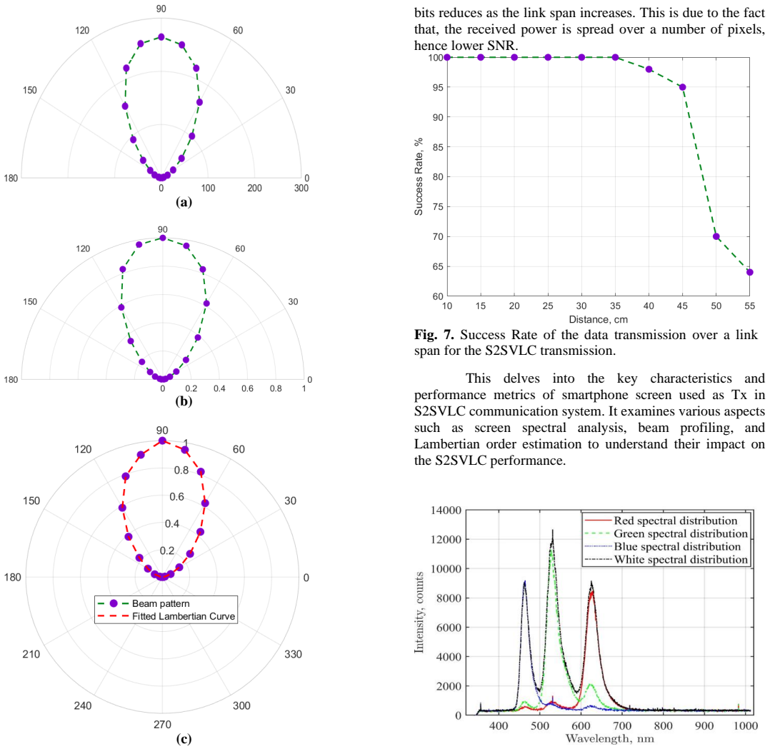
The central claim is that the emission pattern of a smartphone screen is Lambertian with order m=1, which makes the LOS DC gain H_los(0) = A_r (m+1)/(2π $d^{2}$) cos^m(φ) T_s(ψ) cos ψ with m=1 the correct channel description for a screen-to-camera link under no-tilt, no-rotation conditions. This is established by measuring the received power over 0–180 degrees in portrait and landscape configurations, normalizing the beam profile, and fitting the Lambertian curve R(φ)=(m+1)/(2π)cos^m(φ), which yields m=1. With this model the paper reports a working text link at 20 cm, success rate falling to 98% at 40 cm, and loss of link near 55 cm as received power spreads over more pixels and SNR drops.
Load-bearing premise
That the normalized beam profile, measured over the paper's angular range, is truly Lambertian with a single order m=1, so that Eq. (1) with m=1 holds for all angles; the paper does not report the fit's angular range, residuals, or uncertainty.
Editorial extensions
If this is right
- If m=1 holds, screen-to-camera link power follows cos(φ) and 1/d^2, so designers can reuse standard Lambertian LOS models for S2SVLC link budgets.
- The 20 cm setup with 98% success at 40 cm gives a concrete baseline, with 55 cm as the predicted breakdown point.
- Tilt and rotation, which the paper deliberately excludes, will reduce received power by cos(ψ) and cos^m(φ), so the model predicts how alignment errors hurt success rate.
- The same channel characterization can be repeated for other phone models by measuring their beam profile and fitting m.
- Because m=1 means a wide emission angle, a screen can serve multiple receivers at once, at the cost of lower on-axis power.
Reading between the lines
- If the Lambertian fit was limited to the central beam region, the m=1 value may not hold at large viewing angles; the paper does not report fit residuals or the fitted angular range, so a natural test is to compare the full measured profile with cos φ point-by-point.
- The m=1 result implies that OLED pixel emission has a cosine angular dependence; this could be checked independently with a goniophotometer, and it suggests screen brightness and color channel may shift m with pixel content.
- The same fitting method could turn any flat display into a Lambertian parameter estimate, extending VLC link models beyond OLED screens to e-ink, mini-LED, or projector screens.
- A practical extension is to measure success rate versus distance for different text lengths and frame rates to see whether the 98% at 40 cm result is bit-length dependent rather than purely power dependent.
Signed reviews
Editorial analysis
A structured set of objections, weighed in public.
Referee Report
Summary. The paper experimentally demonstrates a screen-to-camera optical camera communication (S2SVLC) link using two Google Pixel 6 Pro smartphones, reporting successful text transmission over a 20 cm link. It characterizes the smartphone screen as a Lambertian emitter with order m=1 by fitting a Lambertian curve to a measured beam profile (Sec. III, Fig. 6), and presents a success-rate versus link-span measurement from 10 to 55 cm (Fig. 7), with success rate falling to 98% at 40 cm and dropping sharply near 55 cm. The paper claims that this supports the standard line-of-sight channel model of Eq. (1) with m=1.
Significance. If the m=1 Lambertian characterization is reliable, it would be a practically useful result for designing screen-to-camera OCC links, because it would let link budgets use the simple cos^m(theta) model. The paper is honest that m is a fitted value rather than a theoretical prediction, and the success-rate trend is qualitatively consistent with SNR decreasing with distance. However, the evidence for the central claim is incomplete: no residuals, angular range, uncertainty, or calibration are shown for the Lambertian fit, and the success-rate curve has no error bars. The contribution is therefore an interesting experimental dataset rather than a validated channel model, and the manuscript needs substantial additional analysis to support its conclusions.
major comments (3)
- [Sec. III, Fig. 6] The determination of Lambertian order m=1 is not sufficiently documented. The paper does not state the angular range used in the fit, show fit residuals, report confidence intervals, or validate the measurement against a known Lambertian source. This matters because cos^m(theta) is nearly flat for theta below about 40 degrees, so fits over the central region cannot distinguish m values of 0.5, 1, or 1.5. In addition, the measured beam profile is convolved with the camera's angular response, lens falloff, and vignetting, none of which is characterized or subtracted. The authors should provide the missing fit details and ideally a residual plot, a calibrated reference measurement, and a discussion of how the receiver effects were removed; otherwise m=1 should be presented as a tentative value rather than a validated channel-model parameter.
- [Sec. III, Fig. 7 and Sec. IV] The success-rate-versus-distance measurement does not validate Eq. (1) with m=1. Success rate is a decoding metric, not received optical power, and Fig. 7 is presented without error bars, number of trials, or confidence intervals. The headline link distance of 20 cm is also not reconciled with the 10–55 cm sweep reported in the conclusion. To make the channel-characterization claim load-bearing, the authors should report repeated trials with error bars and, ideally, measure received optical power as a function of distance and angle, overlaying the predicted curve from Eq. (1) with m=1.
- [Eq. (1) and Sec. II] The description of A_r as "the image displayed in the Tx screen" is incorrect for the standard LOS channel gain expression. In Eq. (1), A_r should denote the receiver active area (or, in an imaging context, the aperture area), not the transmitter screen area. As written, the model is dimensionally inconsistent and cannot be used for channel-gain calculations. Please correct the definition and specify how the quantities in Eq. (1) are evaluated in the experimental geometry, including the meaning of phi and psi relative to the screen and camera axes.
minor comments (6)
- [Abstract and Sec. IV] The abstract states a "link span of 20 cms" while the success-rate sweep in Sec. III covers 10–55 cm; please clarify which link distance is the primary result and specify the conditions of the success-rate measurement.
- [Sec. II, Fig. 3] The text says the angle phi is varied over 0–180 degrees, but for a flat screen the Lambertian model is physically defined over a hemisphere (0–90 degrees). Please describe the measurement geometry precisely, including how the receiver was moved relative to the screen, and avoid claiming 180-degree coverage for a cosine model.
- [Sec. II, paragraph after Eq. (5)] The sentence "Note, (i) distance (d) between the Tx and the Rx to constant of 20 cm" has grammatical errors; please revise for clarity and consistency.
- [Sec. III, Fig. 8] The spectral distribution in Fig. 8 is not discussed in the text; the paper would benefit from a brief analysis of the screen's RGB spectrum and its relevance to the communication channel, or the figure should be removed if it does not support a specific claim.
- [Sec. III, Fig. 9] The two beam-profiling techniques are described qualitatively, but no quantitative comparison is provided. State what the scan results show about the screen emission profile and how they relate to the Lambertian fit in Fig. 6.
- [References] Reference [12] appears to concern PTP-synchronized optical switching and is not connected to the screen-to-camera content; please verify that all cited works are relevant to the claims made.
Circularity Check
No significant circularity: the Lambertian order is an explicitly fitted characterization parameter, not a prediction derived from an independent quantity.
full rationale
The paper's load-bearing chain is: measure the screen beam profile, fit Eq. (4) to the normalized profile, obtain m=1, and then use the standard LOS channel gain Eq. (1) with that m for the described S2SVLC link. This is a fitting/characterization procedure, not a prediction from a fitted parameter. The text explicitly states 'by fitting a Lambertian curve to the beam profile we obtained Lambertian order m of 1' (Sec. III, Fig. 6); the value m is therefore an input derived from the measurement, and no later result is claimed to be predicted from it. The success-rate-vs-distance data (Fig. 7) is measured separately and is not derived from Eq. (1), so there is no constructed equivalence between the model output and the measurement used to fit m. The heavy self-citation in the introduction and system design ([8]-[12]) concerns previous data-detection and beam-profile work, but the central m=1 claim is established by the present measurement, not by those citations. Consequently no circular step satisfying the requirement of an exhibited equation-level reduction is present. The reviewer's concern that the fit is under-documented (no residuals, angular range, or receiver-response deconvolution) is a correctness/evidence concern, not a circularity concern, and does not raise the circularity score.
Assumptions & free parameters
free parameters (1)
- Lambertian order m =
1
assumptions (3)
- domain assumption The screen-to-camera link obeys the Lambertian LOS channel gain model in Eq. (1)
- domain assumption The camera faces the screen with no tilt or rotation and ambient light is absent
- domain assumption Image noise is Gaussian with constant mean and variance as in Eq. (5)
Cite this review
Pith. "Pith review of Channel characterization in screen-to-camera based optical camera communication." pith.science (2026). https://pith.science/paper/DDUUW6IJ
@misc{pith2026250623005,
  author       = {Pith},
  title        = {Pith review of: Channel characterization in screen-to-camera based optical camera communication},
  year         = {2026},
  howpublished = {\url{https://pith.science/paper/DDUUW6IJ}},
  note         = {Machine review of arXiv:2506.23005}
}
read the original abstract
With the increase in optical camera communication (OCC), a screen to camera-based communication can be established. This opens a new field of visible light communication (VLC) known as smartphone to smartphone based visible light communication (S2SVLC) system. In this paper, we experimentally demonstrate a S2SVLC system based on VLC technology using a smartphone screen and a smartphone camera over a link span of 20 cms. We analyze the Lambertian order of the smartphone screen and carry out a channel characterization of a screen to camera link-based VLC system under specific test conditions.
Figures


Figures from the paper (2 more)

Reference graph
Works this paper leans on
-
[10]
Smartphone Beam Profile in a Screen-to-Camera- Based Optical Communication System,
V. N. Yokar et al., “Smartphone Beam Profile in a Screen-to-Camera- Based Optical Communication System,” in 2023 17th International Conference on Telecommunications (ConTEL) , Jul. 2023, pp. 1 –6. doi: 10.1109/ConTEL58387.2023.10199032
arXiv 2023
-
[1]
A Novel Blur Reduction Technique For QR And ASCII Coding In Smartphone Visible Light Communications,
V. N. Yokar, Hoa -Le-Minh, F. Ghassemlooy, and W. L. Woo, “A Novel Blur Reduction Technique For QR And ASCII Coding In Smartphone Visible Light Communications,” in 2022 13th International Symposium on Communication Systems, Networks and Digital Signal Processing (CSNDSP) , Jul. 2022, pp. 428 –433. doi: 10.1109/CSNDSP54353.2022.9907993
arXiv 2022
-
[2]
Visible Light Communications for Industrial Applications—Challenges and Potentials,
Y. Almadani et al. , “ Visible Light Communications for Industrial Applications—Challenges and Potentials,” Electronics, vol. 9, no. 12, 2020, doi: 10.3390/electronics9122157
-
[3]
Z. Ghassemlooy, W. Popoola, and S. Rajbhandari, Optical Wireless Communications: System and Channel Modelling with MATLAB . CRC Press, 2019. [Online]. Available: https://books.google.co.uk/books?id=uSlNvgAACAAJ
work page 2019
-
[4]
Unified monitoring and telemetry platform supporting network intelligence in optical networks,
S. Shen et al., “Unified monitoring and telemetry platform supporting network intelligence in optical networks,” J. Opt. Commun. Netw. , vol. 17, no. 2, pp. 139–151, Feb. 2025, doi: 10.1364/JOCN.538552
-
[5]
COBRA: Color barcode streaming for smartphone systems,
T. Hao, R. Zhou, and G. Xing, “COBRA: Color barcode streaming for smartphone systems,” presented at the Proceedings of the 10th international conference on Mobile systems, applications, and services, 2012, pp. 85–98
work page 2012
-
[6]
Rain Bar: Robust Application -Driven Visual Communication Using Color Barcodes,
Q. Wang, M. Zhou, K. Ren, T. Lei, J. Li, and Z. Wang, “Rain Bar: Robust Application -Driven Visual Communication Using Color Barcodes,” in 2015 IEEE 35th International Conference on Distributed Computing Systems , Jul. 2015, pp. 537 –546. doi: 10.1109/ICDCS.2015.61
-
[7]
TETRIS: Smartphone -to-Smartphone Screen -Based Visible Light Communication,
M. Stafford, A. Rogers, S. Wu, C. Carver, N. S. Artan, and Z. Dong, “TETRIS: Smartphone -to-Smartphone Screen -Based Visible Light Communication,” in 2017 IEEE 14th International Conference on Mobile Ad Hoc and Sensor Systems (MASS) , Oct. 2017, pp. 570 –574. doi: 10.1109/MASS.2017.101
Show all 16 references
-
[8]
Performance evaluation technique for screen-to-camera-based optical camera communications,
V. N. Yokar, H. Le -Minh, Z. Ghassemlooy, and W. L. Woo, “Performance evaluation technique for screen-to-camera-based optical camera communications,” IET Optoelectronics, vol. n/a, no. n/a, Aug. 2023, doi: 10.1049/ote2.12102
2023 doi
-
[9]
Data Detection Technique for Screen -to-Camera Based Optical Camera Communications,
V. N. Yokar, H. Le -Minh, Z. Ghassemlooy, and W. L. Woo, “Data Detection Technique for Screen -to-Camera Based Optical Camera Communications,” presented at the 2024 14th International Symposium on Communication Systems, Networks and Digital Signal Processing (CSNDSP), IEEE, 20...
2024
-
[11]
Non -Blind Image Restoration Technique in Screen–to–Camera based Optical Camera Communications,
V. N. Yokar, H. Le -Minh, L. N. Alves, S. Zvanovec, W. L. Woo, and Z. Ghassemlooy, “Non -Blind Image Restoration Technique in Screen–to–Camera based Optical Camera Communications,” presented at the 2024 7th International Balkan Conference on Communications and Networking (Balk...
2024
-
[12]
Fast Link Recovery via PTP -synchronized Nanosecond Optical Switching,
V. Yokar et al. , “Fast Link Recovery via PTP -synchronized Nanosecond Optical Switching,” arXiv preprint arXiv:2412.13778 , 2024
2024 arXiv
-
[13]
Beam profilers,
L. Hatanaka and L. Gragnic, “Beam profilers,” Photoniques, no. 119, pp. 68–72, 2023
2023
-
[14]
Beam characterization: application to the laser damage threshold,
J. Hue, J. Dijon, P. Garrec, G. Ravel, L. Poupinet, and P. Lyan, “Beam characterization: application to the laser damage threshold,” presented at the Laser-Induced Damage in Optical Materials: 1998, SPIE, 1999, pp. 633–644
1998
-
[15]
Current technology of beam profile measurements,
C. B. Roundy, “Current technology of beam profile measurements,” OPTICAL ENGINEERING -NEW YORK -MARCEL DEKKER INCORPORATED-, vol. 70, pp. 349–422, 2000
2000
-
[16]
High - resolution knife -edge laser beam profiling,
W. Plass, R. Maestle, K. Wittig, A. Voss, and A. Giesen, “High - resolution knife -edge laser beam profiling,” Optics communications, vol. 134, no. 1–6, pp. 21–24, 1997
1997
Reviewed August 6, 2026 · model on record in the stance chip above.
Discussion (0). Continue with ORCID to comment.