REVIEW 4 major objections 4 minor 36 references
Role of Transient Dynamics in Dripping-Jetting Transition in Newtonian Fluids
T0 review · 4 major / 4 minor · reviewed 2026-08-06 · deepseek-v4-flash
Pith's one-line read At a critical flow rate, dripping faucets keep dripping for dozens of pinch-off events before the jet finally appears.
desk verdict A genuinely new transient-dripping observation, supported by both experiments and ideal-step simulations, but the pump-start transient and a time-origin inconsistency need to be addressed before I'd trust the experimental numbers. read the letter →
The pith
A machine-rendered reading of the paper's core claim, the machinery that carries it, and where it could break.
The reading
What carries the argument
The load-bearing tool is the one-dimensional slender-jet formulation: a reduced model for an axisymmetric liquid column described by a radius $h(z,t)$ and a mean axial velocity $v_0(z,t)$, with inertia, viscosity, capillarity, and gravity represented through the Ohnesorge number, Bond number, and Weber number. To integrate through pinch-off the authors switch variables to $a = h^2$, which regularizes the thinning neck. The argument's mechanical core is the escape pinch-off process: after each breakup the column retracts and capillary waves travel upstream; prolate-oblate oscillations of the pendant drop coarsen the neck and delay the pinch-off, so the next droplet forms from a slightly longer column, and this ratcheting elongation eventually lets the tip outrun the recoil and establishes a jet. The same equations, with the inlet condition $a(0,t) = 1$ and $u(0,t) = \sqrt{We} + \epsilon \sin(\omega t)$, are used to show that inlet perturbations can suppress or accelerate the transition.
What would settle it
Measure the time-resolved inlet velocity during pump startup, for example by imaging the meniscus in a transparent inlet line or placing a flow meter between the pump and nozzle, and repeat the $U_m = 0.88$ experiment with a pump that reaches its set flow rate in a time much shorter than the capillary time $t_c$. If the delay to jetting disappears or changes dramatically, the many-droplet transient is an artifact of the ramp; if a near-step inlet reproduces the same count of pinch-offs, the transient is intrinsic to the dripping-jetting transition.
Extended reading notes
Core claim
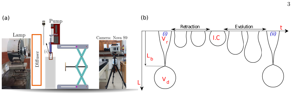
The central discovery is a time-resolved picture of the dripping-jetting transition in Newtonian fluids. For inlet velocities just above the steady-state critical value, the system starts in dripping and repeatedly pinches off droplets while the liquid column attached to the nozzle grows a little after each breakup; eventually the tip velocity of the column exceeds the inlet velocity, the column stops fully recoiling, and the jet appears. In experiments with Kapitza number 0.181 and Bond number 0.067, a dimensionless inlet velocity $U_m = 0.88$ produced roughly fifty dripping pinch-offs before jetting, whereas $U_m = 1.5$ needed only about ten and reached the jet at $t/t_c = 312$ rather than $t/t_c = 888$. The same progressive elongation is reproduced by the slender-jet equations and by full two-phase Navier-Stokes simulations, including the asymmetry of the hysteresis loop: jetting-to-dripping upon reducing flow is a sudden drop rather than a long transient. The paper therefore claims that the quasi-steady phase boundary should be split into two Weber numbers: the lowest Weber number at which jetting eventually appears after a transient, and the higher Weber number at which jetting begins immediately.
Load-bearing premise
The experiments assume that switching on the syringe pump is an instantaneous step in inlet velocity at $t/t_c = 0$, but the pump's flow-rate ramp, tubing compliance, and motor transient are never characterized; if the pump approaches the set flow rate slowly, the observed delay in jetting could be a response to a gradually rising Weber number rather than an intrinsic many-droplet transient at fixed control conditions.
Editorial extensions
If this is right
- The critical Weber number reported for dripping-to-jetting is observation-time dependent; two experiments at the same flow rate can be classified as dripping or jetting depending on whether the recording lasts long enough to include the transient.
- The transient band is wider at low Kapitza numbers and narrows with increasing viscosity, so fluid properties set not only the boundary location but also the delay needed to reach it.
- At the same nominal flow rate the system can display dripping, a mixed regime, or jetting depending on flow history, so the hysteresis in this transition has a temporal dimension, not just a static one.
- Inlet forcing in the dripping-to-jetting band can move the system into either the dripping or the jetting branch, meaning perturbations of suitable amplitude and frequency can stabilize a desired breakup mode.
Reading between the lines
- Editorial extension: if the transition is a slow trajectory on the system's phase space, the number of pre-jetting droplets likely follows a scaling law in the distance from the threshold, such as a power of $(We - We_{d-j})$; the paper reports the trend but does not derive such a law, so this is a testable quantitative prediction.
- Editorial extension: the escape-pinch-off ratchet should also operate in non-Newtonian or viscoelastic fluids, where delayed necking is stronger; repeating the same startup protocol with such fluids would test whether the transient band widens or narrows with relaxation time.
- Editorial extension: in printing and spraying, a controller that perturbs the nozzle near the droplet formation frequency could use the transient band to switch between dripping and jetting on demand; the paper's perturbation phase plots are the raw material for such a control strategy.
Editorial analysis
A structured set of objections, weighed in public.
Referee Report
Summary. The paper reports experiments and simulations of the dripping-to-jetting transition in Newtonian fluids and argues that, at a fixed inlet velocity above the steady-state critical Weber number, the system first produces several droplets in the dripping regime before switching to jetting. The authors support this with high-speed shadowgraphy of several fluids, a 1D slender-jet model, and Gerris volume-of-fluid simulations. They also show that superposed inlet-velocity perturbations can suppress or accelerate the transition. The central claim is that the transition is a history-dependent transient process rather than an instantaneous switch at a critical Weber number.
Significance. If the central claim holds, it refines the standard quasi-steady dripping-jetting phase diagram by identifying a transient transition band in which the number of pre-transition droplets depends on Weber number and fluid properties. This is practically relevant for drop-on-demand and jetting applications where startup transients determine the first produced droplets. A clear strength is that the 1D simulations use standard slender-jet equations with stated initial and boundary conditions and do not fit parameters to produce the phase diagrams; the low-Weber-number comparison in Fig. 8 is also a genuine validation. However, the experimental support is weakened by uncharacterized pump startup and by the absence of trial counts and error bars, and the numerical support is not validated against the transition transient itself. The result is plausible but not yet established at the level claimed.
major comments (4)
- [Section II, Fig. 2] The interpretation of the delayed transition as an intrinsic fixed-Weber-number transient requires the inlet velocity to reach its final value on a time scale much shorter than the droplet period. The Fig. 2 caption states that t/tc = 0 is when the syringe pump is switched on, while the text says the timeline starts at the first pinch-off; moreover, the paper nowhere reports the measured flow-rate transient, tubing compliance, or motor ramp of the NE-1000 pump. Because tc is about 2 ms for this system, a pump settling time of even 0.1 s spans many droplet periods, and if the delivered Weber number crosses the transition threshold only after several pinch-offs, the observed sequence is a quasi-static ramp response rather than a transient at fixed We. Please measure the delivered flow rate at the nozzle (or otherwise characterize the startup transient) and reconcile the time-origin definitions.
- [Section II, Figs. 3 and 7e] The central quantitative claim of 'number of droplets before jetting' is presented without trial counts, error bars, or a statement of how many experimental repetitions each data point represents. Figures 3a and 4 show single representative runs, and the kernel density estimates in Fig. 6 do not report the number of droplets used. Given that the dripping regime is chaotic, a single run cannot establish the mean or the variability of the pre-transition droplet count. Please report repeated runs and the resulting spread, at least for the cases used to define W ed−j and the transition band.
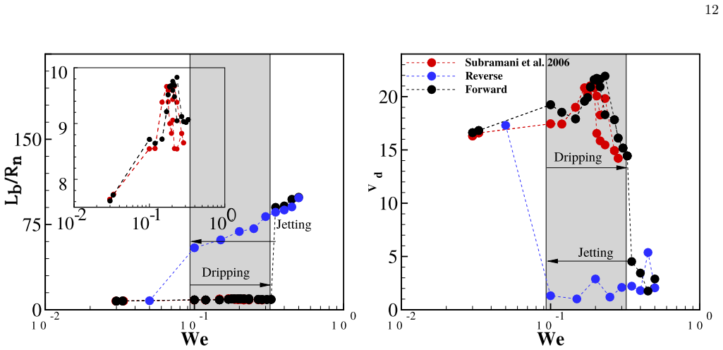
- [Section III, Figs. 8, 10, and 11] The numerical evidence for the delayed transition is not validated against the transient regime it is meant to explain. Fig. 8 validates the 1D model at We = 0.0019, deep in the dripping regime, and Appendix A validates Gerris against P1 and P2 regimes; neither checks the predicted number of pre-transition droplets or the time evolution of L/Rn in the D-J transition band. Because the simulations are the primary evidence that the delay is intrinsic to an ideal velocity step, please compare simulated L/Rn(t) and droplet counts with the experimental transition traces at matched Ka and Bo, for example the Um = 0.88 case of Fig. 3a.
- [Section III, Figs. 12 and 14] The perturbation frequencies are inconsistent between text and captions. The text says 'two frequencies ω = 1.38 and ω = 3.342' and 'For a frequency ω = 1.38 (Figure 12a)', but the Fig. 12 caption labels the panels '(a) ω = 0.342 (b) ω = 1.38', and the later discussion refers to 'ǫ = 0.2, ω = 0.342' and 'ǫ = 0.7, ω = 1.38'. This prevents the reader from reproducing the perturbation phase diagram in Fig. 14 and from assigning regimes correctly. Please correct the labels and ensure the text, captions, and figure axes agree.
minor comments (4)
- [Section II, Figs. 3 and 7] The panel labels in the Fig. 3 caption repeat '(c)' for the Poincare maps, and the Fig. 7 caption repeats '(c)' for the P2 and jetting panels; please renumber them so that each panel is uniquely identified.
- [Throughout] There are several typographical errors: 'Kaptiza number' should be 'Kapitza number', 'For instant' should be 'For instance', 'vis-a-versa' should be 'vice versa', and in Appendix B 'Desnsity' and 'kernal' should be 'Density' and 'kernel'.
- [Section II] The notation for the transition threshold is inconsistent: the abstract and text use U_{m−d_j}, while the figures and later text use W e_{d−j} or W e_{D−J}. Please define all symbols once and use them uniformly.
- [Section III, Eq. (4)] The perturbed inlet condition is written as a(0,t)=1 and u(0,t)=sqrt(We)+epsilon sin(omega t), but the frequency ranges in Fig. 14 are not stated on the axis labels. Please add explicit axis labels and, if possible, a dimensional or dimensionless frequency axis so the reader can connect Fig. 14 to the examples in Fig. 12.
Circularity Check
No significant circularity: delayed jetting emerges from untuned standard slender-jet simulations and direct experiment; the sole self-citation (Gerris solver, Ref. 22) is an externally validated tool and is not load-bearing.
full rationale
The paper's central claim - that beyond a critical Weber number the dripping-to-jetting transition is not instantaneous but occurs only after many pinch-off events in the dripping regime - is an emergent result, not an input. Experiments observe it directly (Section II, Figs. 2-4), and the simulations reproduce it from untuned standard equations: the slender-jet model of Eqs. (1)-(3) (Eggers and Dupont [18]) with a stated hemispherical initial condition and a uniform inlet velocity. No parameter is fitted to produce the droplet counts before jetting (Fig. 10), the Ka-We phase diagram (Fig. 11), or the perturbation phase plot (Fig. 14); amplitudes and frequencies are varied as controls, not fitted to a target outcome. The trend that fewer dripping droplets occur as We increases is confirmed by two independent approaches (experiments, Fig. 3a; Gerris simulation, Fig. 10). The only self-citation is the Gerris solver (Ref. [22], a coauthor), used as a numerical tool and validated against the independent experiments of Subramani et al. [10] (Appendix A, Fig. 15c,d); it is real evidence, not a load-bearing circular premise. Three stated limitations deserve note but are not circularity: (i) the time origin is defined inconsistently between the Fig. 2 caption ('t/tc = 0 corresponding to when the syringe pump is switched on') and the Section II text ('The timeline mentioned in the figure starts from the first droplet pinch-off event'); (ii) the model is validated at low-We dripping (Fig. 8), not at the transition transient itself; (iii) the perturbation frequencies are 'arbitrarily selected with some cues from the formation frequency of droplets' (Section III). These bear on experimental validity and generality, not on whether the derivation reduces to its inputs. The conclusion is not defined in terms of, or fitted to, its own outputs, so the paper is not circular.
Assumptions & free parameters
assumptions (4)
- domain assumption The slender-jet equations (Eqs. 1-3) accurately describe the dripping-to-jetting transition, including pinch-off and transient column growth.
- ad hoc to paper A hemispherical droplet is a sufficient initial condition and contact-angle or wetting effects can be ignored.
- domain assumption The syringe pump delivers a step-change in flow rate at t=0 with no measurable startup transient.
- domain assumption Imposing a uniform velocity profile at the nozzle, plus a sinusoidal perturbation in Eq. 4, reproduces the effect of real inlet perturbations.
Cite this review
Pith. "Pith review of Role of Transient Dynamics in Dripping-Jetting Transition in Newtonian Fluids." pith.science (2026). https://pith.science/paper/XPUCCKSE
@misc{pith2026250706800,
  author       = {Pith},
  title        = {Pith review of: Role of Transient Dynamics in Dripping-Jetting Transition in Newtonian Fluids},
  year         = {2026},
  howpublished = {\url{https://pith.science/paper/XPUCCKSE}},
  note         = {Machine review of arXiv:2507.06800}
}
abstract
Dripping dynamics has been well studied over the past century and forms a classic example of chaotic system in physics. With an increase in the inlet flow rate, periodic droplet formation from a faucet becomes chaotic in terms of the droplet size and the length of the liquid column at the time of pinch-off. With a further increase in the flow rate, dripping regime transitions into jetting regime where the liquid column length is much longer than that observed in the dripping case. In general, dripping faucet is seen as a long time behavior of the system at fixed control parameters. In the steady state condition, different nonlinear behaviors such as periodic and chaotic formation of droplets are observed in the dripping and jetting regimes. It is known that dripping faucet shows chaotic dripping regime before jetting regime ensues. At a critical inlet velocity, $U_{m-d_j}$, we note that dripping to jetting transition occurs after several droplets have formed in the dripping regime. The transition behaviour can be characterized by the time evolution of the liquid jet length $L$ and droplet size $D_p$. Solution to slender jet equation show that the dripping-jetting transition region is a function of the fluid properties. Further, we show that perturbations in the inlet velocity can significantly modify the transient behavior of the dripping to jetting regime transition.
Figures


Figures from the paper (12 more)




Reference graph
Works this paper leans on
-
[1]
Shaw, The Dripping Faucet as a Model Chaotic System (Aerial press, Santa Cruz, 1984)
R. Shaw, The Dripping Faucet as a Model Chaotic System (Aerial press, Santa Cruz, 1984)
work page 1984
-
[2]
P. Coullet, L. Mahadevan, and C. Riera, Journal of Fluid M echanics 526, 1 (2005)
work page 2005
-
[3]
K. Kiyono and N. Fuchikami, Journal of the Physical Socie ty of Japan 68, 3259 (1999)
work page 1999
-
[4]
B. Ambravaneswaran, S. D. Phillips, and O. A. Basaran, Ph ysical review letters 85, 5332 (2000)
work page 2000
- [5]
-
[6]
M. Rubio-Rubio, P. Taconet, and A. Sevilla, Internation al Journal of Multiphase Flow 104, 206 (2018)
work page 2018
-
[7]
M. Rubio-Rubio, A. Sevilla, and J. M. Gordillo, Journal o f Fluid Mechanics 729, 471 (2013)
work page 2013
-
[8]
B. Ambravaneswaran, H. J. Subramani, S. D. Phillips, and O. A. Basaran, Physical review letters 93, 034501 (2004)
work page 2004
Show all 36 references
-
[9]
Eggers and M
J. Eggers and M. A. Fontelos, Singularities: formation, structure, and propagation , Vol. 53 (Cambridge University Press, 2015)
2015
-
[10]
H. J. Subramani, H. K. Yeoh, R. Suryo, Q. Xu, B. Ambravane swaran, and O. A. Basaran, Physics of fluids 18, 032106 (2006)
2006
-
[11]
Zhang and O
X. Zhang and O. A. Basaran, Journal of Fluid Mechanics 326, 239 (1996)
1996
-
[12]
Z. Wang, Y. Zhang, Q. Wang, K. Dong, S. Yang, Y. Jiang, J. Z heng, B. Li, Y. Huo, X. Wang, et al. , Experimental Thermal and Fluid Science 120, 110250 (2021)
2021
-
[13]
Zhang and O
X. Zhang and O. A. Basaran, Physics of fluids 7, 1184 (1995)
1995
-
[14]
Zhang, Chemical Engineering Science 54, 1759 (1999)
X. Zhang, Chemical Engineering Science 54, 1759 (1999)
1999
-
[15]
Ambravaneswaran, E
B. Ambravaneswaran, E. D. Wilkes, and O. A. Basaran, Phy sics of Fluids 14, 2606 (2002)
2002
-
[16]
Umemura, Journal of Fluid Mechanics 797, 146 (2016)
A. Umemura, Journal of Fluid Mechanics 797, 146 (2016)
2016
-
[17]
Hoepffner and G
J. Hoepffner and G. Par´ e, Journal of fluid mechanics 734, 183 (2013)
2013
-
[18]
Eggers and T
J. Eggers and T. F. Dupont, Journal of fluid mechanics 262, 205 (1994)
1994
-
[19]
Shukla and F
I. Shukla and F. Gallaire, Journal of Fluid Mechanics 894 (2020)
2020
-
[20]
Popinet, Journal of Computational Physics 190, 572 (2003)
S. Popinet, Journal of Computational Physics 190, 572 (2003)
2003
-
[21]
Popinet, Journal of Computational Physics 228, 5838 (2009)
S. Popinet, Journal of Computational Physics 228, 5838 (2009)
2009
-
[22]
Tomar, D
G. Tomar, D. Fuster, S. Zaleski, and S. Popinet, Compute rs & Fluids 39, 1864 (2010)
2010
-
[23]
Ambravaneswaran, Deformation and breakup of drops and filaments , Ph.D
B. Ambravaneswaran, Deformation and breakup of drops and filaments , Ph.D. thesis, Purdue University (2000)
2000
-
[24]
Villermaux, V
E. Villermaux, V. Pistre, and H. Lhuissier, Journal of F luid Mechanics 730, 607 (2013)
2013
-
[25]
C. R. Anthony, H. Wee, V. Garg, S. S. Thete, P. M. Kamat, B. W. Wagoner, E. D. Wilkes, P. K. Notz, A. U. Chen, R. Suryo, et al. , Annual Review of Fluid Mechanics 55, 707 (2023)
2023
-
[26]
Safronov, A
A. Safronov, A. Koroteev, N. Filatov, and N. Bondareva, Thermophysics and Aeromechanics 28, 237 (2021)
2021
-
[27]
Sartorelli, W
J. Sartorelli, W. Gon¸ calves, and R. Pinto, Physical Re view E 49, 3963 (1994). 18
1994
-
[28]
S. P. Lin and R. D. Reitz, Annual review of fluid mechanics 30, 85 (1998)
1998
-
[29]
Trettel, Atomization and Sprays 30 (2020)
B. Trettel, Atomization and Sprays 30 (2020)
2020
-
[30]
Rezayat, M
S. Rezayat, M. Farshchi, and E. Berrocal, Internationa l Journal of Multiphase Flow 145, 103807 (2021)
2021
-
[31]
Umemura, Physical Review E 83, 046307 (2011)
A. Umemura, Physical Review E 83, 046307 (2011)
2011
-
[32]
Li and J
Y. Li and J. E. Sprittles, Journal of Fluid Mechanics 797, 29 (2016)
2016
-
[33]
Sedighi, Z
E. Sedighi, Z. Zeng, A. Sadeghpour, H. Ji, Y. S. Ju, and A. L. Bertozzi, Langmuir 37, 10413 (2021)
2021
-
[34]
Moallemi, R
N. Moallemi, R. Li, and K. Mehravaran, Physics of Fluids 28 (2016)
2016
-
[35]
McIlroy and O
C. McIlroy and O. G. Harlen, Physics of Fluids 31 (2019)
2019
-
[36]
J. U. Brackbill, D. B. Kothe, and C. Zemach, Journal of co mputational physics 100, 335 (1992)
1992
Reviewed August 6, 2026 · model on record in the stance chip above.
Discussion (0). Continue with ORCID to comment.