REVIEW 3 major objections 5 minor 33 references
A RIS-Enabled Computational Radar Coincidence Imaging
T0 review · 3 major / 5 minor · reviewed 2026-08-06 · deepseek-v4-flash
Pith's one-line read The paper claims that forming speckle patterns from directive RIS beams, rather than from random patterns, yields higher SNR, lower clutter, and high-quality images from fewer measurements than raster scanning.
desk verdict A real and clearly explained new combination of RCI-style coincidence imaging with directive-beam speckle on RISs, but the SNR/clutter/few-measurement claims rest on an inverse-crime simulation that needs to be addressed before the results can be believed. read the letter →
The pith
A machine-rendered reading of the paper's core claim, the machinery that carries it, and where it could break.
The reading
What carries the argument
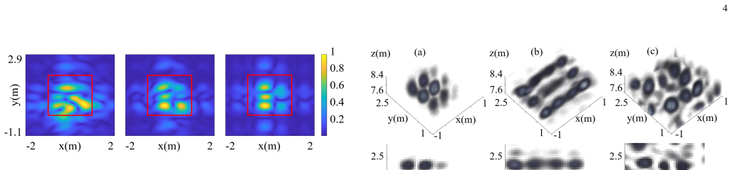
The central object is the focused speckle pattern: the coherent interference of several RIS-radiated directive beams, all steered into the same ROI but each carrying a random phase offset and a random perturbation of its redirection angles $\theta$ and $\phi$ chosen to keep the beam inside the ROI. Each such configuration is called a mask; changing the mask changes the speckle pattern, and sweeping frequency from 5.9 to 6.1 GHz adds diversity and range information. The sensing matrix is computed from simulated fields at every pixel, and the same simulator is reused to build the inverse matrix used for reconstruction; an SVD analysis shows that phase offsets alone exhaust pattern diversity once the number of measurements exceeds the product of the number of Tx and Rx RISs, while randomizing the redirection angles extends the pattern rank.
What would settle it
Measure the complex fields radiated by the six transmit and six receive RIS panels in an anechoic chamber, build the inverse sensing matrix from those measured fields, and run the same 100-measurement reconstruction of a 3-by-3 scatterer grid at 20 dB SNR. If the nine scatterers are no longer resolved, or if a clutter object at y = 3 m visibly corrupts the image, the claimed few-measurement and clutter-rejection advantages do not survive contact with a real device.
Extended reading notes
Core claim
The paper's central claim is that focused speckle patterns encode the reflectivity of the whole ROI in a few measurements while retaining the SNR and clutter rejection of directive beams. Under the first-Born (single-scattering) approximation, the measured signal is $g = H_{\mathrm{FWD}} \sigma$, with $h(i,j) = E_{\mathrm{Tx}}^{(i)}(\mathbf{r}_j) \cdot E_{\mathrm{Rx}}^{(i)}(\mathbf{r}_j)$, and the inverse problem is solved computationally using an inverse sensing matrix built from the same simulator. In simulations with five frequency points from 5.9 to 6.1 GHz and 20 masks (100 measurements) at 20 dB SNR, the method resolves a 3-by-3 grid of subwavelength scatterers at z = 8 m, while raster scanning aliases and random-pattern imaging is noise-dominated. With a clutter object at y = 3, 5, or 10 m, the proposed reconstruction stays clean while the random-pattern reconstruction degrades.
Load-bearing premise
The load-bearing premise is that the inverse sensing matrix is computed from the same ideal simulator that generated the data, so the numerical test contains none of the real-world discrepancies, such as mutual coupling, phase quantization, calibration error, or unmodeled scattering, that would make the simulated and actual RIS fields differ.
Editorial extensions
If this is right
- An RIS-based imager can reconstruct a 2D region of interest with fewer measurements than raster scanning, because computational inversion fills in spatial frequencies that are not directly sampled.
- Concentrating the radiated power into the ROI raises the signal-to-noise ratio relative to random-pattern computational imaging at the same transmit power.
- Out-of-region clutter contributes less to the reconstruction, so imaging in crowded areas such as security checkpoints or rooms with moving people should become more reliable.
- The same hardware can switch to a different ROI simply by recomputing the redirection angles and phase offsets, with no mechanical movement.
- Adding more frequency points extends the approach toward range resolution, a natural path from 2D reflectivity maps to 3D volumetric images.
Reading between the lines
- The paper does not state this, but a direct hardware test should compare the singular-value spectrum of the measured sensing matrix with the simulated one; if angle randomization no longer extends the rank beyond the phase-offset plateau, the few-measurement advantage will not transfer to practice.
- The random perturbation range $C_\theta, C_\phi$ sets a resolution-vs-diversity tradeoff: wider perturbations spread energy toward the ROI edges, so an optimal distribution could be tuned per ROI, a knob the paper leaves unexplored.
- The same focused-speckle mechanism could serve real-time user tracking by reconstructing a coarse reflectivity map from very few masks, since locating a person requires less spatial detail than resolving fine scatterers.
- Because the illumination is confined to the ROI, the approach may also reduce scattered power from moving objects outside the ROI, which could make privacy-preserving through-wall sensing more practical than random-pattern alternatives.
Signed reviews
Editorial analysis
A structured set of objections, weighed in public.
Referee Report
Summary. The paper proposes a microwave imaging method that combines radar coincidence imaging (RCI) with computational imaging using reconfigurable intelligent surfaces (RISs). Multiple RISs redirect signals from a transmitter toward a region of interest, and the interference of the resulting directive beams forms speckle-like patterns that encode the reflectivity of the ROI. The authors argue that because the speckle patterns are formed by directive beams rather than fully random patterns, the method enjoys higher SNR and reduced clutter, while still allowing high-quality reconstruction from fewer measurements than raster scanning. The forward model assumes ideal lossless RIS elements with continuous phase control, no mutual coupling, and perfect knowledge of the sensing matrix. Numerical simulations compare the proposed method with raster scanning and random-pattern approaches for a 2D target at 8 m, including a clutter robustness study. The paper concludes that the method combines the benefits of spotlight and computational imaging and suggests applications in security screening and user tracking.
Significance. If validated, the proposed concept would be a useful contribution to RIS-enabled computational imaging, as it directly addresses the SNR and clutter limitations of random-pattern metasurface imagers while retaining the few-measurement advantage of computational imaging. The idea of confining speckle diversity to a predefined ROI via multiple directive beams is conceptually sound and grounded in prior computational imaging and RCI work. The SVD analysis of pattern diversity (Fig. 7) is a sensible design tool, and the qualitative comparisons in Figs. 10 and 11 are suggestive. However, the numerical demonstration currently rests on a self-consistent ideal simulator: the inverse sensing matrix is computed from the same ideal model that generates the simulated measurements, constituting an inverse-crime setup. The absence of quantitative metrics, Monte Carlo statistics, and forward-model mismatch tests means that the central claims of improved SNR, clutter robustness, and few-measurement performance are not yet convincingly established. The paper also provides no experimental or realistic error model.
major comments (3)
- [§II, Eqs. (4) and (2)] The numerical demonstration commits an inverse crime: the measured data are generated by evaluating the forward sensing matrix HFWD from Eq. (4), while the inverse matrix HINV is computed 'for the same M measurement configurations, in a similar manner as in equation (2),' i.e., from the same ideal simulator. This means the inversion operator is perfectly matched to the data-generation operator, leaving no modeling error. In practice, RIS element phase errors, mutual coupling, phase quantization, and unmodeled scattering will make the true sensing matrix differ from HINV, and the claimed few-measurement and clutter advantages, as shown in Figs. 10 and 11, are upper bounds that may not transfer to experiment. The authors' note that phase quantization 'would degrade all methods' does not address this issue, because the proposed method's advantage specifically relies on precise knowledge of the focused speckle pattern. Please add experiments with model mismatch, for example by perturbing the RIS phase profiles, introducing element coupling, or using a different forward simulator to generate data than the one used for inversion, and report how reconstruction quality degrades.
- [Figs. 10 and 11] The paper relies entirely on qualitative visual comparisons and contains no quantitative image-quality metric (e.g., normalized mean-square error, peak signal-to-noise ratio, or resolution) and no Monte Carlo averaging over noise or mask realizations. The abstract and introduction claim 'higher SNR' and 'reduced clutter,' but the manuscript does not define how SNR is computed or quantify the improvement over random patterns. The clutter study in Fig. 11 uses a single realization at each clutter location and a high 50 dB SNR, which is not representative of realistic conditions. Please provide quantitative metrics over multiple noise and clutter realizations, and clearly define the SNR used in the simulations, so that the claimed advantages can be assessed rather than inferred from example images.
- [§II, description of the inverse model] The inverse problem is solved with a computational technique identified only as 'CGS' (conjugate gradient squared?) but the manuscript gives no details about the number of iterations, stopping criterion, regularization, or the discretization grid (number of voxels N, pixel size, etc.). Since the central claim is that high-quality images are obtained with M < N, it is essential to report these parameters to assess whether the success is due to the proposed patterns or to the specific inversion implementation. Please specify the reconstruction algorithm, regularization, and grid parameters, and consider showing performance as a function of measurement number M for a range of target configurations.
minor comments (5)
- [General / Eq. numbering] The equation numbering is inconsistent: Eq. (4) is introduced before Eq. (2), and Eq. (2) is used both for the redirection-angle random component and for the forward sensing matrix element. Please renumber the equations sequentially to avoid confusion.
- [§II, first paragraph] There is a typo in 'a an array of 20 × 20 elements.' Also, the sentence 'To implement random patterns, we assign a random phase to each element of the RIS' in §II could be clarified by stating whether the random-phase patterns are used for both Tx and Rx RISs and whether the same random patterns are used across frequency points.
- [§II, Fig. 7] The SVD analysis is presented as a design-motivating result, but the figure caption does not explain how the SVD of the 'patterns' is computed (e.g., is it the singular values of the sensing matrix for a fixed ROI?). Please clarify the exact quantity being decomposed and describe how the SVD curves support the choice of 20 masks.
- [§II, raster scanning description] In the raster scanning description, the text says 'direct the beam toward a given location inside the RIS,' which should presumably read 'inside the ROI.' Please correct this and specify the scan grid and whether scanning is performed over all six Tx/Rx RIS pairs simultaneously.
- [Reproducibility] The manuscript does not state the pixel count, ROI discretization, or the exact frequency sampling scheme beyond 'five frequency points ranging from 5.9 GHz to 6.1 GHz.' Please include these values so that the simulations can be reproduced.
Circularity Check
Inverse crime in the numerical demonstration: HINV is computed from the same ideal simulator that generated the data, so the few-measurement and clutter claims are self-consistent simulation results rather than model-robust predictions.
-
other
[Section II, forward/inverse models (Eq. (4) and the paragraph defining HINV)]
"The forward sensing matrix HFWD is computed by evaluating the fields generated by the RISs at each pixel location: hfwd(i, j) = E_i_Tx(r_j) . E_i_Rx(r_j), (2) ... In the inverse model, we discretize the ROI around the target into N voxels and computed the inverse sensing matrix, HINV M x N, for the same M measurement configurations, in a similar manner as in equation (2)."
The synthetic measurements are generated by g = HFWD sigma (Eq. (4)), where HFWD is evaluated from ideal RIS field products at each pixel. HINV is then constructed 'for the same M measurement configurations, in a similar manner as in equation (2),' meaning the inversion operator is built from the same ideal field model as the data-generation operator. The reconstruction therefore faces zero forward-model mismatch; the few-measurement and clutter reconstructions in Figs. 10 and 11 certify only that the CGS solver can invert a perfectly known linear system, not that the method is robust to real RIS phase errors, mutual coupling, or calibration uncertainty.
full rationale
The paper's central algorithmic idea is not itself circular: the forward model is a standard Born-approximation scattering model, the phase-gradient masks are defined independently of the target, and the CGS reconstruction is a genuine inverse problem with M<N and additive noise. However, the numerical validation is compromised by an inverse crime: the synthetic data are generated by HFWD, which evaluates ideal RIS fields at pixels, and HINV is computed from the same ideal field model for the same measurement configurations. Thus the high-quality images in Figs. 10 and 11 reflect self-consistency of the simulator rather than robustness to real RIS non-idealities. The paper's limitation statement acknowledges that 'phase quantization and other losses can result in beam quality degradation' but asserts these 'would degrade all methods'; that assertion does not address the inverse crime, because the comparison is performed with zero model mismatch. The self-citation to the authors' prior conference paper [31] is not load-bearing, since the present manuscript contains the full numerical derivation and comparison. No fitted parameters are renamed as predictions, and no uniqueness theorem is imported from the authors' prior work. The score reflects one central methodological circularity in the numerical demonstration, not a logical equivalence of the whole derivation.
Assumptions & free parameters
free parameters (2)
- Beam confinement scaling factors C_theta, C_phi =
random values drawn between 0 and 0.25; not optimized in the paper
- Random phase offsets added per RIS =
unspecified random phases, one per RIS and mask
assumptions (4)
- domain assumption First-Born approximation: measured signal is a linear function of reflectivity, g = H sigma.
- ad hoc to paper Ideal RIS model: lossless varactor phase shifters with continuous full-range phase and no element coupling.
- ad hoc to paper Perfect model knowledge for inversion: H_INV is computed from the same ideal simulator as H_FWD.
- domain assumption Known target location and dense discretization of the target in the forward model.
Cite this review
Pith. "Pith review of A RIS-Enabled Computational Radar Coincidence Imaging." pith.science (2026). https://pith.science/paper/FWK4HQXH
@misc{pith2026250707285,
  author       = {Pith},
  title        = {Pith review of: A RIS-Enabled Computational Radar Coincidence Imaging},
  year         = {2026},
  howpublished = {\url{https://pith.science/paper/FWK4HQXH}},
  note         = {Machine review of arXiv:2507.07285}
}
read the original abstract
This paper introduces an innovative imaging method using reconfigurable intelligent surfaces (RISs) by combining radar coincidence imaging (RCI) and computational imaging techniques. In the proposed framework, RISs simultaneously redirect beams toward a desired region of interest (ROI). The interference of these beams forms spatially diverse speckle patterns that carry information about the entire ROI. As a result, this method can take advantage of the benefits of both random patterns and spotlight imaging. Since the speckle pattern is formed by directive beams (instead of random patterns typically used in computational imaging), this approach results in a higher signal-to-noise ratio (SNR) and reduced clutter. In contrast to raster scanning, which requires the number of measurements to be at least equal to the number of unknowns, our proposed approach follows a computational imaging framework and can obtain high-quality images even when only a few measurements are taken. Using numerical simulation, we demonstrate this method's capabilities and contrast it against other conventional techniques. The proposed imaging approach can be applied to security screening, wireless user tracking, and activity recognition.
Figures


Figures from the paper (4 more)



Reference graph
Works this paper leans on
-
[1]
Soumekh, Fourier array imaging
M. Soumekh, Fourier array imaging. Prentice-Hall, Inc., 1994
work page 1994
-
[2]
Three-dimensional millimeter-wave imaging for concealed weapon detection,
D. M. Sheen, D. L. McMakin, and T. E. Hall, “Three-dimensional millimeter-wave imaging for concealed weapon detection,” IEEE Trans- actions on microwave theory and techniques , vol. 49, no. 9, pp. 1581– 1592, 2001
work page 2001
-
[3]
Intelligent metasurface imager and recognizer,
L. Li, Y . Shuang, Q. Ma, H. Li, H. Zhao, M. Wei, C. Liu, C. Hao, C.- W. Qiu, and T. J. Cui, “Intelligent metasurface imager and recognizer,” Light: science & applications , vol. 8, no. 1, p. 97, 2019
work page 2019
-
[4]
A review of microwave wireless techniques for human presence detection and classification,
J. A. Nanzer, “A review of microwave wireless techniques for human presence detection and classification,” IEEE Transactions on Microwave Theory and Techniques, vol. 65, no. 5, pp. 1780–1794, 2017
work page 2017
-
[5]
Microwave imaging in security—two decades of innova- tion,
S. S. Ahmed, “Microwave imaging in security—two decades of innova- tion,” IEEE Journal of Microwaves , vol. 1, no. 1, pp. 191–201, 2021
work page 2021
-
[6]
Development of a high-throughput microwave imaging system for concealed weapons detection,
W. F. Moulder, J. D. Krieger, J. J. Majewski, C. M. Coldwell, H. T. Nguyen, D. T. Maurais-Galejs, T. L. Anderson, P. Dufilie, and J. S. Herd, “Development of a high-throughput microwave imaging system for concealed weapons detection,” in 2016 IEEE International Symposium on Phased Array Systems and Technology (PAST), pp. 1–6, IEEE, 2016
work page 2016
-
[7]
Radar handbook, (mi skolnik, ed; 2008)[book review],
F. Daum, “Radar handbook, (mi skolnik, ed; 2008)[book review],” IEEE Aerospace and Electronic Systems Magazine , vol. 23, no. 5, pp. 41–41, 2008
work page 2008
-
[8]
Compressed sensing,
D. L. Donoho, “Compressed sensing,” IEEE Transactions on information theory, vol. 52, no. 4, pp. 1289–1306, 2006
2006
Show all 33 references
-
[9]
Large metasurface aperture for millimeter wave computational imaging at the human-scale,
J. Gollub, O. Yurduseven, K. P. Trofatter, D. Arnitz, M. F. Imani, T. Sleasman, M. Boyarsky, A. Rose, A. Pedross-Engel, H. Odabasi, et al. , “Large metasurface aperture for millimeter wave computational imaging at the human-scale,” Scientific reports, vol. 7, no. 1, p. 42650, 2017
2017
-
[10]
Review of metasurface antennas for computational microwave imag- ing,
M. F. Imani, J. N. Gollub, O. Yurduseven, A. V . Diebold, M. Boyarsky, T. Fromenteze, L. Pulido-Mancera, T. Sleasman, and D. R. Smith, “Review of metasurface antennas for computational microwave imag- ing,” IEEE transactions on antennas and propagation , vol. 68, no. 3, pp. 18...
2020
-
[11]
A high-speed programmable and scalable terahertz holographic metasurface based on tiled cmos chips,
S. Venkatesh, X. Lu, H. Saeidi, and K. Sengupta, “A high-speed programmable and scalable terahertz holographic metasurface based on tiled cmos chips,” Nature electronics, vol. 3, no. 12, pp. 785–793, 2020
2020
-
[12]
Smart radio environments empowered by recon- figurable ai meta-surfaces: An idea whose time has come,
M. D. Renzo, M. Debbah, D.-T. Phan-Huy, A. Zappone, M.-S. Alouini, C. Yuen, V . Sciancalepore, G. C. Alexandropoulos, J. Hoydis, H. Gacanin, et al. , “Smart radio environments empowered by recon- figurable ai meta-surfaces: An idea whose time has come,” EURASIP Journal on Wire...
2019
-
[13]
Wireless communications through reconfigurable intelligent surfaces,
E. Basar, M. Di Renzo, J. De Rosny, M. Debbah, M.-S. Alouini, and R. Zhang, “Wireless communications through reconfigurable intelligent surfaces,” IEEE access, vol. 7, pp. 116753–116773, 2019
2019
-
[14]
Applications of absorptive reconfig- urable intelligent surfaces in interference mitigation and physical layer security,
F. Wang and A. L. Swindlehurst, “Applications of absorptive reconfig- urable intelligent surfaces in interference mitigation and physical layer security,” IEEE Transactions on Wireless Communications , 2023
2023
-
[15]
Reconfigurable intelligent surfaces for wireless communica- tions: Principles, challenges, and opportunities,
M. A. ElMossallamy, H. Zhang, L. Song, K. G. Seddik, Z. Han, and G. Y . Li, “Reconfigurable intelligent surfaces for wireless communica- tions: Principles, challenges, and opportunities,” IEEE Transactions on Cognitive Communications and Networking, vol. 6, no. 3, pp. 990–1002, 2020
2020
-
[16]
Design and evaluation of reconfigurable intelligent surfaces in real- world environment,
G. C. Trichopoulos, P. Theofanopoulos, B. Kashyap, A. Shekhawat, A. Modi, T. Osman, S. Kumar, A. Sengar, A. Chang, and A. Alkhateeb, “Design and evaluation of reconfigurable intelligent surfaces in real- world environment,”IEEE Open Journal of the Communications Society, vol. ...
2022
-
[17]
Overview of ris-enabled secure transmission in 6g wireless networks,
J. Bae, W. Khalid, A. Lee, H. Lee, S. Noh, and H. Yu, “Overview of ris-enabled secure transmission in 6g wireless networks,” Digital Communications and Networks , 2024
2024
-
[18]
Secure wireless communication in active ris-assisted dfrc system,
Y . Zhang, H. Ren, C. Pan, B. Wang, Z. Yu, R. Weng, T. Wu, and Y . He, “Secure wireless communication in active ris-assisted dfrc system,” arXiv preprint arXiv:2402.02122 , 2024
2024 arXiv
-
[19]
A reconfigurable intelligent surface with integrated sensing capability,
I. Alamzadeh, G. C. Alexandropoulos, N. Shlezinger, and M. F. Imani, “A reconfigurable intelligent surface with integrated sensing capability,” Scientific reports, vol. 11, no. 1, p. 20737, 2021
2021
-
[20]
Ris-aided wireless communications: Prototyping, adaptive beamforming, and indoor/outdoor field trials,
X. Pei, H. Yin, L. Tan, L. Cao, Z. Li, K. Wang, K. Zhang, and E. Bj¨ornson, “Ris-aided wireless communications: Prototyping, adaptive beamforming, and indoor/outdoor field trials,” IEEE Transactions on Communications, vol. 69, no. 12, pp. 8627–8640, 2021
2021
-
[21]
Wireless localization with space-time coded reconfigurable intelligent surfaces,
M. Gholami, S. Khajavi, M. Neshat, S. Tewes, and A. Sezgin, “Wireless localization with space-time coded reconfigurable intelligent surfaces,” IEEE Transactions on Antennas and Propagation, no. 99, pp. 1–1, 2025
2025
-
[22]
Re- alization of reconfigurable intelligent surfaces with space-time coded metasurfaces,
M. Gholami, S. Khajavi, M. Neshat, S. Tewes, and A. Sezgin, “Re- alization of reconfigurable intelligent surfaces with space-time coded metasurfaces,” arXiv preprint arXiv:2410.20503 , 2024
2024 arXiv
-
[23]
Single-shot and single-sensor high/super-resolution microwave imaging based on metasurface,
L. Wang, L. Li, Y . Li, H. C. Zhang, and T. J. Cui, “Single-shot and single-sensor high/super-resolution microwave imaging based on metasurface,” Scientific reports, vol. 6, no. 1, p. 26959, 2016
2016
-
[24]
Distributed computational imaging with reconfig- urable intelligent surface,
Y . Tao and Z. Zhang, “Distributed computational imaging with reconfig- urable intelligent surface,” in 2020 International Conference on Wireless Communications and Signal Processing (WCSP) , pp. 448–454, IEEE, 2020
2020
-
[25]
Near field computational imaging with ris generated virtual masks,
Y . Jiang, F. Gao, Y . Liu, S. Jin, and T. Cui, “Near field computational imaging with ris generated virtual masks,” IEEE Transactions on An- tennas and Propagation , 2024
2024
-
[26]
Intelligent electromagnetic metasurface camera: system design and experimental results,
Z. Wang, H. Zhang, H. Zhao, T. J. Cui, and L. Li, “Intelligent electromagnetic metasurface camera: system design and experimental results,” Nanophotonics, vol. 11, no. 9, pp. 2011–2024, 2022
2011
-
[27]
Dreamer: Dual-ris-aided imager in complementary modes,
F. Wang, Y . Huang, Z. Feng, R. Xiong, Z. Li, C. Wang, T. Mi, R. C. Qiu, and Z. Ling, “Dreamer: Dual-ris-aided imager in complementary modes,” IEEE Transactions on Antennas and Propagation , 2025
2025
-
[28]
Active ris vs. passive ris: Which will prevail in 6g?,
Z. Zhang, L. Dai, X. Chen, C. Liu, F. Yang, R. Schober, and H. V . Poor, “Active ris vs. passive ris: Which will prevail in 6g?,”IEEE Transactions on Communications, vol. 71, no. 3, pp. 1707–1725, 2022
2022
-
[29]
Phaseless radar coin- cidence imaging with a mimo sar platform,
A. V . Diebold, M. F. Imani, and D. R. Smith, “Phaseless radar coin- cidence imaging with a mimo sar platform,” Remote Sensing , vol. 11, no. 5, p. 533, 2019
2019
-
[30]
Synthetic aperture radar with dynamic metasurface antennas: a conceptual development,
M. Boyarsky, T. Sleasman, L. Pulido-Mancera, T. Fromenteze, A. Pedross-Engel, C. M. Watts, M. F. Imani, M. S. Reynolds, and D. R. Smith, “Synthetic aperture radar with dynamic metasurface antennas: a conceptual development,” JOSA A, vol. 34, no. 5, pp. A22–A36, 2017
2017
-
[31]
A novel computational imaging method using reconfigurable intelligent surfaces,
K. Zirak and M. F. Imani, “A novel computational imaging method using reconfigurable intelligent surfaces,” in 2025 United States National Committee of URSI National Radio Science Meeting (USNC-URSI NRSM), pp. 381–382, IEEE, 2025
2025
-
[32]
Spatially resolving antenna arrays using frequency diversity,
D. L. Marks, J. Gollub, and D. R. Smith, “Spatially resolving antenna arrays using frequency diversity,” Journal of the Optical Society of America A, vol. 33, no. 5, pp. 899–912, 2016
2016
-
[33]
Comprehensive simulation platform for a metamaterial imaging system,
G. Lipworth, A. Rose, O. Yurduseven, V . R. Gowda, M. F. Imani, H. Odabasi, P. Trofatter, J. Gollub, and D. R. Smith, “Comprehensive simulation platform for a metamaterial imaging system,” Applied optics, vol. 54, no. 31, pp. 9343–9353, 2015
2015
Reviewed August 6, 2026 · model on record in the stance chip above.
Discussion (0). Continue with ORCID to comment.