REVIEW 3 major objections 6 minor 36 references
Modeling of the positron sources: an experiment-based benchmarking
T0 review · 3 major / 6 minor · reviewed 2026-08-06 · deepseek-v4-flash
Pith's one-line read A start-to-end simulation chain reproduces the SuperKEKB positron yield to within 0.02%, and matches experimental scans of solenoid field, impact position, and RF phase.
desk verdict Solid start-to-end model with a strong nominal yield match, but the RF-phase scan's 30% discrepancy shows the unmodeled solenoid dipole is a real limitation. read the letter →
The pith
A machine-rendered reading of the paper's core claim, the machinery that carries it, and where it could break.
The reading
What carries the argument
The load-bearing object is the two-stage simulation chain: Geant4 (version 11.2.2, FTFP_BERT physics list) handles electromagnetic shower development and positron production in the target, while RF-Track (version 2.3.2) integrates the equations of motion in time using a fourth-order Runge-Kutta scheme with a converged step of 0.25 mm/c and cubic interpolation of the RF fields, which are generated with SuperFish. The flux concentrator's measured 3.5 T-to-0.4 T tapered field and the DC solenoid channel provide the focusing that determines the transverse-momentum cooling and longitudinal bunching, and the model's treatment of these fields is what makes the yield prediction possible.
What would settle it
Include the measured dipole field of the DC solenoid windings in the RF-Track model and re-run the 1D RF-phase scan at acceleration phases ($\phi_{\text{offset}} \approx 270^\circ$): if the simulated yield stays near 0.6 instead of moving toward the measured 0.46, the nominal 0.02% agreement is not robust to the model's known inaccuracies.
Extended reading notes
Core claim
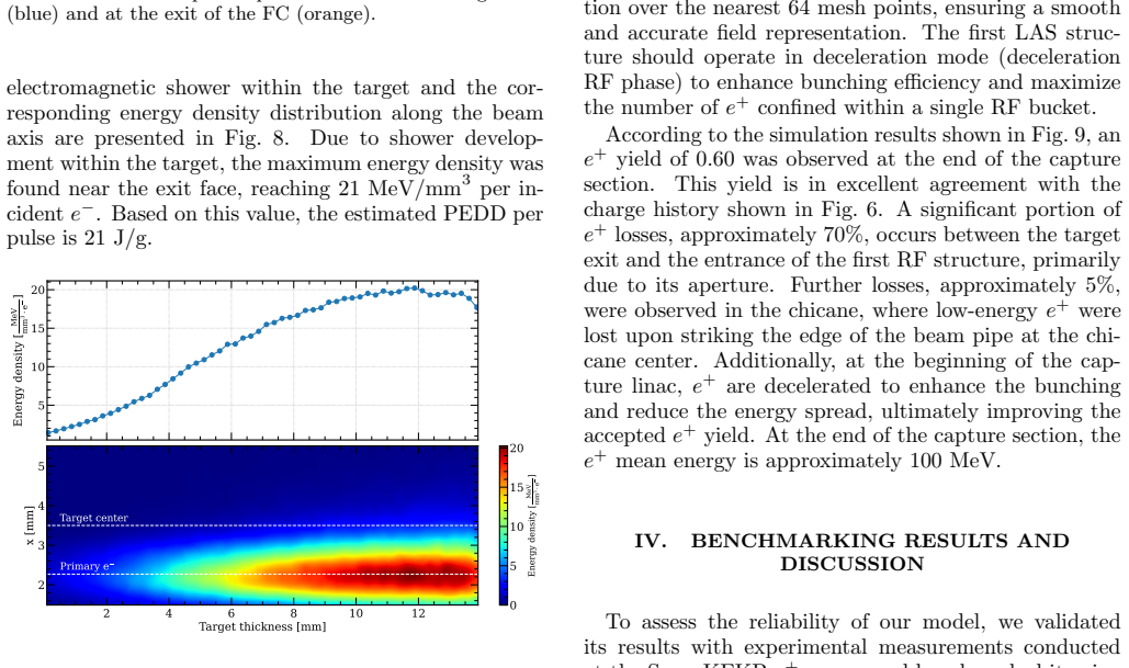
The central claim is that the coupled Geant4 + RF-Track model is a reliable start-to-end simulation framework for high-intensity positron sources, validated experimentally at SuperKEKB. The model simulates the full chain: a 2.9 GeV primary electron beam is tracked through the upstream steering magnets, imported into Geant4 to produce electron-positron pairs in the 14 mm tungsten target and to score the energy deposition (peaking at 21 MeV/mm$^3$ per incident electron), and the emerging positrons are re-imported into RF-Track, which transports them through the flux concentrator and the six LAS structures of the capture linac. The figure of merit is the positron yield after the chicane, and the benchmark scans show that the model reproduces the measured yield's dependence on solenoid field, impact position, and RF phase, although a discrepancy appears in the acceleration half of the RF-phase scan. The authors attribute part of that discrepancy to the idealized magnetic-field model, specifically a dipole component from the DC solenoid windings that is not simulated.
Load-bearing premise
The simulated magnetic fields of the capture-linac DC solenoids are taken as ideal, without the dipole component arising from the hollow-conductor winding and without alignment errors; the paper itself says this omission partly explains the RF-phase scan discrepancy, so if that field error is large the nominal-point agreement may not persist.
Editorial extensions
If this is right
- A validated start-to-end toolchain can predict the accepted positron yield and momentum spread for future sources (e.g., FCC-ee, ILC, CLIC) without the need for a running high-intensity facility to iterate on.
- The 1D RF-phase scan along the diagonal of the 2D phase map is sufficient for practical optimization, because the yield is maximized when the two klystron phases are nearly equal.
- Operating the first capture-linac structures in deceleration mode reduces the momentum spread (21.1 MeV/c vs 44.2 MeV/c at the yield-maximizing phase) and thereby increases the number of positrons accepted into the damping ring, even though the post-chicane yield is lower.
- The model's prediction that almost no positrons reach the end of the capture section without the DC solenoid field quantifies the critical role of the solenoid channel.
- The energy-deposition and PEDD scoring (21 J/g at nominal conditions) can set cooling and target-lifetime requirements in the design phase.
Reading between the lines
- If the nominal 0.02% agreement is not partly fortuitous, extending the model to include the measured dipole component of the solenoid windings and alignment errors should also close the gap at acceleration phases, where simulation predicts 0.6 against 0.46 measured; this is a testable prediction.
- The same zero-crossing-phase calibration technique (using a high-dispersion BPM and a cosine fit) could be adopted as a standard tool for phasing capture sections in other accelerators.
- Because the yield profile along the horizontal impact position is flat within 1.5-2 mm, the simulation suggests that a misalignment tolerance of about one beam size can be allowed in the target-FC assembly, which is useful guidance for mechanical tolerances in new designs.
- The paper's framework may be transferable to the hybrid crystal-based positron source proposed for FCC-ee, where Geant4's production modeling would be the same and RF-Track would only need the new target geometry and field maps.
Editorial analysis
A structured set of objections, weighed in public.
Referee Report
Summary. The paper presents a start-to-end simulation framework for positron sources, coupling Geant4 for pair-production in the tungsten target with RF-Track for 6D beam-dynamics tracking through the capture section and linac. The model is applied to the SuperKEKB positron source and benchmarked against two independent tools (EGS5+GPT and Geant4+ASTRA) and against experimental measurements. Three operational parameters are scanned: DC-solenoid field strength, primary-electron impact position on the target, and RF phases of the capture-linac klystrons. At the nominal working point the simulated positron yield is 0.6034 versus a measured 0.6033 Ne+/Ne-, a 0.02% difference; the paper claims this validates the framework and establishes its applicability to future positron source designs.
Significance. If the validation holds, this would be a valuable experimentally benchmarked start-to-end tool for FCC-ee, ILC, CEPC, and CLIC positron source studies. The work has real strengths: the target yield is not fitted; simulation inputs are taken from measured operational settings; the target geometry, including the offset copper holder and beam hole, is modeled in detail; and comparisons are made against two independent simulation chains. The PEDD estimate of 21 J/g is a useful byproduct. However, the RF-phase scan shows a systematic discrepancy in the acceleration half that the authors attribute to an unmodeled solenoid dipole and idealized layout; this limits the generality of the validation until the effect is quantified.
major comments (3)
- [Sec. IV.C, Fig. 17] The acceleration-mode half of the one-dimensional RF phase scan shows a large systematic discrepancy: the Geant4+RF-Track simulation yields about 0.60 while the measurement is about 0.46, a roughly 30% overestimate. The text attributes this 'partly' to an idealized layout that omits alignment errors and, in particular, an extra dipole component from the DC solenoid winding, but no quantitative estimate of this effect is given. Because the same unmodeled dipole is present at the nominal working point, the 0.02% agreement at that point could be partly fortuitous. The authors should either include the measured or estimated dipole field in the simulation, or perform a sensitivity scan of its strength and show its effect on the yield across the phase scan; alternatively, they should explicitly scope the validation claim to deceleration-mode operation. This is load-bearing for the claim that the model generalizes across the operating space.
- [Sec. IV.C, Figs. 15 and 17] The two-dimensional RF phase map is compared only visually, and the one-dimensional scan is presented without statistical or systematic error bands on the simulated yields. The conclusions state statistical errors below 0.5% for both measurement and simulation, but it is not specified whether this applies to all simulated points or only to the nominal point. A quantitative comparison, such as RMS deviations or a chi-square statistic with per-point uncertainties, is needed to substantiate the 'good agreement' claim, especially given the large discrepancy in the acceleration half.
- [Sec. V, Table II] The conclusion quotes the 0.02% simulation-measurement difference as 'excellent agreement' and 'negligible compared with the overall error budget,' but the error budget is only described as 'typically a few percent' from BPM charge calibration. No specific systematic uncertainty value or propagation to the yield is provided, making the quantitative salience of the 0.02% statement unclear. Please give the actual systematic uncertainty estimate used, or explicitly state that the 0.02% figure is not physically significant compared with the few-percent calibration uncertainty.
minor comments (6)
- [Sec. V] The conclusions refer to 'EG5 + GPT'; this should be 'EGS5 + GPT' to match the acronym used in Sec. IV.
- [Sec. IV.C, Eq. (3)] The phase notation is inconsistent: the equation uses 'ϕoperational' and 'ϕoffset', while the text later uses 'Φoperational' and 'ϕoffset'. Please unify the notation and define the reference frame in which ϕoffset is measured.
- [Table II] The entry 'Primary e− charge 2 ×10 nC' is ambiguous; please clarify whether this means two bunches of 10 nC each and how the yield normalization Ne+/Ne− relates to this charge.
- [Fig. 9] Panel labels (a)–(d) are mentioned only in the caption; consider placing the labels directly in the figure panels for readability.
- [Sec. III.B] The phrase 'an e+ yield of 7.6 Ne+/Ne− is emerged from the target exit side' should be reworded to 'emerges' or 'is obtained'.
- [Sec. IV.C] The sentence 'the RF phases preferred to be in a deceleration mode' is grammatically incomplete; it should read 'the RF phases are preferably set to a deceleration mode'.
Circularity Check
No significant circularity: the headline yield is benchmarked against independent SuperKEKB measurements and two alternative simulation chains; self-citations are contextual and not load-bearing.
full rationale
The paper's central claim is that the Geant4 + RF-Track start-to-end model reproduces the SuperKEKB capture-section positron yield. The comparison is made against an independently measured figure of merit, Eq. (2), Q_e+ at SP-16-5 divided by Q_e- at SP-15-T, and the simulated yield is not fitted to that measured value. The simulation inputs are measured operational conditions (Table II: primary electron energy, charge, beam size, impact position, RF gradients) and measured zero-crossing RF phases; none of these inputs is the output yield. The three parameter scans (solenoid field, target impact position, RF phase) provide independent, falsifiable checks of the model against data. The acknowledged discrepancy in the acceleration-phase half of the RF scan, attributed partly to an unmodeled dipole component from the DC solenoid winding, is a modeling limitation and correctness risk, not circularity: it does not make the target yield an input to the simulation. The self-citations [5], [6] describe the authors' prior development of the same framework for FCC-ee, but the SuperKEKB validation here rests on external measurements and on the independent EGS5+GPT and Geant4+ASTRA comparisons, so the self-citations are not load-bearing. No equation reduces by definition to its own input, and no fitted parameter is renamed as a prediction.
Assumptions & free parameters
assumptions (3)
- domain assumption Geant4 11.2.2 with the FTFP_BERT physics list accurately simulates bremsstrahlung and pair production for 2.9 GeV electrons on a tungsten target.
- domain assumption RF-Track 2.3.2, using SuperFish-generated field maps and a 0.25 mm/c integration step, faithfully represents the capture-linac beam dynamics.
- domain assumption The operational parameters in Table II (beam size, position, gradients, RF zero-crossing phases) are accurate and stable during the measurements.
Cite this review
Pith. "Pith review of Modeling of the positron sources: an experiment-based benchmarking." pith.science (2026). https://pith.science/paper/SDKSJSZ7
@misc{pith2026250716702,
  author       = {Pith},
  title        = {Pith review of: Modeling of the positron sources: an experiment-based benchmarking},
  year         = {2026},
  howpublished = {\url{https://pith.science/paper/SDKSJSZ7}},
  note         = {Machine review of arXiv:2507.16702}
}
read the original abstract
High-intensity positron sources are critical for next-generation electron-positron colliders, where positron beam quality and characteristics directly impact the luminosity. Accurate modeling and validated simulation tools for positron sources are essential to optimize their performance. However, modeling a positron source tends to be complex, as it involves multiple interdependent stages, from positron production and capture dynamics to beam transport through the injector linac to the collider ring. A reliable simulation framework should integrate these processes to ensure efficient positron production and transport. In this work, we present a start-to-end simulation tool developed for positron sources modeling. The model was benchmarked against existing simulation tools and validated through experimental measurements conducted at the SuperKEKB positron source. Key operational parameters were systematically scanned to evaluate the simulation model performance, including the primary electron impact position on the target, solenoid field strength around the capture linac, and RF phase settings. The primary Figure-of-Merit for all validation tests was the positron yield at the end of the SuperKEKB positron capture section. The simulation results demonstrate a very good agreement with experimental data and other simulation tools, confirming the model's reliability and establishing a framework for future positron source studies.
Figures


Figures from the paper (12 more)




Reference graph
Works this paper leans on
-
[1]
M. Aicheler et al. A Multi-TeV Linear Collider Based on CLIC Technology: CLIC Conceptual Design Report . CERN Yellow Reports, Monographs. CERN, Geneva, 2012
work page 2012
-
[2]
M. Benedikt et al. FCC-ee: the lepton collider. Eur. Phys. J. Spec. Top. , 228:261–623, 2019
work page 2019
-
[3]
C. Adolphsen et al. The International Linear Collider Technical Design Report - Volume 3.I: Accelerator & in the Technical Design Phase. 6 2013
work page 2013
-
[4]
CEPC technical design report – accelerator (v2)
The CEPC Study Group. CEPC technical design report – accelerator (v2). December 2023. https://arxiv.org/ abs/2312.14363
arXiv 2023
-
[5]
M. Benedikt et al. Future circular collider feasibility study report volume 2: Accelerators, technical infrastruc- ture and safety, 2025
work page 2025
-
[6]
F. Alharthi et al. FCC-ee positron source from conven- tional to crystal-based. 2 2025
work page 2025
-
[7]
I. Chaikovska et al. Positron sources: from conventional to advanced accelerator concepts-based colliders. Journal of Instrumentation , 17(05):P05015, may 2022
work page 2022
-
[8]
In APS / DPF / DPB Sum- mer Study on the Future of Particle Physics , 6 2001
2001 Report on the Next Linear Collider: A Report sub- mitted to Snowmass 2001. In APS / DPF / DPB Sum- mer Study on the Future of Particle Physics , 6 2001
work page 2001
Show all 36 references
-
[9]
E. M. Reuter et al. Mechanical design and development of a high power target system for the SLC positron source. Conf. Proc. C , 910506:1999–2001, 1991
1999
-
[10]
Omori et al
T. Omori et al. Development of rotating target with fer- rofluid seal for ilc electron-driven positron source, 2024
2024
-
[11]
Chehab et al
R. Chehab et al. Study of a positron source generated by photons from ultrarelativistic channeled particle. In Pro- ceedings of the 1989 IEEE Particle Accelerator Confer- ence (PAC’89), page 283, Chicago, IL, USA, 1989. IEEE
1989
-
[12]
Y. Zhao, S. Doebert, and A. Latina. Performance opti- mization of the CLIC positron source. Phys. Rev. Accel. Beams, 28(1):011002, 2025
2025
-
[13]
R. Chehab. Positron sources. Technical Report LAL-RT- 89-02, 1989
1989
-
[14]
Agostinelli et al
S. Agostinelli et al. Geant4—a simulation toolkit. Nu- clear instruments and methods in physics research section A: Accelerators, Spectrometers, Detectors and Associated Equipment, 506(3):250–303, 2003
2003
-
[15]
Allison et al
J. Allison et al. Geant4 developments and applications. IEEE Transactions on nuclear science , 53(1):270–278, 2006
2006
-
[16]
Allison et al
J. Allison et al. Recent developments in Geant4. Nu- clear instruments and methods in physics research section A: Accelerators, Spectrometers, Detectors and Associated Equipment, 835:186–225, 2016
2016
-
[17]
Battistoni et al
G. Battistoni et al. Overview of the FLUKA code. An- nals of Nuclear Energy , 82:10–18, 2015. Joint Interna- tional Conference on Supercomputing in Nuclear Appli- cations and Monte Carlo 2013, SNA + MC 2013. Pluri- and Trans-disciplinarity, Towards New Modeling and Nu- merical...
2015
-
[18]
Ahdida et al
C. Ahdida et al. New capabilities of the FLUKA multi- purpose code, jan 2022
2022
-
[19]
Hirayama et al
H. Hirayama et al. SLAC-R-730. Technical Report SLAC-R-730, SLAC, 2005. Also published as KEK Re- port 2005-8. 12
2005
-
[20]
Cst studio suite, 2020
CST - Computer Simulation Technology. Cst studio suite, 2020. Version 2020, a commercial electromagnetic simulation software
2020
-
[21]
ANSYS, Inc. Ansys. https://www.ansys.com/
-
[22]
ASTRA code
Klaus Floettmann. ASTRA code. https://www.desy. de/~mpyflo/, 2017
2017
-
[23]
M. Borland. ELEGANT: A flexible SDDS-compliant code for accelerator simulation. Technical report, Ar- gonne National Lab., IL (US), 08 2000
2000
-
[24]
Deniau et al
L. Deniau et al. MethodicalAcceleratorDesign/MAD-X: 5.09.01, December 2023
2023
-
[25]
SAD — Strategic Ac- celerator Design
KEK Accelerator Physics Group. SAD — Strategic Ac- celerator Design
-
[26]
RF-Track reference manual
Andrea Latina. RF-Track reference manual. Technical report, CERN, Geneva, Switzerland, 2024
2024
-
[27]
Ohnishi et al
Y. Ohnishi et al. Accelerator design at SuperKEKB. Progress of Theoretical and Experimental Physics , 2013(3):03A011, 03 2013
2013
-
[28]
Y. Ohnishi. SuperKEKB and Belle II. In Proceedings of eeF ACT2022, pages 1–6. JACoW, 2023
2023
-
[29]
SuperKEKB achieves new world record luminosity
High Energy Accelerator Research Organization (KEK). SuperKEKB achieves new world record luminosity. https://www2.kek.jp/ipns/en/news/7015/, 2025
2025
-
[30]
Natsui et al
T. Natsui et al. KEK e+/e− Injector Linac. JACoW, eeF ACT2022:THYAT0102, 2023
2023
-
[31]
Kamitani et al
T. Kamitani et al. SuperKEKB Positron Source Con- struction Status. In Proceedings of IPAC’14, pages 579– 581, Dresden, Germany, Jun. 2014
2014
-
[32]
Zang et al
L. Zang et al. Positron Yield Optimization by Adjust- ing the Components Offset and Orientation. In Proceed- ings of IPAC’14, pages 576–578, Dresden, Germany, Jun. 2014
2014
-
[33]
Enomoto et al
Y. Enomoto et al. A New Flux Concentrator Made of Cu Alloy for the SuperKEKB Positron Source. In Pro- ceedings of IPAC’21, pages 2954–2956, Campinas, Brazil, May 2021
2021
-
[34]
Matsumoto et al
S. Matsumoto et al. Large-aperture Travelling-wave Ac- celerator Structure for Positron Capture of SuperKEKB Injector Linac. In Proceedings of IPAC’14, pages 3872– 3874, Dresden, Germany, Jun. 2014
2014
-
[35]
Zhao et al
Y. Zhao et al. Optimisation of the CLIC positron source at the 1.5 TeV and 3 TeV stages. Technical report, CERN, Geneva, 2020
2020
-
[36]
J. H. Billen and L. M. Young. POISSON/SUPERFISH user’s manual. Technical Report LA-UR-96-1834, Los Alamos National Laboratory, 2006. Los Alamos National Laboratory Report
2006
Reviewed August 6, 2026 · model on record in the stance chip above.
Discussion (0). Continue with ORCID to comment.