REVIEW 5 major objections 5 minor 20 references
Geometrical portrait of Multipath error propagation in GNSS Direct Position Estimation
T0 review · 5 major / 5 minor · reviewed 2026-08-06 · deepseek-v4-flash
Pith's one-line read Multipath-induced biases in GNSS Direct Position Estimation propagate to position and velocity solutions through closed-form geometric projections, with error bounds and a satellite-selection rule supplied by the paper's SCMB model.
desk verdict Solid closed-form geometry for DPE multipath bias, but the validation is partly circular, the abstract misstates the bound direction, and the 2D fixed-z/clock assumption is load-bearing. read the letter →
The pith
A machine-rendered reading of the paper's core claim, the machinery that carries it, and where it could break.
The reading
What carries the argument
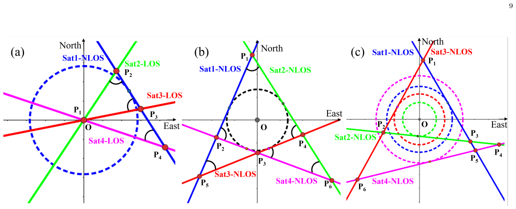
The central object is the satellite circular multipath bias (SCMB) model: the true receiver position is the center of a circle, each satellite's range bias is the radius, and the correlation-peak center line of that satellite's CAF is tangent to the circle. Combined with the linear peak-center-line geometry (slope $-\tan\theta$ and intercept shifted by the projected multipath delay), the model expresses the DPE position error as the chord length $|AB|$ of the bias circle divided by $\sin\Delta\theta$, giving $\delta r = |AB|/\sin\Delta\theta$ through the sine rule. This identity carries the argument from CAF biases to PVT error bounds and to the satellite-selection guidance.
What would settle it
Take two satellites, one with a known NLOS range bias $\delta\rho$ and the other LOS (Case 1), and sweep their azimuth separation $\Delta\theta$ from 90 degrees down to a few degrees. The model predicts $\delta r = \delta\rho / \sin\Delta\theta$, so at $\Delta\theta = 30^\circ$ the error should be $2\delta\rho$ and at $10^\circ$ about $5.76\delta\rho$; a measurement that follows this curve until the finite search grid caps the peak would confirm the geometry, while a plateau far below the prediction would falsify it.
Extended reading notes
Core claim
The paper derives and validates closed-form geometric formulas that trace multipath-induced biases from the cross-ambiguity function to the DPE position, velocity, and time solution. A code-delay bias $\delta\tau$ on channel $m$ becomes a horizontal range bias $\delta\rho = (c/f_c)\,\delta\tau \sec\phi$, and a Doppler bias $\delta f$ becomes a range-rate bias $\delta\dot\rho = (c/f_L)\,\delta f \sec\phi$, where $\phi$ is the satellite elevation. For a pair of satellites with azimuth separation $\Delta\theta$ and range biases $\delta\rho_i$, $\delta\rho_j$, the horizontal position error is $\delta r = \sqrt{(\delta\rho_i)^2+(\delta\rho_j)^2-2\delta\rho_i\delta\rho_j\cos\Delta\theta}\,/\,\sin\Delta\theta$, which the satellite circular multipath bias (SCMB) model reads as a chord length divided by the sine of the included angle. From this, the paper establishes error bounds: with two satellites, the minimum position error equals the larger range bias and the maximum is unbounded as the azimuths approach 0 or $\pi$; with more than two satellites, the minimum is the second-smallest range bias. These claims are confirmed by Monte Carlo simulations and an urban-canyon GPS L5 field test.
Load-bearing premise
The whole derivation assumes the receiver's vertical coordinate and clock bias or drift are known or vary slowly enough to be treated as fixed, so each satellite's correlation peak is a straight line in the horizontal plane and the position solution is just their intersection; if vertical or clock error is not negligible, the closed-form formulas and bounds no longer follow.
Editorial extensions
If this is right
- For two satellites with fixed range biases, the DPE position error can never be smaller than the larger of the two biases, and it grows without bound as their azimuths align.
- In a multi-satellite mix, the best achievable position error is set by the second-smallest satellite range bias, not the smallest.
- With a fixed CAF code-delay or Doppler bias, the resulting position or velocity error grows as $\sec\phi$ with elevation, so high-elevation satellites magnify multipath.
- The SCMB model turns DPE position solving into finding intersections of tangent lines to circles, giving a direct geometric reading of PVT error.
- Satellite selection under multipath should balance high- and low-elevation satellites rather than favor either extreme.
Reading between the lines
- My inference: because the formulas hold for any BPSK code and carrier pair by replacing $f_c$ and $f_L$, the same secant and sine laws should transfer to GPS L1/L2C and to other constellations, though the paper validates only GPS L5.
- My inference: the unbounded maximum error is a mathematical consequence of the infinite-line model; in a real receiver the finite search grid and correlation width cap the error, so the bound should be read as limited only by the search geometry rather than literally infinite.
- My inference: the SCMB construction suggests a multipath analogue of dilution of precision, a scalar built from range biases and azimuth separations that could be computed in real time to down-weight multipath-prone satellites; the paper uses the geometry only for static selection guidance.
- My inference: coupling DPE with an inertial or barometric vertical channel, which pins down z and clock drift, would make the 2D premise realistic in cars and drones; the paper does not test that coupling.
Editorial analysis
A structured set of objections, weighed in public.
Referee Report
Summary. The paper develops a geometric model for how multipath-induced biases in per-satellite cross-ambiguity functions (CAFs) propagate to horizontal position and velocity errors in Direct Position Estimation (DPE). Under the assumption that the vertical coordinate and receiver clock bias/drift are known or slowly varying, each satellite's CAF peak constraint becomes a straight line in the (x, y) plane; the authors derive formulas for the perpendicular range bias (28)-(29), for pairwise PVT errors (32)-(35), and introduce the Satellite Circular Multipath Bias (SCMB) model to bound multipath-induced errors. They then validate the theory with Monte Carlo simulations and a one-epoch urban-canyon data set, and conclude with a satellite-selection rule favoring a balance of high and low elevation angles.
Significance. The paper's main contribution is a set of closed-form, parameter-free geometric mappings from CAF code/Doppler biases to horizontal PVT biases, together with an intuitive SCMB construction and bounds on multipath errors. The algebraic derivation is transparent and internally consistent under the stated 2D, known-z/clock assumptions, and no parameters are fitted to data. If the load-bearing assumptions were quantified and the model were shown to describe the actual DPE cost-function maximizer rather than arbitrary pairwise line intersections, the result would be a useful design rule for DPE in urban multipath. As it stands, however, the Monte Carlo validation largely restates the algebra, and the field evidence is a single selected epoch, so the current support for the central claim is limited.
major comments (5)
- [Section II-B, Eqs. (14)-(15)] The derivation of the straight-line model and all subsequent results (28)-(35) rests on the statement after Eq. (13) that the z-coordinate and receiver clock bias/drift are known or slowly varying. In the standard DPE problem (8), the estimator maximizes over (p, δt, v, δtdot) jointly; each satellite constraint is a hyperplane in R^4. Dropping the z and clock terms turns each constraint into a line in the (x,y) plane, but the horizontal projection of the 4D solution is not generally the intersection of those 2D lines. The paper gives no bound on the neglected vertical/clock errors, although urban-canyon vertical errors can be tens of meters. This is a load-bearing limitation that delimits the regime of validity of the central claim; the authors should either quantify the error introduced by this reduction or extend the geometric construction to the full state space.
- [Section III.C, Figs. 10-11, Tables IV-V] The Monte Carlo validation in Section III.C is circular. It does not simulate DPE at the signal level; it draws random azimuth differences Δθ and evaluates the closed-form formulas (34)-(35), then plots those values as the 'simulated' results. The 'Theoretical' and 'Simulated' entries in Tables IV and V are thus two evaluations of the same algebraic expressions, with the simulated distances read off figures generated from the same tangent-line model. This verifies algebraic consistency but does not test whether the model predicts the behavior of a DPE receiver. An end-to-end simulation with actual CAF generation, summation over satellites, and maximization over the search grid is needed to validate (28)-(35) as a description of DPE.
- [Section III.B and Section II-D, Cases 1-3] The validation of (28)/(29) in Section III.B uses a 'pure NLOS' signal, i.e., only the NLOS path is present, so the CAF peak is trivially at the NLOS delay/Doppler and the measured offset equals the formula by construction. The difficult composite LOS+NLOS case, where the bias of the merged CAF peak depends on relative amplitudes and delays, is never simulated. Relatedly, in Cases 1-3 of Section II-D the DPE estimate is identified with an arbitrary pairwise intersection of center lines, whereas DPE maximizes the summed CAF over all satellites; the selected peak depends on the relative energies of the intersections. The Conclusion itself attributes field discrepancies to 'insufficient consideration of signal energy.' As presented, the bounds are statements about the set of pairwise intersections, not about the actual DPE solution, and this affects the satellite-selection claim.
- [Eq. (39) and Section II-D] The expression for ∂δr/∂Δθ in (39) is dimensionally inconsistent and algebraically wrong as printed: the numerator is written as δρ_i δρ_j cos²Δθ − ((δρ_i)²+(δρ_j)²)cosΔθ + 1, where the final constant term must carry dimensions of squared range. The correct numerator is δρ_i δρ_j(1+cos²Δθ) − ((δρ_i)²+(δρ_j)²)cosΔθ. With the printed version, setting the derivative to zero does not yield the stated critical point Δθ=cos⁻¹(δρ_i/δρ_j); the corrected expression does. Because this derivative underpins the bounds in Section II-D, it should be corrected and the derivation repeated.
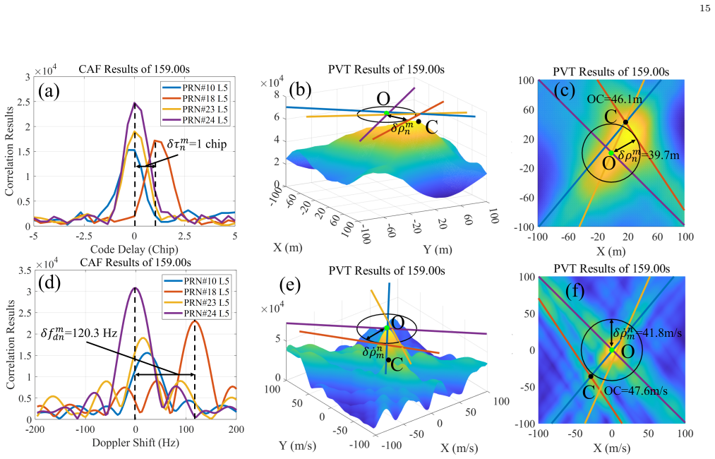
- [Section IV, Table VI] The urban-canyon validation is a single selected epoch (159 s) with no error bars, no repeated trials, and no quantitative comparison across the 200-s dataset. Table VI reports agreement for one set of values, and the Conclusion notes discrepancies between theoretical predictions and field results. This is insufficient support for the Abstract's claim that the model is 'confirmed through ... urban canyon tests.' Reporting statistics over all epochs, or at least a principled selection criterion and a sensitivity analysis, would be needed.
minor comments (5)
- [Throughout] There are several typos and wording issues: 'chanllenging' in the Introduction, 'serve multipath interference' should read 'severe multipath interference,' 'lager bias' should be 'larger bias,' 'correspondance' in the footnote should be 'correspondence,' and 'insufficient' should be 'insufficient.'
- [Section III.A, Table I and text] Table I lists a search grid step of 1 m and 0.1 m/s, while the text in Section III.A states step sizes of 0.25 m and 0.25 m/s; these values should be reconciled.
- [Eq. (40) derivation] In the line following (39), the derivative with respect to the azimuth difference is written as '∂δr/∂δθ = 0'; the notation should be ∂δr/∂Δθ = 0 for consistency.
- [Tables IV and V] The header formatting of Tables IV and V is difficult to parse: the five column labels are merged into one line, and some entries are blank or contain only '/' without explanation. Each pairwise satellite combination and each case should be presented in a clear, unambiguous layout.
- [Section II-D, paragraph after Eq. (40)] The statement that 'δr is a concave function of ∆θ within [0, π]' is questionable, since δr tends to infinity at both endpoints and has an interior minimum; the authors likely mean that it decreases then increases. The wording should be corrected to avoid a false concavity claim.
Circularity Check
Monte Carlo 'verification' regenerates the same SCMB line-intersection formula used to derive Eq. (34), so its agreement is by construction; the algebraic derivation and one-epoch urban test still carry independent content.
-
other
[Section III.C, around Eqs. (34)-(35) and Tables IV-V]
"For illustration, consider PRN #10 and PRN #18. Their azimuth difference, ∆θ, is 106.4°... With the given range and range rate biases, δρmn and δ˙ρmn from Table I, the resulting PVT errors δr and δ˙r should be 84.4 m. To further validate this theory, we performed a Monte Carlo simulation by randomly generating ∆θ uniformly distributed within the range [0, π] and repeated the simulation 10,000 times. The PVT errors obtained from this simulation are illustrated... Additionally, the theoretical values of δr and δ˙r derived from (34) and (35) are provided as a baseline for comparison."
The Monte Carlo 'validation' does not run an independent DPE estimator or add noise. It randomly draws azimuth differences and constructs the same SCMB two-line intersections whose closed-form solution is exactly Eq. (34). The inputs to the simulation are the range/range-rate biases and the sampled ∆θ, which are precisely the inputs of Eq. (34), and the output is the pairwise distance from the intersection to the true position, which is precisely what Eq. (34) computes. Therefore the matching curves in Fig. 11 and the close entries in Tables IV-V are a restatement of the model rather than an independent test. The urban-canyon test in Sec. IV is the only external validation, and the paper itself notes discrepancies there, attributed to insufficient consideration of signal energy.
full rationale
The central derivation is not circular in the strongest sense: Eqs. (28)-(35) are obtained by algebraic manipulation of the straight-line correlation-peak model, with no parameters fitted to data and no target result inserted as an assumption. The straight-line model is inherited from the authors' prior work [13] under the stated assumption that z and receiver clock bias/drift are known or slowly varying; this is a burden on the validity regime rather than a circular definition, since the paper does not quietly redefine DPE as its 2D projection. The SCMB bounds in Section II-D follow by calculus from Eq. (34). The concrete circularity in the evidence chain is the Monte Carlo validation in Section III.C: the simulation samples azimuth differences and constructs intersections under the SCMB model, so comparing those intersections with the closed-form intersection formula (34) is a consistency check, not an empirical confirmation. The field test in Section IV, including the observed 1-chip delay mapping to about 39.7 m range bias and 46.1 m position error versus theoretical values of 39.9 m and 47.2 m, provides an independent albeit single-epoch check and mitigates the circularity. The conclusion's own admission of discrepancies with field results further shows that the formulas are not forced onto the data. Overall, the paper has moderate validation circularity but retains independent algebraic content, so a score of 4 is appropriate.
Assumptions & free parameters
assumptions (6)
- domain assumption The DPE maximum-likelihood problem can be split into independent code-delay and Doppler parts with negligible loss (Section II-A, citing [15]).
- domain assumption The CAF correlation peak center line for a satellite is a straight line in the horizontal position/velocity plane, with slope defined by the satellite azimuth (Section II-B, using results from [13]).
- domain assumption The z-coordinate and receiver clock bias/drift are known or vary slowly, so the estimation reduces to the horizontal plane (Section II-B, paragraph after Eq. (13)).
- domain assumption BPSK correlation is approximated by the ideal triangular function and Doppler by sinc, and multipath is modeled as discrete specular paths (Section II-A, Eqs. (3)-(4)).
- domain assumption The true receiver position is available as the origin for measuring biases (simulation setup and Xsens reference in field test).
- domain assumption Multipath biases δτ and δf can be read directly from the CAF of a pure NLOS signal (Section IV).
Cite this review
Pith. "Pith review of Geometrical portrait of Multipath error propagation in GNSS Direct Position Estimation." pith.science (2026). https://pith.science/paper/WUIBGW2F
@misc{pith2026250718096,
  author       = {Pith},
  title        = {Pith review of: Geometrical portrait of Multipath error propagation in GNSS Direct Position Estimation},
  year         = {2026},
  howpublished = {\url{https://pith.science/paper/WUIBGW2F}},
  note         = {Machine review of arXiv:2507.18096}
}
read the original abstract
Direct Position Estimation (DPE) is a method that directly estimate position, velocity, and time (PVT) information from cross ambiguity function (CAF) of the GNSS signals, significantly enhancing receiver robustness in urban environments. However, there is still a lack of theoretical characterization on multipath errors in the context of DPE theory. Geometric observations highlight the unique characteristics of DPE errors stemming from multipath and thermal noise as estimation bias and variance respectively. Expanding upon the theoretical framework of DPE noise variance through geometric analysis, this paper focuses on a geometric representation of multipath errors by quantifying the deviations in CAF and PVT solutions caused by off-centering bias relative to the azimuth and elevation angles. A satellite circular multipath bias (SCMB) model is introduced, amalgamating CAF and PVT errors from multiple satellite channels. The boundaries for maximum or minimum PVT bias are established through discussions encompassing various multipath conditions. The correctness of the multipath geometrical portrait is confirmed through both Monte Carlo simulations and urban canyon tests. The findings indicate that the maximum PVT bias depends on the largest multipath errors observed across various satellite channels. Additionally, the PVT bias increases with satellite elevation angles, influenced by the CAF multipath bias projection. This serves as a reference for selecting DPE satellites from a geometric standpoint, underscoring the importance of choosing a balanced combination of high and low elevation angles to achieve an optimal satellite geometry configuration.
Figures


Figures from the paper (11 more)




Reference graph
Works this paper leans on
-
[1]
Maximum likelihood estimation of position in GNSS,
P. Closas, C. Fernández-Prades, and J. A. Fernández-Rubio, “Maximum likelihood estimation of position in GNSS,” IEEE Signal Processing Letters, vol. 14, no. 5, pp. 359–362, 2007
work page 2007
-
[2]
P. Closas and A. Gusi-Amigo, “Direct position estimation of GNSS receivers: Analyzing main results, architectures, en- hancements, and challenges,” IEEE Signal Processing Maga- zine, vol. 34, no. 5, pp. 72–84, 2017
work page 2017
-
[3]
Evaluation of GNSS direct position estimation in realistic multipath channels,
P. Closas, C. Fernández-Prades, A. Fernández, M. Wis, G. Vec- chione, F. Zanier, J. Garcia-Molina, and M. Crisci, “Evaluation of GNSS direct position estimation in realistic multipath channels,” in Proceedings of the 28th International Technical Meeting of the Satellite Division of The Institute of Navigation (ION GNSS+ 2015), pp. 3693–3701, 2015
work page 2015
-
[4]
J. Huang, R. Sun, R. Yang, X. Zhan, and W. Chen, “Naviga- tion Domain Multipath Characterization Using GNSS Direct Position Estimation in Urban Canyon Environment,” in Pro- ceedings of the 35th International Technical Meeting of the Satellite Division of The Institute of Navigation (ION GNSS+ 2022), pp. 2606–2617, 2022
work page 2022
-
[5]
Robust Interference Mitigation Techniques for Direct Position Estimation,
H. Li, S. Tang, P. Wu, and P. Closas, “Robust Interference Mitigation Techniques for Direct Position Estimation,” IEEE Transactions on Aerospace and Electronic Systems, vol. 59, no. 6, pp. 8969–8980, 2023
work page 2023
-
[6]
Ng, Improving the robustness of GPS direct position estima- tion
Y. Ng, Improving the robustness of GPS direct position estima- tion. PhD thesis, University of Illinois at Urbana-Champaign, 2016
work page 2016
-
[7]
Im- proved urban navigation with direct positioning and specular matching,
K. Strandjord, P. Axelrad, D. M. Akos, and S. Mohiuddin, “Im- proved urban navigation with direct positioning and specular matching,” in Proceedings of the 2020 International Technical Meeting of The Institute of Navigation, pp. 787–800, 2020
work page 2020
-
[8]
A Pseudo Maximum likelihood approach to position estimation in dynamic mul- tipath environments,
A. Fascista, A. Coluccia, and G. Ricci, “A Pseudo Maximum likelihood approach to position estimation in dynamic mul- tipath environments,” Signal Processing, vol. 181, p. 107907, 2021
work page 2021
Show all 20 references
-
[9]
GNSS direct position estimation-inspired positioning with pseudorange correlogram for urban navigation,
S. Vicenzo, B. Xu, H. Xu, and L.-T. Hsu, “GNSS direct position estimation-inspired positioning with pseudorange correlogram for urban navigation,” GPS Solutions, vol. 28, no. 2, p. 83, 2024
2024
-
[10]
GNSS Multi-Frequency Combined Direct Position Estimation in the Urban Canyon En- vironment,
J. Huang, R. Yang, and X. Zhan, “GNSS Multi-Frequency Combined Direct Position Estimation in the Urban Canyon En- vironment,” in Proceedings of the 36th International Technical Meeting of the Satellite Division of The Institute of Navigation (ION GNSS+ 2023), pp. 2920–2934, 2023. 17
2023
-
[11]
Experimental Investigation of GNSS Direct Position Estimation in Densely Urban Area,
S. Vicenzo, B. Xu, A. Dey, and L.-T. Hsu, “Experimental Investigation of GNSS Direct Position Estimation in Densely Urban Area,” in Proceedings of the 36th International Tech- nical Meeting of the Satellite Division of The Institute of Navigation (ION GNSS+ 2023), pp. 2906–2919, 2023
2023
-
[12]
Maximum-likelihood direct position estimation in dense multipath,
O. Bialer, D. Raphaeli, and A. J. Weiss, “Maximum-likelihood direct position estimation in dense multipath,” IEEE Transac- tions on Vehicular Technology, vol. 62, no. 5, pp. 2069–2079, 2012
2012
-
[13]
Geometric Charac- terization on GNSS Direct Position Estimation in Navigation Domain,
J. Huang, R. Yang, W. Gao, and X. Zhan, “Geometric Charac- terization on GNSS Direct Position Estimation in Navigation Domain,” IEEE Transactions on Aerospace and Electronic Systems, pp. 1–20, 2024
2024
-
[14]
Cross-band correlator and detector design for robust gnss multifrequency combined acquisition,
J. Huang, R. Yang, and X. Zhan, “Cross-band correlator and detector design for robust gnss multifrequency combined acquisition,” IEEE Transactions on Aerospace and Electronic Systems, vol. 59, no. 1, pp. 720–733, 2023
2023
-
[15]
A high performance code and carrier tracking architecture for ground-based mobile GNSS receivers,
L. R. Weill, “A high performance code and carrier tracking architecture for ground-based mobile GNSS receivers,” in Pro- ceedings of the 23rd International Technical Meeting of the Satellite Division of The Institute of Navigation (ION GNSS 2010), pp. 3054–3068, 2010
2010
-
[16]
Design of a parallelized direct position estimation-based GNSS receiver,
M. Peretic and G. X. Gao, “Design of a parallelized direct position estimation-based GNSS receiver,” NA VIGATION: Journal of the Institute of Navigation, vol. 68, no. 1, pp. 21–39, 2021
2021
-
[17]
Global Positioning System: Signals, Measurements, and Performance 1st Edition,
P. Misra and P. Enge, “Global Positioning System: Signals, Measurements, and Performance 1st Edition,”
-
[18]
A novel model for multipath delay estimation and Its application to a modified optimized position estimation algorithm,
N. I. Ziedan, “A novel model for multipath delay estimation and Its application to a modified optimized position estimation algorithm,” in Proceedings of the 35th International Technical Meeting of the Satellite Division of The Institute of Navigation (ION GNSS+ 2022), pp. 213...
2022
-
[19]
Dynamic performance evaluation of various gnss receivers and position- ing modes with only one flight test,
C. Lim, H. Yoon, A. Cho, C.-S. Yoo, and B. Park, “Dynamic performance evaluation of various gnss receivers and position- ing modes with only one flight test,” Electronics, vol. 8, no. 12, p. 1518, 2019
2019
-
[20]
Concurrent validation of the xsens imu system of lower-body kinematics in jump-landing and change-of-direction tasks,
E. M. Nijmeijer, P. Heuvelmans, R. Bolt, A. Gokeler, E. Ot- ten, and A. Benjaminse, “Concurrent validation of the xsens imu system of lower-body kinematics in jump-landing and change-of-direction tasks,” Journal of biomechanics, vol. 154, p. 111637, 2023
2023
Reviewed August 6, 2026 · model on record in the stance chip above.
Discussion (0). Sign in to comment.